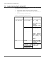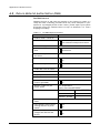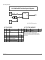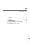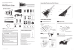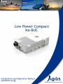
1
Copyright Notice All information contained in this Manual are the property of ST Electronics (Satcom & Sensor Systems) Pte. Ltd. The Manual in whole or in part, may not be duplicated or reproduced without the written permission of ST Electronics (Satcom & Sensor Systems) Pte. Ltd. The Manual is intended to be used as a guide only and may be revised, modified or altered at any time by ST Electronics (Satcom & Sensor Systems) Pte. Ltd. ST Electronics (Satcom & Sensor Systems) Pte. Ltd. shall not be liable to users of the Manual nor to any other person, firm, company or other body for any loss, direct, indirect or consequential, in contract or in tort of for any negligent mis-statement or omission contained herein, by reason of, arising from or in relation to any such user, other person, company or body relying or acting upon or purporting to rely or act upon any matter contained in this Manual. If you have any enquiry or require further technical assistance, please contact our Customer Service Centre at: ST Electronics (Satcom & Sensor Systems) Pte. Ltd. 6 Ang Mo Kio Electronics Park Road Singapore 567711 Hotline: +65 65217959 Fax: +65 65217333 E-mail: [email protected] Website: www.agilissatcom.com © 2013 ST Electronics (Satcom & Sensor Systems) Pte. Ltd. All Rights Reserved. Table of Contents Chapter 1 Product Overview ...............................................................................................1 1.1 About The BUC ........................................................................................1 1.2 BUC Functions .........................................................................................2 1.2.1 BUC Functional Block Diagram ...........................................................3 1.2.2 Transmit Frequency Bands ................................................................3 1.3 BUC Interfaces ........................................................................................4 1.3.1 BUC Front View .............................................................................4 1.3.2 BUC Top View ...............................................................................6 1.3.3 BUC Rear View ..............................................................................6 1.4 Product Models ........................................................................................7 Chapter 2 System Configuration ..........................................................................................9 2.1 System Configuration ................................................................................9 2.1.1 Stand-Alone System Configuration .......................................................9 2.2 System Components ................................................................................ 11 2.2.1 Power Supply Unit ........................................................................ 11 2.2.2 Transient Protection Box ................................................................ 11 Chapter 3 Installation ..................................................................................................... 13 3.1 Unpacking the Box .................................................................................. 13 3.2 Pre-Installation Preparations ..................................................................... 14 3.2.1 Environmental Considerations .......................................................... 14 3.2.2 Tools Required ............................................................................ 14 3.2.3 Site Preparation Checklist .............................................................. 14 3.2.4 Pre-Installation Test ..................................................................... 16 3.3 Installing the BUC & Other Components ........................................................ 17 Chapter 4 BUC Setup and Management ................................................................................ 21 4.1 Monitor & Control................................................................................... 21 4.2 Using the Agilis EMS Software .................................................................... 21 4.2.1 Connecting the PC to the BUC .......................................................... 21 4.2.2 Installing the Agilis EMS Software ...................................................... 22 4.2.3 Launching the Agilis EMS Software .................................................... 23 4.2.4 Main User Interface ...................................................................... 23 4.2.5 Types of Users ............................................................................. 24 4.2.6 Selecting the Device to Manage ........................................................ 24 4.2.7 Modifying Configuration Parameters .................................................. 28 Chapter 5 Maintenance & Troubleshooting ........................................................................... 31 5.1 Preventive Maintenance ........................................................................... 31 5.1.1 Fans Maintenance ......................................................................... 31 5.1.2 Gains Testing .............................................................................. 32 5.1.3 Completing the Maintenance ........................................................... 33 5.2 Understanding Faults in the BUC ................................................................. 34 5.3 Understanding Faults in Remote Management ................................................ 35 Appendix A Customer Service ............................................................................................. 37 A.1 Warranty Information .............................................................................. 37 A.2 Return Material Authorization (RMA) ............................................................ 38 A.3 Additional Technical Support ..................................................................... 40 IM02960202 Rev. B i Appendix B Unit Specifications & Outline ............................................................................... 41 B.1 System Specification Tables ...................................................................... 41 B.2 Power Supply Unit (PSU) .......................................................................... 43 B.3 Unit Outline Drawings .............................................................................. 44 Appendix C Compliance Standards ....................................................................................... 47 Appendix D Document Revision Log ...................................................................................... 49 ii IM02960202 Rev. B List of Figures Figure 1.1 BUC functional block diagram ................................................................................3 Figure 1.2 Front view of the 4W-5W Ka-BUC ............................................................................4 Figure 1.3 Front view of the 8W Ka-BUC .................................................................................4 Figure 1.4 Top view of the 4W-5W Ka-BUC ..............................................................................6 Figure 1.5 Rear view of the 8W Ka-BUC..................................................................................6 Figure 2.1 BUC Stand-Alone System Configuration .....................................................................9 Figure 2.2 Transient Protection Box .................................................................................... 11 Figure 3.1 Connection for uplink test procedure ..................................................................... 16 Figure 3.2 Typical mounting for the Low Power Compact Ka-BUC ................................................ 17 Figure 3.3 Sealing the connectors ....................................................................................... 19 Figure 4.1 Connecting PC to the BUC ................................................................................... 21 Figure 4.2 AgilisEMS.exe icon ............................................................................................ 22 Figure 4.3 Agilis EMS Main User Interface ............................................................................. 23 Figure 4.4 Configuration button ......................................................................................... 28 Figure 4.5 Band Select Configuration................................................................................... 29 Figure B-1 4W – 5W Ka-BUC outline drawing .......................................................................... 44 Figure B-2 8W Ka-BUC outline drawing ................................................................................. 45 IM02960202 Rev. B iii List of Tables Table 1-1 BUC Transmit Frequency Bands for Ka-band ...............................................................3 Table 1-2 Interfaces present on the front panel of the BUC ........................................................4 Table 1-3 M&C connector pin-out configuration .......................................................................5 Table 1-4 Interface present on the rear of the BUC ..................................................................6 Table 1-5 Interface present on the rear of the BUC ..................................................................6 Table 1-6 Product series models .........................................................................................7 Table 2-1 Details of Cables used in Stand-Alone Configuration ................................................... 10 Table 4-1 Cable pin-out configuration ................................................................................. 21 Table 4-2 Types of Users ................................................................................................. 24 Table 4-3 Band Select Frequencies .................................................................................... 28 Table 5-1 AC power tolerance .......................................................................................... 32 Table 5-2 Troubleshooting faults in the BUC ......................................................................... 34 Table 5-3 Troubleshooting errors in remote management using EMS ............................................ 35 Table A-1 Pre-RMA Request Checklist ................................................................................. 38 Table B-1 BUC specification tables ..................................................................................... 41 Table B-2 PSU specification tables ..................................................................................... 43 iv IM02960202 Rev. B Chapter 1 Product Overview Agilis, a global leader in the design, development and manufacturing of quality satellite products for various applications, introduces the Low Power Compact Ka-Band Block-Up Converter (BUC). The Low Power Compact Ka-Band BUC is a highly reliable and cost effective outdoor RF transmitter ideal for mobile and satellite uplink applications. It is suitable for both telephony and high speed data communication. The BUC is easy to install and configure. Small and lightweight, the KaBand BUC is designed to be directly mounted on the feed horn. Its innovative and efficient thermal design makes it one of the smallest, lightest and most reliable in the industry. This user manual provides detailed information to system integrators and end users on how to set-up, operate and maintain the Low Power Compact Ka-Band BUC. 1.1 About The BUC The Compact Ka-BUC can be operated with different modulation formats such as BPSK, QPSK and FM. Due to the stringent performance specifications; it is suitable for the following applications: Single Carrier Per Channel (SCPC) Multi-Carrier Per Channel (MCPC) Demand Assigned Multiple Access (DAMA) Time Division Multiple Access (TDMA) Base band signals are modulated onto L-band frequency and multiplexed with 10 MHz or 50 MHz reference; depending on the model part number, on the IF cable’s centre conductor. It is then up converted and amplified in the Ka-BUC for transmission to the satellite via an antenna dish. The Compact Ka-BUC is designed with low DC power consumption, well suited for applications and systems where power is an important concern. With low pulse mode phase perturbation, it is extremely useful for systems that require burst mode applications. The transmit output waveguide is WR28 grooved. A yellow transparent tape is laminated onto the waveguide and an O-ring is provided to prevent water ingress through the waveguide. Note: Do not remove the yellow transparent tape because it is meant to be permanently laminated at the waveguide transmit output. IM02960202 Rev. B 1 Chapter 1 Product Overview 1.2 BUC Functions The main function of the BUC is to up convert L-band input signals from an indoor modem to a Ka-Band signal for transmission via the antenna. The BUC includes the following function modules: Cooling sub-system The cooling system consists of heat sink and fans and uses forced-air convection cooling. All RF modules are placed on a heat sink for effective heat dissipation. High power devices are cooled by inbuilt fans which operate on DC power generated internally by the power supply unit. Note: Please keep the BUC fans at least 6” away from any obstruction to allow for air circulation through the fans. An over-temperature switch monitors the internal temperature of the unit. When the temperature exceeds acceptable operating limits, the SSPA module is automatically disabled, minimizing damage to the power devices. Solid state power amplifier Each BUC has an internal SSPA module. The BUC feeds up-converted signals into an internal SSPA module to be amplified for transmission to the satellite via the antenna. The SSPA uses high power FETs to generate the required output power. The SSPA operates on DC power internally generated by the internal power supply unit. Monitor and control The M&C module is the central processing hub of the Ka-BUC. It is developed on an embedded microcontroller to perform the required monitoring and control functions. Remote I/O interface and the 48V power supply are provided to the BUC through a single connector. The unit can be connected to a remote PC via serial communication using RS422. Using the M&C module, you can: 2 Control the BUC Configure BUC attenuation Configure BUC for redundancy Enable/Disable RF output power Configure the Band Select Filter Monitor RF (RF output power and temperature) and electrical readings. Check alarm status IM02960202 Rev. B Chapter 1 Product Overview Power supply The Ka-BUC requires a 24V DC (range 18V DC to 50V DC). This DC power is fed into the Ka-BUC via an external power supply. The KaBUC has an in-built Power Supply Unit (PSU) that converts DC power received to the suitable voltages required by the various other modules and fans. The power supply is compact, reliable and has adequate consideration for safety, EMC and EMI. WARNING: The Ka-BUC is automatically powered on when DC power is applied. To avoid damaging the BUC, do not connect the entire setup to the primary AC power source until all connections have been made. 1.2.1 BUC Functional Block Diagram Mixer IF IN RF OUT L-Band and external Ref (10MHz or 50MHz) RMS Power Detector 10MHz or 50MHz Reference DC PLL Synthesizer PSU Tx Power Monitor Monitor & Control M&C Ka-BUC Figure 1.1 BUC functional block diagram Note: The External Reference required by the Ka-BUC depends on the product series model number. The “–N” series Ka-BUC requires an external 50MHz Reference signal multiplexed with the L-Band signal via the IFL line. 1.2.2 Transmit Frequency Bands Table 1-1 BUC Transmit Frequency Bands for Ka-band Frequency Band IF Frequency (MHz) LO Frequency (GHz) Output Frequency (GHz) 4W/8W Ka-BUC 950 1950 27.65 28.60 – 29.60 28.05 29.00 – 30.00 5W Ka-BUC IM02960202 Rev. B 3 Chapter 1 Product Overview 1.3 BUC Interfaces All port connectors on the front, rear and top of the Ka-BUC are sealed to prevent air and moisture from entering the unit and causing damage to the internal components. 1.3.1 BUC Front View Figure 1.2 Front view of the 4W-5W Ka-BUC Figure 1.3 Front view of the 8W Ka-BUC Table 1-2 4 Interfaces present on the front panel of the BUC Port Reference Connector Type Signal Details IF IN 50Ω N-type female. L-band input signal with 10MHz reference or 50MHz reference for the “–N” series models. M&C 12-pin circular type (PT02E-1412P) M&C signal and DC voltage IM02960202 Rev. B Chapter 1 Product Overview The table below describes the pin-out configuration for the M&C connector. Table 1-3 IM02960202 Rev. B M&C connector pin-out configuration Pin # Function Pin A Tx – (RS422) Pin B Tx + (RS422) Pin C Band Select + (RS422) Pin D Band Select – (RS422) Pin E Keyline + (RS422) Pin F Keyline – (RS422) Pin G Rx + (RS422) Pin H Rx – (RS422) Pin J DC + Pin K DC - (Return) Pin L Spare Pin M Spare PA On/Off Control 5 Chapter 1 Product Overview 1.3.2 BUC Top View Figure 1.4 Top view of the 4W-5W Ka-BUC Table 1-4 Interface present on the rear of the BUC Port Reference Connector Type Signal Details RF OUT WR-28 grooved Amplified RF signal 1.3.3 BUC Rear View Figure 1.5 Rear view of the 8W Ka-BUC Table 1-5 6 Interface present on the rear of the BUC Port Reference Connector Type Signal Details RF OUT WR-28 grooved Amplified RF signal IM02960202 Rev. B Chapter 1 Product Overview 1.4 Product Models This manual is suitable for the following Low Power Ka-BUC models: Table 1-6 Product series models Model Type Model Part Number 4W Ka-Band BUC ALB110AEM-4B 4W Ka-Band BUC ALBX10XXX-4X-X 5W Ka-Band BUC ALB110AEM-5B-N 5W Ka-Band BUC ALBX10XXX-5X-X 8W Ka-Band BUC ALB110AEM-8B 8W Ka-Band BUC ALBX10XXX-8X-X Note: External Reference 50MHz for the “-N” series models. IM02960202 Rev. B 7 Chapter 1 Product Overview ---This page is intentionally left blank--- 8 IM02960202 Rev. B Chapter 2 System Configuration This chapter explains, in detail, the system in which the BUC is deployed in and its various components. 2.1 System Configuration The Ka-Band BUC can be deployed in a stand-alone configuration. The stand-alone system configuration setup and its components are discussed below. 2.1.1 Stand-Alone System Configuration 4W – 8W Ka-Band BUC Stand Alone System Configuration Modem L-band, 10MHz IF IN A Ka-BUC RF OUT AC IN TPB PC PSU 1 DC M&C RF OUT To Feed M&C RS422 Figure 2.1 BUC Stand-Alone System Configuration Note: The PSU and TPB are optional items. IM02960202 Rev. B 9 Chapter 2 System Configurations Note: This table lists the typical accessories required for the connection. Please contact Agilis for purchase of any of these accessories if needed. Table 2-1 Details of Cables used in Stand-Alone Configuration Item Agilis Part No. Description Length (m) Quantity 1 2502041458 C/A S/PLUG 14-12S TO M&C DB9 & DC OPEN - 1 A - RF cable (L-Band) To be arranged by the customer - ALB110XXXXX Ka-BUC - 1 - 6401240110 O-RING SILICON 10.5mm X 1.8mm ID - 1 - 6302300310 SCRW HEX SCKT HD SS M3 x 10mm - 4 - APSVAC48-X00 AC-DC Power Unit (optional) Supply - - - 1001520980 AC power cable with transient protection box (optional) 2 - - IM02960202 Installation and Operation Manual - 1 Note: If your purchase includes the PSU, you will be provided with the connecterized Y-cable. Otherwise, the open end cable will be provided instead (P/N: 2502041458). 10 IM02960202 Rev. B Chapter 2 System Configurations 2.2 System Components This section explains the various system components, aside from the BUC unit, that is required to setup the entire system. 2.2.1 Power Supply Unit The Agilis APS series Power Supply Unit (PSU) is a compact and highly reliable standard switching power supply for Agilis BUC products. The PSU receives AC power from a standard AC power source (110V to 230V) and converts it into DC power to be fed into the BUC. Note: The PSU is an optional item. Each PSU is equipped with 2 ports, DC OUT and AC IN. Each port is explained in the table below. Port Reference Connector Type Signal Details DC OUT Amphenol 62IN-12E-12-4S DC voltage to BUC AC IN KPSE02E12-3P For connection to 230VAC or 110VAC using the Agilis’ AC power cable. 2.2.2 Transient Protection Box Transient protection prevents spikes in electrical discharges that may cause damage to the RCU or other connected components. A TPB is connected to both AC input ports of the RCU. AC IN Agilis Transient Protection Box AC OUT M6 Earth Stud Figure 2.2 Transient Protection Box Note: The TPB is an optional item. For the TPB to work effectively, please keep clean outgoing lines away from the incoming or earth leads. Note: Ground the TPB by connecting the M6 Earth Stud to a grounding rod. Note that this is vital to the proper operation of the TPB. IM02960202 Rev. B 11 Chapter 2 System Configurations ---This page is intentionally left blank--- 12 IM02960202 Rev. B Chapter 3 Installation This chapter explains a step-by-step process to safely mount and install your Agilis product. WARNING: Always handle the Ka-BUC with care. Dropping or knocking it may cause damage to the unit. Agilis’ warranty does not extend to defects due to excessive shock or vibration. Do not operate the Ka-BUC without a cable or a RF load connected to the RF OUTPUT waveguide port. The load should be at least double the BUC wattage. 3.1 Unpacking the Box Before unpacking the box, check if it had been damaged or opened. If the shipment may have been tempered with, open the box in front of a representative from the shipping company. Upon opening the box, carefully remove the items in the package and check them against the packing list. If any of the items are damaged or missing, please contact Agilis or your local Agilis representative before proceeding. We recommend that you keep the original packing materials until you have completed the checks and confirmed that the unit is in working order. If you need to repack the product for shipping, please use the original shipping container and packing materials whenever possible. Alternatively, you may also use high quality commercial packing materials to repack the unit. Please seal the container firmly and clearly mark “FRAGILE Electronic Equipment” on the exterior. IM02960202 Rev. B 13 Chapter 3 Installation 3.2 Pre-Installation Preparations 3.2.1 Environmental Considerations The Ka-BUC is a weatherproof, outdoor unit mounted directly onto the orthogonal mount transducer (OMT) of the antenna. This design allows the transmitter (power amplifier) to be installed close to the transmitter antenna. The unit’s aluminium chassis is coated with white, enamelled epoxy for environmental protection. All interface connectors are sealed to prevent air and moisture from entering the unit. Before proceeding with the mounting process, please ensure that the environmental conditions in the area where the BUC is to be mounted is appropriate for its optimal operation. These include: Temperature: -40ºC to +60ºC Relative Humidity: 0 to 100% condensing (rain, snow, ice etc.) Altitude: Up to 10,000 feet (3048m) ASL Solar Radiation: 360 BTU/hr/ft2 (1135 W/m2) Shock and Vibration: As encountered in a typical outdoor earth station environment not in an earthquake zone 3.2.2 Tools Required We highly recommend having the following tools on hand before starting the installation: 1 complete set of socket wrench 1 Philips head screwdriver 1 cutter 1 bag of cable ties (long and Low length) 1 multimeter 3.2.3 Site Preparation Checklist The following table provides a checklist to help you ensure that your site is adequately equipped to perform the installation. Checklist Item 14 Y/N Equipment required for site survey Inclinometer Compass / DataScope 1-meter rectangular bar Scientific calculator 100-meter measuring tape Site location map GPS receiver Road distance wheel Vernier calliper Location markers / flags Is site in the satellite footprint? Yes No IM02960202 Rev. B Chapter 3 Installation Checklist Item Y/N Approximate length of cables between ODU and IDU IF cable routing method Underground Surface Is there a clear path for cables from ODU to IDU? Yes No Proposed mounting location Antenna structure Near the antenna Inside the shelter Other: ________________ Does the mounting location provide the best route for cables from IDU to ODU to antenna? Yes No Is there an unobstructed view from the satellite(s) of interest? Yes No Are there any hazards near the site location that may damage or obstruct the ODU? (old buildings, trees, planned future construction) IM02960202 Rev. B Yes No If yes, please specify: ____________________________ Are there possible RF interference from other nearby telecommunication towers? Yes No Will your installation cause interference to other nearby setup? Yes No Is sufficient power supply available? Yes No Is grounding available? Yes No Is the site prone to the following? Heavy wind Heavy rainfall Ice/snow accumulation Extreme temperatures Sand/Dust storms Others: ______________ 15 Chapter 3 Installation 3.2.4 Pre-Installation Test Performing a pre-installation test prior to the actual field installation helps you to: Confirm that the unit has not been damaged during shipment. Check that the unit is in working order before performing a tiring and costly mounting procedure on your antenna. Note: Ensure that no alarm or fault appears on the Compact Ka-BUC before performing any test. Note: To avoid damaging the Ka-BUC, please connect a 40 dB waveguide attenuator or coupler with a power rating that is at least twice the rated RF output of your BUC. Step 1 Connect the Compact Ka-BUC as shown in the figure below and power up the system. Figure 3.1 Connection for uplink test procedure Note: * represents equipment not provided by Agilis Step 2 Use the L-band satellite modem to input an L-band pure carrier. Turn on the transmit carrier and set the pure carrier feature to ON. Step 3 Adjust the modem’s output power until the IF level input to Compact KaBUC is -50 dBm. 16 IM02960202 Rev. B Chapter 3 Installation Step 4 Measure the RF OUT of the Compact Ka-BUC using a spectrum analyzer at Ka-band. 1. Calculate the total transmit gain based on this formula: Output power – Input power + Amount of attenuation. 2. Compare the result against the specifications (Appendix B Unit Specifications & Outline). If there is no signal, check that the channel setting is correct. Step 5 Replace the spectrum analyzer with a power meter. Measure the rated power of the Compact Ka-BUC by adjusting the input level of the L-band satellite modem. Compare the result against the specifications (Appendix B Unit Specifications & Outline). If there is no signal, check that the channel setting is correct. 3.3 Installing the BUC & Other Components Step 1 All Agilis components in this system are outdoor mounted equipments designed to withstand most weather conditions. Mount the BUC onto the antenna OMT. ANTENNA OMT BUC PLLNB FEED SUPPORT Figure 3.2 Typical mounting for the Low Power Compact Ka-BUC IM02960202 Rev. B 17 Chapter 3 Installation Step 2 Connecting the BUC The following connections need to be performed if you are setting up the BUC in a standalone system configuration. 1. Connect the IF IN port of the BUC to an indoor modem using a standard IF coaxial cable. 2. Connect the M&C port of the BUC to an indoor terminal (such as a PC) for monitoring purposes using the Y cable provided. 3. Connect the third end of the Y cable to a DC supply. Step 3 Grounding the installation This process provides a conductive path for static electrical charges to be discharged safely from the equipment to the ground. This prevents a build up of static charges that may cause the equipment to spark. 1. Locate an appropriate grounding spot. Most soil has sufficient conductivity to allow for an efficient grounding connection. Soils that are mainly rock may need to be treated with additional minerals like rock salt, copper sulphate or magnesium sulphate to increase their conductivity. 2. Drive a 3m lightning rod into the ground about 30cm from the antenna pole. Bolt an aluminium wire, minimum 9mm in diameter, to the ground pole. A tight clamp is used to make contact at the top end. Avoid sharp bends when routing the wire as these may impede current flow. Note: Grounding resistance of the antenna should be no more than 10Ω. WARNING: Please ensure that the wire is tightly connected between the rod and the equipment to prevent sparks. 18 IM02960202 Rev. B Chapter 3 Installation Step 4 Switch on the unit WARNING: Please ensure that the AC power source is off before connecting any devices to AC. FOR STAND ALONE SYSTEMS Connect the PSU to an appropriate AC power source (110V or 230V). Ensure that all connections have been completed before turning on the power supply. The BUC will automatically power on when an appropriate DC current is fed into the unit. Step 5 Sealing the cables To complete the physical installation, all connectors and important joints in the system must be sealed. Note that the sealing must begin from the chassis of the ODUs up to the heatshrink of the cable. All unused connections must be sealed to prevent water ingress. Waveguide joints must be equipped with an appropriate gasket. Please ensure that all connectors are hand tightened before sealing. WAY TO SEAL ALL CONNECTORS WITH SEALANT TAPE WAY TO TIGHTEN CONNECTORS TIGHTEN CONNECTOR DO NOT TURN CABLE CONNECTOR HOUSING ONE HAND TURN HERE HEAT SHRINK CABLE TAPE HERE ONE HAND HOLD HERE TIGHTEN WELL BEFORE TAPING Figure 3.3 Sealing the connectors IM02960202 Rev. B 19 Chapter 3 Installation ---This page is intentionally left blank--- 20 IM02960202 Rev. B Chapter 4 BUC Setup and Management 4.1 Monitor & Control Agilis devices can be monitored and controlled remotely via the Agilis EMS Software. This chapter looks at how you can set up and manage your BUC system using the Agilis EMS Software. 4.2 Using the Agilis EMS Software The Agilis EMS Software is a lightweight network management software that allows the user to monitor and control the Ka-Band BUC remotely through a PC. 4.2.1 Connecting the PC to the BUC +48V DC SUPPLY M&C RS-422 DB-9 ` Figure 4.1 Connecting PC to the BUC Table 4-1 Cable pin-out configuration RS422 cable IM02960202 Rev. B Male Circular Female DB-9 Signal Pin A Pin 1 TxD- Pin B Pin 2 TxD+ Pin G Pin 3 RxD+ Pin H Pin 4 RxD- 21 Chapter 4 BUC Setup and Management 4.2.2 Installing the Agilis EMS Software The Agilis EMS software must be installed into a PC terminal to be used to monitor your Agilis devices. MINIMUM SYSTEM REQUIREMENTS Windows XP / Windows 7 operating system At least 1GB Hard Disk free space 2GB RAM (Recommended) A M&C serial interface SOFTWARE INSTALLATION Note: For detailed information on the Agilis EMS Software, refer to IM02960173 Agilis EMS Software Installation and Operation Manual. Step 1 If an Agilis EMS installation CD is included in your package, please insert the CD into your PC’s disc drive and unzip the setup file. Step 2 Launch the setup file Locate the setup file and double click the file to start the setup. Figure 4.2 AgilisEMS.exe icon Step 3 Follow the step-by-step installation instructions to install the software. Note: You must have administrator permission on your Windows PC to install the software. Step 4 Install the Flash player, Java applet, and the mysql ODBC software inside the 3rd Party Software folder. Note: The 3rd party software must be installed before launching the EMS application; otherwise, the EMS software will not be able to establish communication with the BUC. 22 IM02960202 Rev. B Chapter 4 BUC Setup and Management 4.2.3 Launching the Agilis EMS Software To Launch the Agilis EMS Software, click on Start > All Programs > Agilis EMS, click on the Launch Agilis EMS to start Agilis EMS. Once all the required services are started, an Agilis icon would be displayed in the notification area usually found in the bottom right hand corner. This would indicate that the startup of services has been initiated. An IE (Internet Explorer) window will automatically pop-up upon successful startup. 4.2.4 Main User Interface Figure 4.3 Agilis EMS Main User Interface IM02960202 Rev. B 23 Chapter 4 BUC Setup and Management 4.2.5 Types of Users Table 4-2 Types of Users User Operator (Guest) admin Password NA admin Options Available Analog Charts Device Configuration Analog Charts Device Configuration User Management Note: It is recommended to login as an admin when configuring a device. Configuring a device using an operator account has limitations such as, the need to exit then re-launch the EMS software for the changes to take effect. 4.2.6 Selecting the Device to Manage The Agilis EMS Software can be used to monitor and control a wide range of Agilis products (BUC, MBUC, iBUC, SSPA, LNB, RCU, AUC, SPT and OHT). The Ka-Band BUC is under the BUC (Feedmount-Integrated) category. Before configuring a device, the user must first identify the COM Port assigned to the Agilis device. To identify the COM Port, follow these steps: Step 1 Right click ‘Computer’, and select ‘Properties’. Step 2 Click ‘Device Manager’. Step 3 Double-click ‘Ports (COM & LPT)’ and take note of the Port number assigned to the device. 4.2.6.1 Configuring a standalone BUC 1. 24 Login as an ‘admin’. IM02960202 Rev. B Chapter 4 BUC Setup and Management 2. Click ‘Device Configuration’ under the Administration option in the Menu Bar. 3. Click on the ‘Add device configuration’ option in the Device Configuration window. IM02960202 Rev. B 25 Chapter 4 BUC Setup and Management 4. Under Communication Settings. For Ka-BUC standalone configuration, the Protocol used is ‘Serial’, the COM Port assigned is 7 and the Baud Rate is 38400. Under Device Settings. For the Mode, select ‘Standalone’ For the Setup, select ‘BUC (Feedmount-Integrated)’ The default ‘Acronym’ will be displayed on the Acronyms table. Note: Please use the actual COM Port assigned to your Agilis device under the Device Manager of your PC. The Baud Rate for the Ka-BUC system configurations must be set to 38400. 5. 26 Click ‘Add/Edit’ button. IM02960202 Rev. B Chapter 4 BUC Setup and Management 6. Click ‘Restart Driver’ for the changes to take effect. 7. Click ‘Refresh’ to refresh the display on the Agilis EMS main window. The Tree Menu should display the newly configured device along with the port number. 8. The block diagram of the newly configured device will be displayed on the Agilis EMS main window. IM02960202 Rev. B 27 Chapter 4 BUC Setup and Management 4.2.7 Modifying Configuration Parameters Click on the ‘Configuration’ icon from the control panel to SET device configuration parameters. To change the values of the device, simply click on the boxes where the present values are being displayed. A new window would pop up for the user to enter/select the desired value. Configuration parameters are subjective to equipment type. For the Compact Ka-BUC, the configurable parameters are the RF Output, Attenuation and Band. Figure 4.4 Configuration button The Compact Ka-BUC features a Band Select Filter which allows the user to select either Low Band Input/Output or Wide Band Input/Output through the Agilis EMS Software. Depending on product model and the RF values, the Band Select frequency options are provided in the following table. Table 4-3 Band Select Frequencies Band IF RF LowBand 950 - 1450MHz 28.60 – 29.10GHz 29.00 – 29.50GHz WideBand 950 - 1950MHz 28.60 – 29.60GHz 29.00 – 30.00GHz When using input frequency within 950 – 1450MHz, it is recommended to select Low Band. Selecting Low Band allows the BUC to reject input harmonics, therefore reducing spurious at the output. 28 IM02960202 Rev. B Chapter 4 BUC Setup and Management Figure 4.5 Band Select Configuration IM02960202 Rev. B 29 Chapter 4 BUC Setup and Management ---This page is intentionally left blank--- 30 IM02960202 Rev. B Chapter 5 Maintenance & Troubleshooting This chapter details various system maintenance operations to help ensure that your system works under optimal conditions. WARNING: Disconnect all power sources before performing any system maintenance and repair. 5.1 Preventive Maintenance This section explains the various maintenance checks that should be routinely carried out to ensure that the system is working correctly and in optimal condition. Ideally, you should perform a complete maintenance on the system at least twice a year and record all updates and changes made to each ODU “SETUP RECORD”. Notify all users that may be affected of a system down time of roughly two hours prior to maintenance. WARNING: Disconnect and re-connect cables during maintenance properly to avoid causing any damage to the cables that may result in intermittent problems in the future. Connect the output interface of the equipment to a proper load. 5.1.1 Fans Maintenance The Ka-BUC is equipped with fans at the rear or at the side of the unit. It is essential to ensure that airflow through these fans is not blocked to allow the BUC to operate at the optimal temperature. Hence, we recommend cleaning the fans at least once a year (or more depending on environmental conditions). The cleaning procedure is detailed below: Step 1 Turn off the power supply to the Ka-BUC. Step 2 Using compressed air, blow through the fan assembly to remove any dirt accumulation Step 3 Turn on the power supply to the Ka-BUC. IM02960202 Rev. B 31 Chapter 5 Maintenance & Troubleshooting 5.1.2 Gains Testing The test procedure is as follows: Step 1 Look at the demodulator status (DEMODULATOR LOCK indicator on the modem) and check that is “LOCKED” to the receive signal. Step 2 Check that the transmit and receive configurations on both the modem and the Ka-BUC complies with the SETUP RECORD. If there are any discrepancies, contact the personnel responsible for the previous record for clarifications before proceeding. Step 3 Turn on the pure carrier of the modem and measure the power level using a spectrum analyzer. Step 4 If your modem is connected to an AC power supply, measure the indoor AC power supply to the modem to check that the voltages are within the tolerance limits. You are recommended to use an Automatic Voltage Regulator if your power source falls outside of these limitations. Note: The limit range will differ according to your modem’s AC voltage requirements. Please use the table as a guideline only. Table 5-1 AC power tolerance Tolerance X VAC 50 Hz, where X is the AC requirement of the device Live Neutral X VAC ± 15% Live Earth X VAC ± 15% Neutral Earth < 5 VAC Step 5 Check that all IF and RF cables are labelled. Step 6 Ensure that all cables are in good working condition by performing the following procedure: 1. Remove cables at both ends of the connection before taking measurements. 2. Using a mega ohm meter, measure both ends of the cables. Step 7 Again using a mega ohm meter, measure the ground resistance of the antenna. This value should not be greater than 10Ω 32 IM02960202 Rev. B Chapter 5 Maintenance & Troubleshooting Step 8 Reconnect the transmit cable to the modem and measure the power level of the pure carrier transmitted into the Ka-BUC’s input port. Calculate the IFL loss and check that it is similar to the value recorded in the SETUP RECORD. WARNING: Turn off the Ka-BUC and connect a power attenuator (30dB, >30W) to the RF OUT port of the BUC before step 8 below. Step 9 Turn on the BUC and connect the IF IN cable. Record the RF OUT power level and calculate the uplink gain. Check that the resultant gain complies with both the SETUP RECORD and the gain setting on the BUC. Step 10 Measure the power level and C/N0 of the receive carrier under consideration at the BUC’s RF OUT port. Check the readings against the SETUP RECORD. If there is a significant variation in the two, contact the transmit site for confirmation. Step 11 Measure the level at the modem’s IF input to determine the Rx IFL loss. Match this value against the SETUP RECORD. 5.1.3 Completing the Maintenance Completing each maintenance service requires the following actions: IM02960202 Rev. B Check the sealing on existing connections and re-seal if necessary. Tighten and re-seal all connections and important joints that were disconnected for maintenance. Check and ensure that all waveguide joints are properly equipped with a gasket and sealed. Cover all unused connectors with a cap and seal. Update the SETUP RECORD. 33 Chapter 5 Maintenance & Troubleshooting 5.2 Understanding Faults in the BUC The table below lists the faults that may arise in the BUC. The following information can be found in this table: Fault Indication: How do you tell that a fault has occurred? Possible Causes: What may have caused the fault and how do you check? Solution: How do you resolve the fault? Table 5-2 Troubleshooting faults in the BUC Fault Indication Possible Causes Solution Fans are not working Fans failure Please contact Agilis for further support. No RF output power BUC is overheated RF output is automatically disabled if the BUC is overheated. Allow the unit to cool to a safe operating temperature before enabling RF. RF is disabled (“Off”) Check the BUC settings using the M&C software and enable RF Output (“On”). Internal failure modules One or more of the internal modules, such as the power module, waveguide isolator, BUC driver and internal RF cables, have may have failed. Please contact Agilis for further support. Attenuation setting is too high Check the attenuation setting using the M&C software and adjust accordingly. Gain or power is insufficient to drive the booster modules. BUC is faulty. Please contact Agilis for further support RF output power is low Internal RF cable has high insertion loss 34 IM02960202 Rev. B Chapter 5 Maintenance & Troubleshooting 5.3 Understanding Faults in Remote Management The following table lists the errors that you may face when managing the BUC remotely via the various software methods. Table 5-3 IM02960202 Rev. B Troubleshooting errors in remote management using EMS Fault Indication Possible Causes Solution Agilis EMS is not starting Installation was not done properly Reinstall the application again as stated in this document Windows Firewall Shut down the Windows Firewall service Port 80 is being utilized by another application Shut down the application that is using port 80 Agilis EMS started but the flash images are not shown Flash plug-in may be outdated Reinstall Flash Player preferably from http://get.adobe.com/flashplayer/ Agilis EMS is not logging alarm details /analog parameters MYSQL ODBC connecter is not installed/corrupted Install the application from EMS CD (/3rd Party Software/mysqlconnector-odbc-3.51.14-win32.exe) PC is not showing the COM number M&C cable driver is not installed Install the drivers that came together with the purchased M&C cable (RS232 to USB or RS485 to USB) M&C cable is connected and COM number is seen but still there’s no communication M&C cable could be faulty Replace cable and try again Wrong M&C cable is used Refer to the product manual and ensure that the pin configuration is correct i.e. RS232 or RS485 For standalone mode, the address must be set to ‘A’. Start the application; click the Init Address button to set the device address to ‘A’. ‘Another instance of Agilis EMS is running’ message is displayed when I try to start the application Agilis EMS application is already started Open IE and type http://localhost/agilis-ems in the URL How do I find out the current version number? NA Start the application, click on Help, click on About Us Equipment is not displaying its status properly (e.g. Status toggling online and offline in EV) Equipment Initializing is not done Start the application, click the Init Address button. Equipment Configuration could be wrong Refer to the system manual to make sure the correct configuration is set. RCU is not going online The protocol might be a different version Refer to section 1.4 for the various versions for RCU and how to replace the protocol files if necessary 35 Chapter 5 Maintenance & Troubleshooting 36 Fault Indication Possible Causes Solution System Slowing down Analog and Alarm data is not cleared in the database Purge the historical Analog and Alarm data in the database. IM02960202 Rev. B Appendix A Customer Service Agilis provides a variety of after-sales services. This chapter explains some of the services offered including warranty information, the Return Material Authorization process, parts replacement etc. A.1 Warranty Information If the unit fails due to defects in materials or workmanship, Agilis will, at its sole discretion, repair or replace the defective parts, free of charge, within two years from the date of its shipment from the Agilis production factory. Note that shipping cost to Agilis will not be covered under this warranty guarantee. This warranty will be voided, freeing Agilis from any liability or obligation to the Purchaser with respect to the product in the following situations: IM02960202 Rev. B The product has been damaged during shipment Failure caused by products not supplied by Agilis or its authorized contractors and agents. Failure caused by operation of the product outside of its published electrical and environmental specifications or any causes other than ordinary use. Water ingress due to improper installation. 37 Appendix A Customer Service A.2 Return Material Authorization (RMA) PRE-RMA CHECKLIST Shipping the unit to and from your supplier or the factory for repair is a costly and time consuming procedure that may cause disruption in your system for a prolonged period of time. Hence, please inspect your system thoroughly using the checklist below to help us determine if a return shipping is necessary. Table A-1 Pre-RMA Request Checklist Please check Product model / serial no: When did the unit fail: Initial startup Unit worked normally before failure Initial Fault Symptom: Consistent fault or intermittent Consistent Intermittent Duration of operation before the failure Are fans working normally? Yes No Is the airflow path blocked? Yes No 10 MHz Ref. level at failure IF input level at failure Output power at failure LED status Is the device and properly grounded? setup Yes No Weather conditions just before failure Air Temperature: _________ Heavy rain/snowfall/storms: _________ AC Potential Live Neutral Live Ground Neutral Ground AC-DC converter working status 38 Is the primary power source working and free of power spikes? Yes No Was there any recent power outages that affected the device? Yes No IM02960202 Rev. B Appendix A: Customer Service Please check Are connectors properly sealed and free from debris/water? Yes No Replace the device with a working one (if available) and check if the system works. Works with the new device Does not work with the new device Detail the diagnosis performed that localized the fault to the unit as the point of failure If you need to return the devices or any components to Agilis for repair, please contact Agilis to obtain a Return Material Authorization (RMA) number by filling in our RMA Request form. You can obtain this form via our website at www.agilissatcom.com. Once you receive a RMA number, carefully repack the unit and attach this number to the unit to be shipped to Agilis. Agilis provides repair services for products under or out of warranty. IM02960202 Rev. B 39 Appendix A Customer Service A.3 Additional Technical Support If you require further technical support, please contact Agilis using the contact information below: Address: ST Electronics (Satcom & Sensor Systems) Pte Ltd. 6 Ang Mo Kio Electronics Park Road Singapore 567711 Service Hotline: (+65) 6521 7959 Fax: (+65) 6521 7333 Email: [email protected] You can also visit www.agilissatcom.com for the addresses and contact information of our regional service centres. 40 IM02960202 Rev. B Appendix B Unit Specifications & Outline B.1 System Specification Tables Table B-1 BUC specification tables RF Specifications 4W 5W 8W Transmit Frequency 28.60 29.60 GHz 29.0 – 30.0 GHz 28.60 29.60 GHz IF Frequency Range 950 1950 MHz LO Frequency 27.65 GHz 28.05 GHz 27.65 GHz Output Power@P1db 36dBm 37dBm 39dBm Small Signal Gain 62dB typ 62dB typ 70dB typ Gain Flatness ± 1.5dB 500MHz BW Gain Variation ± 2 dB over the operating temperature range Phase Noise @ offset 1kHz -75 dBc/Hz max 10kHz -81 dBc/Hz max 100kHz -95 dBc/Hz max Input VSWR 1.5:1 Output VSWR 2.0:1 DC Power 4W 5W 8W Primary Power 24VDC (range 18V to 50VDC) Power Consumption 60W (typ) 80W (max) 100W (typ) Interfaces IM02960202 Rev. B IF Input Interface 50Ω N-Type Female Output Interface WR28 grooved 41 Appendix B Unit Specifications & Outline External Reference Requirement Frequency 10MHz 50MHz for the “-N” series models Power External reference phase noise requirement @ frequency offset -5 to +5 dBm -7 to +5 dBm (for 5W Ka-BUC) 1kHz -130 dBc/Hz 10kHz -155 dBc/Hz 100kHz -160 dBc/Hz Environmental Operating Temperature -40ºC to +60ºC Relative Humidity Up to 100% Weather protection sealed to IP65 Mechanical Specifications 42 4W / 5W 8W Dimensions (LxWxH) (mm) 186 x 100 x 51 232 x 152 x 89 Weight 1.6kg 4.2kg Color White Powder Coat IM02960202 Rev. B Appendix B: Unit Specifications & Outline B.2 Power Supply Unit (PSU) Table B-2 PSU specification tables DC Specifications Output Voltage 48V DC typ Output Power 350W AC Mains Input Voltage 110V to 230V AC AC Mains Input Frequency 47 to 63 Hz Protection Overcurrent / Overvoltage Environmental Specifications Operating Temperature -40ºC to +60ºC Relative Humidity Up to 100% Mechanical Specifications IM02960202 Rev. B Dimensions LxWxH 190 x 189 x 107 mm Weight 3kg Color White Powder Coat 43 Appendix B Unit Specifications & Outline B.3 Unit Outline Drawings Figure B-1 4W – 5W Ka-BUC outline drawing 44 IM02960202 Rev. B Appendix B: Unit Specifications & Outline 89 232 152 Figure B-2 8W Ka-BUC outline drawing IM02960202 Rev. B 45 Appendix B Unit Specifications & Outline ---This page is intentionally left blank--- 46 IM02960202 Rev. B Appendix C Compliance Standards IM02960202 Rev. B IEC 609501 2nd Edition International Safety Standard Information Technology Equipment for ETSI EN 301 489-12 Electromagnetic Compatibility and Radio Spectrum Matters (ERM); ElectroMagnetic Compatibility (EMC) Standard for radio equipment and services; Part 12: Specific conditions for Very Small Aperture Terminal, Satellite Interactive Earth Stations operated in the frequency ranges between 4 GHz and 30 GHz in the fixed Satellite Service (FSS) ETSI EN 301 489-1 Electromagnetic Compatibility and Radio Spectrum Matters (ERM); ElectroMagnetic Compatibility Standard for Radio Equipment and Services FCC Part 15 Class B Two levels of radiation and conducted emissions limits for unintentional radiators (FCC Mark) 47 Appendix C Compliance Standard ---This page is intentionally left blank--- 48 IM02960202 Rev. B Appendix D Document Revision Log IM02960202 Rev. B Revision Date Description A January 2013 Initial Release B October 2013 Added information about the 5W Ka-BUC. January 2014 Updated information about Transmit Frequency Bands for 5W Ka-BUC. 49 Appendix D Document Revision Log ---This page is intentionally left blank--- IM02960202 Rev. A 50 System Configuration Diagram 4W – 8W Ka-Band BUC Stand Alone System Configuration Modem L-band, 10MHz IF IN A Ka-BUC RF OUT To Feed RF OUT AC IN PC TPB PSU DC M&C 1 M&C RS422 Note: The PSU and TPB are optional items. LIST OF ACCESSORIES Item No. Agilis Part No. Description C/A S/PLUG 14-12S TO M&C DB9 & DC 1 2502041458 OPEN A RF Cable (L-Band) - 6401240110 O-RING SILICON ID 10.5mm X 1.8mm 6302300310 SCRW HEX SCKT HD SS M3 x 10mm APSVAC48-X00 AC-DC Power Supply Unit 1001520980 AC power cable with TPB IM02960202 IM02960202 Rev. A Installation and Operation Manual LIST OF SYSTEM COMPONENTS Length (m) Quantity 1 Item No. Agilis Part No. ALB110XXXXX To be arranged by the customer 1 Note: These tables list the typical accessories for this setup. Depending on your purchase order, your BUC package may not include certain optional items. Please contact Agilis if you wish to purchase any of the accessories. 2 4 - - 1 Description Ka-Band BUC Quantity 1 51