1
Hochschule Bochum
FB E
Elektrotechnik u. Informatik
Praktikum
DI - Digitaltechnik
Labor für
Automobilelektronik
Betreuung: P. Hunstig (C6-19)
AE-Lab (C6-09)
Versuch 1: Kombinatorische Logik
SS 2015
Hinweise zur Versuchsvorbereitung:
Zu allen Versuchen sind von jedem Teilnehmer die vollständigen Vorübungen in ordentlicher und
nachvollziehbarer Form mitzubringen. Am Versuchstag müssen Sie die wesentlichen Lösungsschritte
flüssig erklären können.
Aufgabenstellung:
Entwickeln Sie eine Logikschaltung zur Ansteuerung einer 7-Segment-Anzeige und zur
Darstellung der Hexadezimal-Ziffern 0 bis F.
Erläuterungen:
Eine 7-Segment-Anzeige besteht aus 7 einzelnen Leuchtbalken (LEDs), mit denen man die 10
Dezimal-Ziffern (0 bis 9) oder auch, wie in der Aufgabenstellung gefordert, die 16 verschiedenen
Ziffern (0 bis F) des Hexadezimalsystems darstellen kann. Jede LED wird über einen eigenen
Signaleingang angesteuert. Je nach Anzeigen-Typ (high- oder low-aktiv) bringt man eine einzelne
LED entweder mit High-Pegel (5 V) oder mit Low-Pegel (0 V) am zugehörigen Signaleingang (a bis g)
zum Leuchten.
In der Aufgabenstellung sollen die Hexadezimal-Ziffern 0 bis F dargestellt werden. An den
Eingängen (B0 – B3) der von Ihnen zu entwickelnden Logikschaltung wird über 4 Schalter der
entsprechende Dualcode der gewünschten Ziffer angelegt. An den Ausgängen a-g der
Logikschaltung müssen dann die richtigen Pegel (Low/High) anstehen, um die passenden Segmente
der Anzeige zum Leuchten zu bringen.
B0
B1
a
a
Logikschaltung
B2
B3
g
Die Schalter (slide switches) am Eingang können zwischen den Stellungen „down“ und „up“
umgeschaltet werden. Stehen alle Schalter auf „down“, soll die Ziffer 0 leuchten; stehen alle
Schalter auf „up“, die Ziffer F.
Hardware:
Evaluationboard:
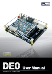
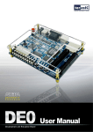
ALTERA DE0
FPGA (Field Programmable Gate Array):
Cyclone III – EP3C16F484C6
Die gesamte Logikschaltung soll in einen programmierbaren Logikbaustein (FPGA) „gebrannt“
werden, der sich zusammen mit den Schaltern und der 7-Segment-Anzeige fertig aufgebaut auf
einem Entwicklungsboard befindet. Im Anhang finden Sie Unterlagen hierzu. Die Logikschaltung
Praktikum DI
DI V1 Aufg SS15.doc
Schugt, Hunstig
werden Sie mit einem komfortablen Softwaretool erstellen und mit den bekannten Logikgattern (AND,
OR, NAND, NOR etc.) aufbauen.
Wichtig zu beachten ist sowohl bei den Schaltern als auch bei den LED-Segmenten der Anzeige, ob
sie low- oder high-aktiv sind.
Welches Signal geben die Schalter in „down“-Position aus, welches in „up“-Position?
Leuchten die LED-Segmente bei High-Pegel oder bei Low-Pegel?
Holen Sie diese Informationen aus den Unterlagen im Anhang und berücksichtigen Sie diese für Ihre
Schaltung.
Software:
Entwicklungstool:
Quartus II (Fa. ALTERA)
Die Entwicklungsumgebung Quartus II von ALTERA dient zur Entwicklung komplexer
Digitalschaltungen für hochintegrierte Logik-ICs (CPLDs, FPGAs). Das Programm stellt hierzu
verschiedene Utilities zur Verfügung wie
Grafik-Editor mit Baustein-Bibliothek
Text-Editor zur Programmierung in AHDL oder VHDL (Hardware Development Language)
Signal-Editor zur Simulation
Timing-Analyse
In diesem Versuch erstellen Sie im Grafik-Editor aus den bekannten Logik-Gattern (AND, OR etc.) die
gesuchte Logikschaltung. Danach testen Sie die Funktionen im Simulator und anschließend
übertragen Sie die Logik in den FPGA-Baustein. Zur Bedienung der Software erhalten Sie am
Versuchstag weitergehende Informationen und Unterlagen.
Unterlagen:
Im Anhang finden Sie eine kurze Übersicht zum Entwicklungsboard DE0 und insbesondere die
notwendigen Informationen zur Benutzung der Schalter (slide switches) und der Siebensegmentanzeigen (7-segment displays).
Praktikum DI
DI V1 Aufg SS15.doc
Schugt, Hunstig
Praktikumsvorbereitung / Vorübung:
Für ein ausreichenes Verständnis des Praktikumsversuchs müssen Sie folgende Grundlagen sicher
beherrschen:
Binär-System, Hexadezimal-System
Funktion der Logik-Verknüpfungen, Kombinatorische Logik, Logik-Gatter (UND, ODER)
Boolsche Gleichungen, Rechenregeln der Schaltalgebra
Wahrheitstabelle
Disjunktive und konjunktive Normalform
Minimierung im KV-Diagramm
Zur Vorbereitung auf den praktischen Teil lösen Sie bitte folgende Aufgaben:
Externe Komponenten:
1. a) Skizzieren Sie, wie ein einfacher Taster (Öffner) in low-aktiver Funktion an einen
Logikeingang anzuschließen ist. Low-aktiv heißt, beim Drücken (Öffnen) des Tasters soll LowPegel am Logikeingang anliegen, beim Loslassen High-Pegel.
Sie werden neben dem Taster noch einen Widerstand verwenden müssen.
Es muss u.a. klar erkennbar sein, wie Taster und Widerstand an der Spannungsversorgung
angeschlossen sind.
b) Skizzieren Sie jetzt den Anschluss desselben Tasters in high-aktiver Funktion.
Hinweis: Beachten Sie, dass ein offener Logikeingang weder high noch low, d.h. nicht definiert ist.
2. a) Skizzieren Sie, wie eine LED low-aktiv an einen Logikausgang anzuschließen ist.
Low-aktiv heißt, bei Low-Pegel am Ausgang soll die LED leuchten, bei High-Pegel nicht.
b) Skizzieren Sie jetzt, wie eine LED high-aktiv an einen Logikausgang anzuschließen ist.
3. Ermitteln Sie anhand der Unterlagen zum Entwicklungsboard DE0, welche Logikpegel die
Schalter in der „down“- bzw. in der „up“-Position ausgeben.
4. Ermitteln Sie ebenso, ob die 7-Segment-Anzeige low-aktiv oder high-aktiv ist. D.h., leuchten
die Anzeigesegmente mit Low- oder High-Pegel?
Siebensegment-Dekoder:
5. Überlegen Sie für jede Hexadezimalziffer, welche Segmente leuchten sollen. Bei den Ziffern
A..F müssen Sie sich jeweils für Groß- oder Kleinschreibung entscheiden, und zwar so, dass alle
16 Hexdezimalziffern eindeutig zu erkennen und zu unterscheiden sind.
6. Stellen Sie eine Wahrheitstabelle auf für den Zusammenhang zwischen den Eingangs-Signalen
(B0-B3, Binär-Code) und den Ausgangs-Signalen (a-g, Segment-Ansteuerungen)
7. a) Stellen Sie für das Segment „e“ die disjunktive Normalform auf.
b) Stellen Sie für das Segment „f“ die konjunktive Normalform auf.
8. Minimieren Sie die Boolschen Gleichungen für die Segmente a und e in disjunktiver Form mit
Hilfe von KV-Diagrammen (1-Felder zusammenfassen), für b und f in konjunktiver Form (0Felder). Die Bearbeitung der übrigen Segmente bleibt Ihnen überlassen (Normal- oder
Minimalform; dijunktiv oder konjunktiv).
9. Konstruieren Sie jetzt für jedes LED-Segment entsprechend den Boolschen Gleichungen die
passende Logikschaltung mit den zugehörigen Gatterelementen (UND, ODER etc.).
Praktikum DI
DI V1 Aufg SS15.doc
Schugt, Hunstig
Wahrheits-Tabelle (truth table)
Dez
Hex
0
0
0
0
0
0
1
I
0
0
0
1
2
2
0
0
1
0
3
3
0
0
1
1
4
4
0
1
0
0
5
5
0
1
0
1
6
6
0
1
1
0
7
7
0
1
1
1
8
8
1
0
0
0
9
9
1
0
0
1
10
A
1
0
1
0
11
B
1
0
1
1
12
C
1
1
0
0
13
D
1
1
0
1
14
E
1
1
1
0
15
F
1
1
1
1
Anzeige B3 B2 B1 B0 a
b
c
d
e
f
g
KV-Tafeln
B3B2
B1 B0
00
00
01
11
10
B3B2
B1 B0
00
01
01
11
11
10
10
B3B2
B1 B0
00
00
01
11
10
B3B2
B1 B0
00
01
01
11
11
10
10
B3B2
B1 B0
00
00
01
11
10
B3B2
B1 B0
00
01
01
11
11
10
10
Praktikum DI
DI V1 Aufg SS15.doc
00
01
11
10
00
01
11
10
00
01
11
10
Schugt, Hunstig
12,7mm LED-Anzeige mit hellgrauer Stirnfläche
HINWEIS: Für jedes Segment ist ein Serienwiderstand zur Begrenzung des Durchlaßstroms
vorzusehen.
Technische Daten
Kingbright-Teile-Nr
Rot (HE)
Superhelles Rot Grün
Einheit
Gemeinsame
Anode
SA05-11EWA SA05-11SRWA
SA05-11GWA
Gemeinsame
Kathode
SC05-11EWA SC05-11SRWA
SC05-11GWA
VF (typ.)
2
1,85
2,2
V
IF (typ.)
20
20
20
mA
IF (max.)
30
30
25
mA
VR (max.)
5
5
5
V
Intensität (min.)
2,2
5,6
2,2
mcd
Intensität (max.)
5,6
21
5,6
mcd
105
mW
105
100
Verlustleistung
Betriebstemperatur: -40°C bis +85°C
Altera DE0 Board
A photograph of the DE0 board depicts the layout of the board and indicates the location of the connectors
and key components.
The DE0 board has many features that allow the user to implement a wide range of designed
circuits, from simple circuits to various multimedia projects.
The following hardware is provided on the DE0 board:
Altera FPGA device Cyclone® III EP3C16F484C6N
Altera Serial Configuration device – EPCS4
USB Blaster (on board) for programming and user API control; both JTAG and Active Serial
(AS) programming modes are supported
8-Mbyte SDRAM
4-Mbyte Flash memory
SD Card socket
3 pushbutton switches
10 toggle switches
10 green user LEDs
50-MHz oscillator for clock sources
VGA DAC (4-bit resistor network) with VGA-out connector
RS-232 transceiver
PS/2 mouse/keyboard connector
Two 40-pin Expansion Headers
Cyclone IIII 3C16 FPGA
15,408 LEs
56 M9K Embedded Memory Blocks
504K total RAM bits
56 embedded multipliers
4 PLLs
346 user I/O pins
FineLine BGA 484-pin package
Built-in USB Blaster circuit
On-board USB Blaster for programming and user API (Application programming interface)
control
Using the Altera EPM240 CPLD
SDRAM
One 8-Mbyte Single Data Rate Synchronous Dynamic RAM memory chip
Supports 16-bits data bus
Flash memory
4-Mbyte NOR Flash memory
Support Byte (8-bits)/Word (16-bits) mode
SD card socket
Provides both SPI and SD 1-bit mod SD Card access
Pushbutton switches
3 pushbutton switches
Normally high; generates one active-low pulse when the switch is pressed
Slide switches
10 Slide switches
A switch causes logic 0 when in the DOWN position and logic 1 when in the UP position
General User Interfaces
10 Green color LEDs (Active high)
4 seven-segment displays (Active low)
16x2 LCD Interface (Not include LCD module)
Clock inputs
50-MHz oscillator
VGA output
Uses a 4-bit resistor-network DAC
With 15-pin high-density D-sub connector
Supports up to 1280x1024 at 60-Hz refresh rate
Serial ports
One RS-232 port (Without DB-9 serial connector)
One PS/2 port (Can be used through a PS/2 Y Cable to allow you to connect a keyboard and
mouse to one port)
Two 40-pin expansion headers
72 Cyclone III I/O pins, as well as 8 power and ground lines, are brought out to two 40-pin
expansion connectors
40-pin header is designed to accept a standard 40-pin ribbon cable used for IDE hard drives
DE0 User Manual
In addition to its use for JTAG and AS programming, the USB Blaster port on the DE0 board can
also be used to control some of the board's features remotely from a host computer. Details that
describe this method of using the USB Blaster port are given in Chapter 3.
4.2
Using the LEDs and Switches
The DE0 board provides three pushbutton switches. The three outputs called BUTTON0, BUTTON
1, and BUTTON2 are connected directly to the Cyclone III FPGA. Each switch provides a high
logic level (3.3 volts) when it is not pressed, and provides a low logic level (0 volts) when
depressed.
There are also 10 slide switches (sliders) on the DE0 board. These switches are not debounced, and
are intended for use as level-sensitive data inputs to a circuit. Each switch is connected directly to a
pin on the Cyclone III FPGA. When a switch is in the DOWN position (closest to the edge of the
board) it provides a low logic level (0 volts) to the FPGA, and when the switch is in the UP position
it provides a high logic level (3.3 volts).
There are 10 user-controllable LEDs on the DE0 board. Each LED is driven directly by a pin on the
Cyclone III FPGA; driving its associated pin to a high logic level turns the LED on, and driving the
pin low turns it off. Figure 4-5 and Figure 4-7show the connections between the push buttons, slide
switches, and Cyclone III FPGA
As indicated in Figure 4-6, each of these switches is debounced using a Schmitt Trigger circuit. The
three outputs called BUTTON0, BUTTON1, and BUTTON2 of the Schmitt Trigger devices are
connected directly to the Cyclone III FPGA (only PCB 10-0100730-A0 version contains the
debounced circuit).
A list of the pin names on the Cyclone III FPGA that are connected to the toggle switches is given
in Table 4.1. Similarly, the pins used to connect to the pushbutton switches and LEDs are displayed
in Table 4.2 and Table 4.3, respectively.
23
DE0 User Manual
Figure 4-5. Connections between the pushbutton and Cyclone III FPGA
Pushbutton depressed
Pushbutton released
Before
Debouncing
Schmitt Trigger
Debounced
Figure 4-6 Switch debouncing
D2
E4
E3
H7
J7
G5
G4
H6
H5
J6
Logic ``1``
SW9
SW8 SW7
SW6 SW5 SW4
SW3 SW2 SW1 SW0
Logic``0``
Figure 4-7 Connections between the toggle switches and Cyclone III FPGA
24
DE0 User Manual
J1
J2
J3
H1
F2
E1
C1
C2
B2
B1
LEDG0
LEDG0
LEDG1
LEDG1
LEDG2
LEDG2
LEDG3
LEDG3
LEDG4
LEDG4
LEDG5
LEDG5
LEDG6
LEDG6
LEDG7
LEDG7
LEDG8
LEDG8
LEDG9
LEDG9
Figure 4-8 Connections between the LEDs and Cyclone III FPGA
Table 4.1. Pin assignments for the slide switches
Signal Name
FPGA Pin No.
Description
SW[0]
PIN_J6
Slide Switch[0]
SW[1]
PIN_H5
Slide Switch[1]
SW[2]
PIN_H6
Slide Switch[2]
SW[3]
PIN_G4
Slide Switch[3]
SW[4]
PIN_G5
Slide Switch[4]
SW[5]
PIN_J7
Slide Switch[5]
SW[6]
PIN_H7
Slide Switch[6]
SW[7]
PIN_E3
Slide Switch[7]
SW[8]
PIN_E4
Slide Switch[8]
SW[9]
PIN_D2
Slide Switch[9]
Table 4.2. Pin assignments for the pushbutton switches
Signal Name
FPGA Pin No.
Description
BUTTON [0]
PIN_ H2
Pushbutton[0]
BUTTON [1]
PIN_ G3
Pushbutton[1]
BUTTON [2]
PIN_ F1
Pushbutton[2]
25
DE0 User Manual
Table 4.3. Pin assignments for the LEDs
4.3
Signal Name
FPGA Pin No.
Description
LEDG[0]
PIN_J1
LED Green[0]
LEDG[1]
PIN_J2
LED Green[1]
LEDG[2]
PIN_J3
LED Green[2]
LEDG[3]
PIN_H1
LED Green[3]
LEDG[4]
PIN_F2
LED Green[4]
LEDG[5]
PIN_E1
LED Green[5]
LEDG[6]
PIN_C1
LED Green[6]
LEDG[7]
PIN_C2
LED Green[7]
LEDG[8]
PIN_B2
LED Green[8]
LEDG[9]
PIN_B1
LED Green[9]
Using the 7-segment Displays
The DE0 board has four 7-segment displays. These displays are arranged into two pairs and a group
of four, with the intent of displaying numbers of various sizes. As indicated in Figure 4-9, the seven
segments are connected to pins on the Cyclone III FPGA. Applying a low logic level to a segment
causes it to light up, and applying a high logic level turns it off.
Each segment in a display is identified by an index from 0 to 6, with the positions given in Figure
4-10. In addition, the decimal point is identified as DP. Table 4.4 shows the connections between the
FPGA pins to the 7-segment displays.
HEX0
HEX0_D0
HEX0_D5
HEX0_D0
HEX0_D1
HEX0_D2
HEX0_D3
HEX0_D1
E11
F11
H12
H13
HEX0_D6
HEX0_D4
HEX0_D4
HEX0_D5
HEX0_D6
HEX0_DP
HEX0_D2
HEX0_D3
HEX0_DP
G12
F12
F13
D13
Figure 4-9 Connections between the 7-segment displays and Cyclone III FPGA
26
DE0 User Manual
0
5
6
4
1
2
DP
3
Figure 4-10 Position and index of each segment in a 7-segment display
Table 4.4. Pin assignments for the 7-segment displays.
Signal Name
FPGA Pin No.
Description
HEX0_D[0]
PIN_E11
Seven Segment Digit 0[0]
HEX0_D[1]
PIN_F11
Seven Segment Digit 0[1]
HEX0_D[2]
PIN_H12
Seven Segment Digit 0[2]
HEX0_D[3]
PIN_H13
Seven Segment Digit 0[3]
HEX0_D[4]
PIN_G12
Seven Segment Digit 0[4]
HEX0_D[5]
PIN_F12
Seven Segment Digit 0[5]
HEX0_D[6]
PIN_F13
Seven Segment Digit 0[6]
HEX0_DP
PIN_D13
Seven Segment Decimal Point 0
HEX1_D[0]
PIN_A13
Seven Segment Digit 1[0]
HEX1_D[1]
PIN_B13
Seven Segment Digit 1[1]
HEX1_D[2]
PIN_C13
Seven Segment Digit 1[2]
HEX1_D[3]
PIN_A14
Seven Segment Digit 1[3]
HEX1_D[4]
PIN_B14
Seven Segment Digit 1[4]
HEX1_D[5]
PIN_E14
Seven Segment Digit 1[5]
HEX1_D[6]
PIN_A15
Seven Segment Digit 1[6]
HEX1_DP
PIN_B15
Seven Segment Decimal Point 1
HEX2_D[0]
PIN_D15
Seven Segment Digit 2[0]
HEX2_D[1]
PIN_A16
Seven Segment Digit 2[1]
HEX2_D[2]
PIN_B16
Seven Segment Digit 2[2]
HEX2_D[3]
PIN_E15
Seven Segment Digit 2[3]
HEX2_D[4]
PIN_A17
Seven Segment Digit 2[4]
HEX2_D[5]
PIN_B17
Seven Segment Digit 2[5]
HEX2_D[6]
PIN_F14
Seven Segment Digit 2[6]
HEX2_DP
PIN_A18
Seven Segment Decimal Point 2
27
DE0 User Manual
4.4
HEX3_D[0]
PIN_B18
Seven Segment Digit 3[0]
HEX3_D[1]
PIN_F15
Seven Segment Digit 3[1]
HEX3_D[2]
PIN_A19
Seven Segment Digit 3[2]
HEX3_D[3]
PIN_B19
Seven Segment Digit 3[3]
HEX3_D[4]
PIN_C19
Seven Segment Digit 3[4]
HEX3_D[5]
PIN_D19
Seven Segment Digit 3[5]
HEX3_D[6]
PIN_G15
Seven Segment Digit 3[6]
HEX3_DP
PIN_G16
Seven Segment Decimal Point 3
Clock Circuitry
The DE0 board includes a 50 MHz clock signals. This clock signal is connected to the FPGA that
are used for clocking the user logic. In addition, all these clock inputs are connected to the phase
lock loops (PLL) clock input pin of the FPGA allowed users can use these clocks as a source clock
for the PLL circuit.
The clock distribution on the DE0 board is shown in Figure 4-11. The associated pin assignments
for clock inputs to FPGA I/O pins are listed in Table 4.5.
Figure 4-11 Block diagram of the clock distribution.
28