1
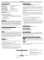
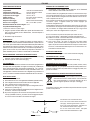
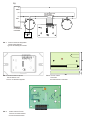
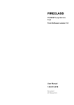
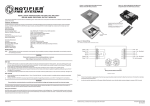
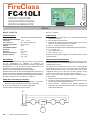
LEAFLET 120-415-931
ISTISBL3FC410LI 2.0 100308
FireClass
FC410LI
MODULO ISOLATORE
LINE ISOLATOR MODULE
KURZSCHLUSSISOLATOR
DEUTSCH
Best.-Nr. 545.800.704
TECHNISCHE DATEN
System-Kompatibilität:
UMGEBUNGSBEDINGUNGEN:
Temperatur:
Rel. Luftfeuchte:
Abmessungen (HxBxT):
Gewicht:
ELEKTRISCHE DATEN:
Ruhestrom:
ausgelöst:
Max. Serienwiderstand:
Drahtdurchmesser:
Best.-Nr. 517.035.007
Adressierbares FC Brandmeldesystem
-25 °C ... +70 °C
max. 95% (ohne Betauung)
60 x 84 x 23 mm
100g
80 µA
max. 3,5 mA
0,25 Ω
min. 0,6 mm2
max. 1,5mm2
BESCHREIBUNG
Der Kurzschlussisolator FC410LI dient zum Isolieren von Kurzschlüssen
auf der adressierbaren FC Meldelinie. Er überwacht den
Leitungszustandder Meldelinie und isoliert bei Kurzschluss den betroffenen
Leitungsabschnitt, d.h. nur der Bereich zwischen zwei FC410LI wird
abgeschaltet, auf dem ein Kurzschluss erkannt wurde.
Damit kann der Rest der Ringleitung normal weiterarbeiten.
Zusätzlich bietet der FC410LI eine Anschlussmöglichkeit für einen Stich, der
ebenfalls auf Kurzschluss überwacht und gegebenenfalls abgeschaltet wird.
Der FC410LI wird aus der Meldelinie gespeist, belegt jedoch keine Adresse.
Eine gelbe LED zeigt an, dass ein Kurzschluss isoliert wird.
EINBAU INS FC470CV ANCILLRY GEHÄUSE
1) Befestigen Sie di FC410LI an der Montageplatte von FC470CV,
benutzen Sie dafür die gelieferte vier Schrauben und Scheiben.
2) Bauen Sie den Deckel auf den doppelten Untergehäuse.
FC470CV Gehäuse-Oberteil ist extra zu bestellen.
a)
FIG. 1
Typische Verdrahtung des FC410LI
VERDRAHTUNG
1 Es müssen keine DIP-Schalter oder Steckbrücken-Einstellungen
vorgenommen werden.
2 Alle Leitungen müssen erdfrei sein.
3 Stellen Sie die korrekte Polung der Verkabelung sicher, bevor Sie den
FC410LI an die Ringleitungsspannung anschließen.
4 Abb. 1a - 1b zeigt eine typische Verdrahtung.
Am 6-poligen Klemmenblock können drei Adernpaare angeschlossen werden :
Ø L+/L-: Linie IN + und Ø S+/S-: Stichabzweig + und Ø R+/R-: Linie OUT + und Der FC410LI ist symmetrisch aufgebaut, d.h. Linie IN und Linie OUT dürfen
vertauscht werden.
ÜBERPRÜFUNG DER VERDRAHTUNG
Herkömmliche Multimeter arbeiten im Widerstandsmessbereich mit sehr
kleinen Spannungen und sind deshalb ungeeignet, eine FC Meldelinie mit
Isolatoren durchzumessen.
Zur Überprüfung der Verdrahtung muss eine auf max. 100 mA begrenzte
Gleichspannung von 24 bis 40 V an einem Ende der Linie eingespeist
werden. Richtige Polarität beachten! Am anderen Ende (oder an jeder
zugänglichen Stelle) der Linie kann dann mit einem Voltmeter geprüft
werden, ob die Verdrahtung bis zu diesem Punkt durchgängig ist.
Falls an diesem Punkt keine Spannung ankommt, kann das folgende
Ursachen haben:
1 Drahtbruch zwischen Einspeisepunkt und Messpunkt.
2 Kurzschluss - bewirkt ein Ansprechen der Kurzschlussisolatoren,wodurch
die Linienspannung nicht weitergeschaltet wird.
3 Falsche Polarität - vertauschte Adern bewirken ebenfalls ein
Ansprechen der Kurzschlussisolatoren, wodurch die Linienspannung
nicht weitergeschaltet wird.
ENGLISH
TECHNICAL SPECIFICATION
VERIFYING LOOP WIRING
System Compatibility:
Use only with FC Fire Alarm Controllers
Environment:
Indoor Application only
o
Operating Temperature:
-25 to +70 C
o
Storage Temperature:
-40 to +80 C
Operating Humidity:
Up to 95% non-condensing
Dimensions (HxWxD):
85 x 60 x 15 mm
Mounting Requirements:
Dual-gang electrical backbox
Recommended Wire Size:
Min. 1.5 mm2 Max. 2.5 mm2
Maximum Wiring Resistance
Monitored Circuit:
10 Ω
Electromagnetic Compatibility
The FC410LI complies with the following:
Ø product family standard EN50130-4 in respect of Conducted Disturbances, Radiated Immunity, Electrostatic Discharge, Fast Transients
and Slow High Energy;
Ø EN61000-6-3 for emissions.
INTRODUCTION
The FC410LI Line Isolator Module is designed to be used on the FC addressable
controller loop circuits. It monitors the line condition and when detecting a short circuit will isolate the affected section whilst allowing the rest of the addressing circuit
to function normally. The purpose of the FC410LI Line Isolator Module is to ensure
that, on a looped addressable system, no short circuit fault can disable more detection devices than would be lost on a conventional non-addressable fire circuit.
INSTALLATION TO FC470CV ANCILLARY COVER
1) Assemble the FC410LI to the FC470CV Double Gang cover, using the
four screw and washers provided.
2) Fit cover onto dual-gang backbox.
CABLING
Cables are to be selected in accordance with the system design document and
the requirements of the applicable standards. One pair of terminals is used to
provide a spur circuit (S+/S-). Two pairs of connection terminals (R+/R- and
L+/L-) are provided on the terminal block. These terminals are used for connecting the module on to the addressable circuit. The maximum section of the cable
that can be connected at any one terminal is 2.5mm2.The section is calculated
based on the characteristics of the cable and the load.
WIRING NOTES
The following notes apply:
1) There are no user-required settings (such as switches or headers) on
the FC410LI.
2) All wiring must conform to the applicable standards.
3) All conductors to be free of earths.
4) Connect loop wiring. For FC410LI typical wiring configurations (see Fig. 1b).
5) Verify the correct polarity of wiring before connecting the FC410LI to the
addressable loop circuit.
6) It is possible to connect a maximum of 32 devices between two loop isolators (FC450IB o FC410LI), note that in the device counting process,
each FC410MIO or each FC410SIO adds a double value.
+ WARNING: DO NOT MEGGER LOOP WIRING WITH LINE
ISOLATOR MODULES CONNECTED.
The Line Isolator Module is not designed to work with line voltages above
the specified maximum 40 Vdc. This means that continuity testing of the
loop wiring with Line Isolator Bases connected must be done using a voltage
between 20-40 Vdc.
The resistance measurement range on conventional voltmeters use low
voltage only, therefore, the following method can be employed to confirm
loop integrity.
A power supply capable of providing 30-40 Vdc with a 300 to 600 mA current
limit is connected to one end of the loop (in correct polarity). A voltmeter is
connected to the other end of the loop or any base along the loop to verify
the wiring up to that point.
If there is no voltage out at any measured point, this may be due to:
1) Loop Open Circuit - wiring incomplete to part of the loop.
2) Incorrect Polarity - FC410LI Line IsolatorModules will appear as a short
circuit if they are wired with incorrect polarity.
3) Loop Short Circuit - If this occurs between two FC410LI Line Isolator
Modules, it will isolate that section of the line, which will then appear as
an open circuit.If this occurs between the supply and the first FC410LI
Line Isolator Modules, the supply output will go low due to the internal
current limit.
ASSOCIATED EQUIPMENT
The module fits onto a standard dual-gang backbox.
ORDERING INFORMATION
FC410LI:
Line Isolator Module
FC470CV: Double-Gang Cover
RECYCLING INFORMATION
Customers are recommended to dispose of their used equipments (panels,
detectors, sirens, and other devices) in an environmentally sound manner.
Potential methods include reuse of parts or whole products and recycling of
products, components, and/or materials.
WASTE ELECTRICAL AND ELECTRONIC EQUIPMENT (WEEE)
DIRECTIVE
In the European Union, this label indicates that this product
should NOT be disposed of with household waste. It should be
deposited at an appropriate facility to enable recovery and recycling.
The manufacturer reserves the right to change the technical specifications
of this product without prior notice.
L+
R+
S+
S-
L-
R-
FC410LI operation
Switches are normally closed.
If a short circuit is detected on the spur, both
switches open.
If a short circuit is detected on the left hand side,
the left hand side switch opens.
If a short circuit is detected on the right hand side,
the right hand side switch opens.
ITALIANO
CARATTERISTICHE TECNICHE
VERIFICA DEI COLLEGAMENTI LOOP
Compatibilità:
usare solo con Centrali serie FC
Caratteristiche ambientali:
Solo per applicazioni interne
o
Temperatura di funzionamento:
da -25 a +70 C
o
Temperatura di stoccaggio:
da -40 a +80 C
Umidità relativa:
fino a 95% (senza condensa)
Dimensioni (HxLxP):
85 x 60 x 15 mm
Requisiti di montaggio:
Scatola americana Dual-Gang
Sezione cavi consigliata:
Min. 1,5 mm2 Max. 2,5 mm2
Resistenza massima del circuito collegato: 10 Ω
Compatibilità Elettromagnetica
L’ FC410LI è conforme a quanto segue:
Ø famiglia di prodotto standard EN50130-4 rispetto alle Perturbazioni Dirette, Immunità Irradiata, Scarica Elettrostatica, Transitorie Rapide e
Alta Energia Lenta;
Ø EN 61000-6-3 per le emissioni.
INTRODUZIONE
Il modulo isolatore FC410LI è progettato per l'utilizzo con centrali serie FC a
loop indirizzabili. Il modulo controlla la condizione della linea e quando rileva un
corto circuito provvede ad isolare la sezione permettendo alla parte restante del
loop indirizzato di continuare a funzionare normalmente. Lo scopo del modulo
isolatore FC410LI è quello di assicurare che, in un sistema a loop indirizzato, un
guasto di corto circuito non possa disattivare più dispositivi di rilevazione di
quanti andrebbero persi in un sistema convenzionale non indirizzabile.
INSTALLAZIONE NEL COPERCHIO ACCESSORI FC470CV
1) Assemblare l'FC410LI con il coperchio per scatole americane Double-Gang
FC470CV usando le quattro viti e le rondelle fornite.
2) Fissare il coperchio sulla scatola dual-gang.
COLLEGAMENTO
I cavi devono essere selezionati in conformità con il documento di progettazione e
nel rispetto delle norme applicabili. Una coppia di morsetti (S+/S-) è utilizzata per
fornire una linea derivata (spur). Due coppie di morsetti (R+/R- , L+/L-) sono presenti sulla morsettiera. Questi morsetti sono usati per connettere il modulo a circuiti indirizzabili. La sezione massima del cavo collegabile ad ogni morsetto è di
2,5 mm2. La sezione và calcolata in base alle caratteristiche del cavo e del carico.
NOTE INSTALLATIVE
Annotazioni da tenere presente:
1)
2)
3)
4)
Sul modulo FC410LI non ci sono regolazioni da effettuare (interruttori o altro).
Tutti i collegamenti devono essere conformi alle norme applicabili.
Tutti i conduttori devono essere senza terra.
Connessioni loop. Per la configurazione tipica di collegamento del modulo FC410LI (vedere Fig. 1b).
5) Verificare la corretta polarità dei collegamenti prima di collegare il modulo FC410LI al circuito a loop indirizzati.
6) Si possono collegare fino ad un massimo di 32 dispositivi tra due isolatori di loop (FC450IB o FC410LI), da notare che nel conteggio dei dispositivi ciascun modulo FC410MIO o FC410SIO vale doppio.
+ ATTENZIONE: NON USARE UN VOLTMETRO ALTA TENSIONE
CON IL MODULO ISOLATORE COLLEGATO.
Il modulo isolatore non è progettato per lavorare con tensione di linea superiore a quella specificata di 40 Vdc. Ciò significa che il test di continuità del
loop con i Moduli Isolatori collegati deve essere effettuato usando una tensione compresa tra 20-40 Vdc.
Alcuni voltmetri convenzionali per la misura della resistenza utilizzano bassa tensione, quindi, il seguente metodo può essere impiegato per
confermare l’integrità del loop.
Un alimentatore capace di fornire una tensione di 30-40 Vdc con una corrente di 300-600 mA và collegato ad una estremità del loop (rispettando le polarità). Un voltmetro và collegato all'altra estremità del loop o lungo la linea
stessa per la verifica del collegamento fino a quel punto.
Se non c'è tensione sui punti misurati questo può essere dovuto a:
1) Loop circuito aperto - collegamenti incompleti sulla parte del loop.
2) Polarità non corretta - Il modulo isolatore FC410LI sembra in corto circuito se non è collegato rispettando le polarità.
3) Loop in corto circuito - Se questo si verifica tra due moduli isolatori
FC410LI, quella sezione di linea si isola apparendo così come circuito
aperto. Se questo avviene tra l'alimentazione ed il primo modulo isolatore FC410LI, l'uscita dell'alimentazione passa ad un valore basso a causa del limite di corrente interno.
ACCESSORI COMPATIBILI
Il modulo può essere alloggiato in una scatola americana dual-gang.
INFORMAZIONI PER L'ORDINE
FC410LI:
Modulo Isolatore
FC470CV: Coperchio per scatola americana Double-Gang
INFORMAZIONI SUL RICICLAGGIO
Si consiglia ai clienti di smaltire i dispositivi usati (centrali, rilevatori, sirene,
accessori elettronici, ecc.) nel rispetto dell'ambiente. Metodi potenziali comprendono il riutilizzo di parti o di prodotti interi e il riciclaggio di prodotti, componenti e/o materiali.
DIRETTIVA RIFIUTI DI APPARECCHIATURE ELETTRICHE ED
ELETTRONICHE (RAEE - WEEE)
Nell'Unione Europea, questa etichetta indica che questo prodotto NON deve essere smaltito insieme ai rifiuti domestici.
Deve essere depositato in un impianto adeguato che sia in
grado di eseguire operazioni di recupero e riciclaggio.
Il costruttore si riserva il diritto di modificare le specifiche tecniche di questo
prodotto senza preavviso.
L+
R+
S+
S-
L-
Schema FC410LI
R-
Gli interruttori sono normalmente chiusi.
Se un corto circuito viene rilevato sulla linea derivata (spur), entrambi gli interruttori si aprono.
Se un corto circuito viene rilevato sulla parte sinistra, l'interruttore laterale sinistro si apre.
Se un corto circuito viene rilevato sulla parte
destra, l'interruttore lateraledestro si apre.
b)
L1
RIGHT
L1
PER LINEA DERIVATA SPUR
FOR SPUR CIRCUIT
ZUR STICHABZWEIGUNG
L1
LEFT
L1
CENTRALE FC
FC CONTROLLER
FC ZENTRALE
LED
HINWEISLEUCHTE
FIG. 1
FC410LI schema di collegamento
FC410LI Wiring Diagram
Typische Verdrahtung des FC410LI
FIG. 2 FC410LI fissata al coperchio
FC410LI fitted to cover
FC410LI ins Gehause eingebäut
FIG. 4
Modulo Isolatore FC410LI
FC410LI Line Isolator Module
FC410LI Kurzschlussisolator
FIG. 3 FC410LI Placca
Facia Plate
Kurzschlussisolator Vorderseite