1
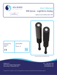
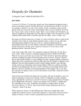
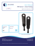
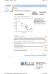
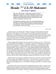
MICRO-GUIDER III
A Telescope to Computer Interface Device You Can Build
by David Lane, Nova Astronomics
updated - June 16, 1997
INTRODUCTION...
The Micro-Guider III (MGIII) is a telescope to computer interface device based on my previous
project, the Micro-Guider I. The original Micro-Guider I is a self-contained device which provides a
telescope with digital setting circles, complete with a database of almost 8,000 celestial objects
including the Messiers and the NGCs. It interacts with the user using an LCD display and a 16 button
keypad. A detailed multi-part article entitled: “MICRO-GUIDER I: A Computerized Setting Circle/
Database Device You Can Build” was published in Observatory Techniques #6 and #7 (Summer and
Fall 1993).
The MGIII is a scaled-down version which reads the telescope’s azimuth and altitude and transmits it
to a suitable computer program upon request. This article will describe the MGIII’s hardware,
software, and construction. It is the author’s intent to provide enough information here to allow the
electronics-inclined telescope maker to build the device themselves. To aid in building the MGIII, the
author has available a supply of blank printed circuit boards and the programmed EPROM chip
needed to complete the device. Some other components may also be available.
DESCRIPTION...
The MGIII is a device which connects to a telescope by using two optical encoders, one attached to
each axis of rotation. The optical encoders translate the rotational movements of the telescope into
electrical signals which are interpreted by the MGIII’s on-board microprocessor.
The current position of the telescope is transmitted to a computer upon request using a standard
RS232 interface. The MGIII is used in conjunction with a suitable computer program which can
translate the telescope’s coordinates into right ascension and declination and act as an aid in locating
objects at the eyepiece (preferably in a graphical way).
The MGIII is designed to be compatible with the author’s shareware Planetarium and Telescope
Control Program for Microsoft® Windows™: The Earth Centered Universe™ (ECU). It is also
compatible with other programs. ECU provides the interface between the telescope, the MGIII, and
the user. I will not discuss the operation of ECU in this article, since the operating procedures are
documented in ECU’s User’s Manual.
As is normal practice with modern digital setting circles, the MGIII will work equally well with
equatorial or alt-azimuth mounted telescopes, since it does not require polar alignment or mount
levelling. Once aligned, ECU provides all the necessary mathematical conversions to use the elapsed
time and the azimuth and altitude (from the MGIII) to calculate the current right ascension and
declination. To initialize the system, ECU asks the user to point the telescope at two stars. Polar
aligned equatorial telescopes need to be aligned on only one star.
HARDWARE...
The MGIII’s hardware consists of one printed circuit board; the same one used in the original MicroGuider I except with fewer components installed. The schematic diagrams of the circuit board are
depicted in Figure 1. The chassis wiring interconnecting the circuit board and the other components is
shown in Figure 2 . This section provides a brief description of how the MGIII works, however it is not
required for the reader to understand how the hardware works to build the device.
The architecture of the MGIII is based on Hitachi’s HD64180 microprocessor. This microprocessor is a
highly integrated version of the older Zilog Z80 microprocessor. Components C2, C3, X1 comprise the
main oscillator which is used to time all functions of the computer. U6 is the EPROM chip (32k bytes)
which is used to store the MGIII’s software. U5 provides 32K bytes of RAM for use by the software.
Not all of this RAM is used; in fact an 8K byte device is sufficient.
The components mentioned in the previous paragraph form a complete fully operational computer.
But a computer by itself, with no input/output, is all but useless. U11 is used to read the outputs from
the encoders. Components U13, and C17-C20 are used to provide the RS232 interface. U12 is used
to regulate positive five volts, which powers all of the circuitry. The minimum operating voltage is
seven volts, but it will operate properly up to at least 15 volts. The current consumption of the
complete MGIII is about 30mA, plus the current used by the encoders (the US Digital encoders
consume about 17mA each). This will provide several hours operation from a standard 9V battery. I
use a 12 volt 6 amp-hour gel-cell battery, which provides power for about a season of observing!
SOFTWARE...
As mentioned above, the MGIII is basically a dedicated computer, thus the software reflects greatly in
its functionality. The software was written in a combination of the ‘C’ programming language and
assembly language. An important part of the software is the encoder routines, written in assembly
language. The optical encoders are read by the software at a rate of 8000 times per second. Each
optical encoder produces two signals which are used to determine the motion (including the direction)
of each telescope shaft. The software interprets these signals to determine the azimuth and altitude of
the telescope.
The remaining part of the program is the interface with the RS232 port. The port is configured at 9600
baud, eight data bits, and one stop bit. This portion is written in ‘C’. There are several commands
supported. The main command ‘Q’, queries the MGIII to transmit the current telescope position. It
responds immediately by sending the azimuth and altitude out the RS232 port to the connected
computer. The format transmitted is shown below:
+00123<tab>+00456<cr>
where:
+00123 is the azimuth
<tab>is an ascii tab character (decimal 9)
+00456 is the altitude
<cr>is an ascii carriage return character (decimal 13)
The resolution of the encoders define the range of output expected in the azimuth and altitude
readings. If 4000 count encoders are used, the range of output is -2000 to +1999 representing the
angles -180 to +180 degrees. Several other commands can be sent to the MGIII for such functions as
setting the encoder resolution, determining the number of encoder errors (if any), etc.
Determining the right ascension and declination of the telescope is quite complex and is calculated by
the PC computer connected to the MGIII. The algorithm which The Earth Centered Universe™ uses
is described in an article published in the Astronomical Computing column of the February 1989 Sky
and Telescope magazine.
CONSTRUCTION...
The construction of the MGIII is quite straight forward. The parts list shown below lists all the materials
necessary to build the MGIII. Most are available from mail order outlets which cater to the hobbyist
(consult the advertisements in a recent electronics hobbiest magazine). If materials sourcing proves
difficult, the author is willing to assist the prospective builder. Many of the actual components listed in
the parts list are only suggestions, and many substitutes are possible. The total cost of the parts is
approximately $200US, including the two optical encoders.
The hardware for mounting the encoders to the telescope axis’ will not be discussed here, since every
telescope will require different mounting hardware.
The circuit board should be populated according to the silkscreen markings on the PCB. Be careful to
note the polarity of the diodes and capacitors and the orientation of the integrated circuits. Be
particularly careful with U2 and its socket. Only install the components identified in the parts list. All of
the other components are not required, since they are used only by the original Micro-Guider I, which
has a real time clock, an LCD, and a keypad.
Components U2, and U6 should be socketed. The remaining IC’s can be socketed, if desired. The
chassis wiring can be performed using ribbon cable, as I have used, following the wiring diagram
shown as Figure 2.
PARTS LIST...
Resistors:
R1.................................................................................................................................. 10K, 0.25W, 5%
R12,R16 ...................................................................................................................... 100K, 0.25W, 5%
Capacitors:
C1,C6 ........................................................................................ 10uF, 25V tantalum (0.2" lead spacing)
C5,C7,C8,C9,C12,C16 .............................................................. 0.1uF, 50V, ceramic (0.2" lead spacing)
C2,C3 ......................................................................................... 22pF, 50V, ceramic (0.2" lead spacing)
C17,C18,C19,C20 ..................................................................... 22uF, 16V, tantalum (0.2" lead spacing)
Semi-Conductors:
X1 ............................................................................................ 12.288MHz crystal (HC-18/U case style)
D1...................................................................................................................................... 1N4001 diode
U1.......................................................................................................................................... 74HC14 IC
U2.....................................................Hitachi HD64180RCP-8X or Zilog Z8018006VSC microprocessor
(Available from the author for $10US)
U3,U4 ......................................................................................................................... 74HC138 decoder
U5............................................................................................. Hitachi HM62256LP-12 32K static RAM
U6............................................................................................................ 27C256 EPROM Programmed
(available from the author for $15US)
U11 ...................................................................................................................................... 74HC373 IC
U12 ......................................................................................................................7805 IC (TO-220 case)
U13 ..................................................................................................................... Maxim MAX232CPE IC
Miscellaneous:
1 ...............................................................................................................................printed circuit board
(Available from the author for $35US)
1 ................................................................................................................. 68 pin PLCC socket (for U2)
1 ....................................................................................................................... 28 pin IC socket (for U6)
2 ......................................................................................................10 contact double row straight male
headers for J4, J6 (0.1" pin spacing)
1 ................................................................................................................................. suitable enclosure
2 ................................................... US Digital Corp. S1-1000 (0.09 degree resolution) optical encoders.
Phone (800) 736-0194 or (206) 696-2468
2 ................................................................................................................................. DB-9P connectors
2 ................................................................................................................................. DB-9S connectors
2 ...................................................................................................... 10 pin IDC ribbon cable connectors
2 ................................................................................................ encoder mountings (telescope specific)
RS232 cable to PC (straight through wiring DB-9S to DB-9P)
Assorted wire and ribbon cable
Assorted hardware
CONCLUSION...
The MGIII provides an inexpensive and easy to build digital setting circle device. The author’s
inexpensive shareware program for Microsoft® Windows™: The Earth Centered Universe (ECU)
provides full support for the MGIII and many other telescopes. ECU, a full featured planetarium and
telescope control program, is available from the author for $50US. The “shareware” version is
available here.
David J. Lane, Nova Astronomics
PO Box 31013 - Halifax, Nova Scotia, Canada, B3K 5T9
Phone: (902) 443-5989 evenings - Fax: (902) 445-5790
Compuserve ID: 71601,247 E-mail: [email protected]
MICRO-GUIDER III - CONTROLLER BOARD
MEMORY
C2
22p
X1
12M288
C3
2
3
4
5
6
7
8
9
10
11
12
13
14
15
16
17
19
20
21
22
23
24
25
26
27
28
29
30
31
32
33
34
22p
U1
+5V
4
RES
74HC14
1N4001
U1
1
+
A0
A1
A2
A3
A4
A5
A6
A7
A8
A9
A10
A11
A12
A13
A14
A15
A16
A17
A18
2
C1
74HC14
10u
SPARE GATES
E0H
U1
13
12
74HC14
U1
11
INT2
100K
10
74HC14
U1
9
+5V
8
RD
WR
ADDRESS DECODING
MREQ
IORQ
A15
A16
A17
1
2
3
MREQ
A18
4
5
6
+5V
RX1
TX1
U3
A0
A1
A2
E1
E2
E3
15
14
13
12
11
10
9
7
00000H
08000H
GND
62256
1
2
3
IORQ
A3
A7
4
5
6
U4
A0
A1
A2
0
1
2
3
4
5
6
7
E1
E2
E3
15
14
13
12
11
10
9
7
U1
EOH
2
6
C18
POWER REGULATOR
U12
VBATT
V+
C1+
C5
+5V
2
+
0u1
C2+
C6 C7 C8 C9 C10 C11
10u
0u1
0u1
0u1
28
+5V
11
12
13
15
16
17
18
19
D0
D1
D2
D3
D4
D5
D6
D7
22
1
20
RD
WR
14
00000H
0u1
+5V
TX0
TX1
J6 5
J6 6
RX0
RX1
J6 7
J6 8
14
7
13
8
1
+
T1OUT
T2OUT
R1IN
R2IN
0u1
T1IN
T2IN
R1OUT
R2OUT
GND
C19
22u
3
D0
D1
D2
D3
D4
D5
D6
D7
2
5
6
9
12
15
16
19
Q0
Q1
Q2
Q3
Q4
Q5
Q6
Q7
OE
E
D0
D1
D2
D3
D4
D5
D6
D7
1
11
3
4
7
8
13
14
17
18
EOH
1 J4
+5V
2 J4
3 J4
CHA-RA
CHB-RA
5 J4
6 J4
CHA-DEC
CHB-DEC
9 J4
GND
74HC373
4
+
MAX232
22u
C2-
POWER SUPPLY DECOUPLING
7805
3
OUT
GND
C20
5
11
10
12
9
22u
TX0
TX1
RX0
RX1
15
FIGURE 1
MARCH 10, 1992
MICRO-GUIDER III
WIRING DIAGRAM
AUGUST 19, 1995
GND
RS232-TX
RS232-RX
RS232 INTERFACE
3
AZIMUTH
ENCODER
S1/S2 SERIES
ALTITUDE
ENCODER
S1/S2 SERIES
N/C
N/C
5
2
J3 (DB-9S)
N/C
J6 9
J6 10
IN
+
V-
1
2
3
4
5
6
7
8
9
10
GND
GND
1
GND
27C256
VCC
C1-
J6 1
J6 2
00
01
02
03
04
05
06
07
OE
VPP
CE
U11
U13
74HC14
VBATT
VBATT
U6
14
08000H
16
C17
+ 22u
R16
100K
RD
WR
+5V
BOH
MICROPROCESSOR
6
22
27
20
A0
A1
A2
A3
A4
A5
A6
A7
A8
A9
A10
A11
A12
A13
A14
RS232 INTERFACE
74HC138
5
D0
D1
D2
D3
D4
D5
D6
D7
VCC
10
9
8
7
6
5
4
3
25
24
21
23
2
26
27
ENCODER INTERFACE
A4
A5
A6
HD64180RCP-8X
74HC14
OE
WR
CE
11
12
13
15
16
17
18
19
A0
A1
A2
A3
A4
A5
A6
A7
A8
A9
A10
A11
A12
A13
A14
74HC138
RX0
TX0
D7
D6
D5
D4
D3
D2
D1
D0
0
1
2
3
4
5
6
7
00
01
02
03
04
05
06
07
+5V
IN4001
J6
GND
10K
R12
68
67
66
65
64
63
62
61
60
59
58
57
56
55
54
53
51
50
49
48
47
46
45
44
43
42
41
40
39
38
37
1
35
36
U5
28
CH. B
+5V
CH. A
D1
CLK
RD
WR
LIR
E
ME
IOE
REF
HALT
TEND1
DREQ1
CKS
RXS
TXS
TEND0
RXA1
TXA1
DREQ0
RXA0
TXA0
DCD0
CTS0
RTS0
D7
D6
D5
D4
D3
D2
D1
D0
GND1
GND3
GND4
VCC
A0
A1
A2
A3
A4
A5
A6
A7
A8
A9
A10
A11
A12
A13
A14
GND
R1
GND2
XTAL
EXTAL
WAIT
BUSACK
BUSREQ
RESET
NMI
INT0
INT1
INT2
ST
A0
A1
A2
A3
A4
A5
A6
A7
A8
A9
A10
A11
A12
A13
A14
A15
A16
A17
A18
VCC
10
9
8
7
6
5
4
3
25
24
21
23
2
26
1
CH. B
+5V
CH. A
3
+5V
U2
A0
A1
A2
A3
A4
A5
A6
A7
A8
A9
A10
A11
A12
A13
A14
DB-9S
MICRO GUIDER III
CONTROLLER BOARD
J4
1
2
3
5
6
9
4
N/C
7
N/C
8
N/C
10
N/C
+5V
CH. A - AZIMUTH
CH. B - AZIMUTH
CH. A - ALTITUDE
CH. B - ALTITUDE
GROUND
1
2
3
5
9
6
8
7
+8-15V
GND
J2 (DB-9P)
FIGURE 2
ALL DIMENSIONS IN INCHES.
S1/S2 OPTICAL SHAFT ENCODERS
DESCRIPTION:
The S1 or S2 series optical shaft encoder is a noncontacting
rotary to digital converter. Useful for position feedback or
manual interface, the encoder converts realtime shaft angle,
speed and direction into TTL-compatible quadrature outputs
with or without index.
The encoder utilizes an unbreakable mylar disk, metal shaft
and bushing, LED light source, monolithic electronics and
operates from a single +5 volt supply.
Available with ball bearings for motion control applications or
torque-loaded to feel like a potentiometer for front-panel
manual interface.
FEATURES:
• Small size
• Low cost
• 2-channel quadrature, TTL square wave outputs
• 3rd channel index option
• Tracks from 0 to 100,000 cycles/sec
• Ball bearing option tracks to 10,000 RPM
• -40 to +100∞C operating temperature
• Single +5v supply
MECHANICAL SPECIFICATIONS:
All Options:
Vibration:
20 g, 5 to 2KHz max.
Acceleration:
250,000 rad/sec2 max.
Sleeve bushing (non-ball bearing)
Shaft Speed:
100 RPM max. continuous
Shaft rotation:
Continuous and reversible
Shaft torque:
0.5±0.2 in. oz.
0.3 in. oz. max. (NT-option)
Shaft loading:
2 lbs. max. dynamic 20 lbs. max. static
Weight:
0.7 oz.
Shaft runout:
.0015 T.I.R. max.
Ball Bearing Option:
Shaft Speed:
10,000 RPM max. continuous
Acceleration:
50K Rad/Sec2
10K Rad/Sec2 (SP-1000 Series)
Shaft torque:
0.05 in. oz. max.
Shaft loading:
1 lb. max.
Bearing Life:
(40/P)3 = Life in millions of revs.
where P=radial load in pounds
Weight:
0.7 oz.
Shaft runout:
.0015 T.I.R. max.
MATERIALS:
Shaft:
Bushing:
Connector:
Brass or Stainless
Brass
Gold plated
MOUNTING:
Hole Diameter:
Panel Thickness:
.380 in.
.125 in. max
ELECTRICAL SPECIFICATIONS:
B leads A in a clockwise shaft rotation, and A leads B in
clockwise shaft rotation viewed from the mounting surface side
of the encoder.
ACCESSORIES:
Cables and Connectors
ORDERING INFORMATION:
U.S. Digital Corp.
3800 N.E. 68th St., Suite A3
Vancouver, WA 98661-1353
800-736-0194
206-696-2468
Fax 206-696-2469
http://www.usdigital.com/
FOR MORE INFORMATION VISIT THE US DIGITAL WEB SITE… http://www.usdigital.com