1
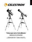
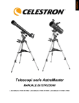
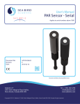
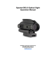
The Micro-Guider 5 User Instructions
A Product of Nova Astronomics
Customer Configuration Data
Serial number:
INTRODUCTION
Firmware version:
The Micro-Guider 5 (MG5) is a telescope to
computer interface device, which connects
between two optical encoders mounted on the axis
of a telescope and a PC’s RS232 port. A suitable
planetarium program, such as the Earth
Centered Universe, can interpret the data
received on the RS232 port to determine the
telescope’s position.
DESCRIPTION
V5.1.0
Manufacture date:
Azimuth resolution:
Altitude resolution:
Power mode:
Power delay:
Encoder Power
jumpers:
DC Power Mode:
4000
4000
On
n/a
By firmware
9-15 volts
The MG5 is a device that connects to a telescope by using two optical encoders (not provided),
one attached to each axis of rotation. The optical encoders translate the rotational movements of
the telescope into electrical signals that are interpreted by the MG5’s microprocessor. The
current position of the telescope is transmitted to a computer upon request using an RS232
interface. The MG5 is used in conjunction with a suitable computer program, which translates
the telescope’s coordinates into right ascension and declination, and act as an aid in locating
objects at the eyepiece (preferably in a graphical way).
The MG5 is designed to be
compatible with the
author’s Planetarium and
Telescope Control Program
for Microsoft Windows:
The Earth Centered
Universe (ECU). It is also
compatible with many other
programs. ECU provides
the interface between the
telescope, the MG5, and the
user. I will not discuss the
operation of ECU in these
instructions, since the
operating procedures are
well-documented in ECU’s
User's Manual. For use with other planetarium programs, consult their user documentation.
As is normal practice with modern digital setting circles, the MG5 will work equally well with
equatorial or alt-azimuth mounted telescopes, since it does not require polar alignment or mount
levelling. Once aligned, the PC planetarium program provides all the necessary mathematical
Micro-Guider 5
1
Rev H – December 2003
conversions to use the elapsed time and the azimuth and altitude (from the MG5) to calculate the
current right ascension and declination. To initialize the system, the user is usually asked to point
the telescope at two stars. Polar aligned equatorial telescopes may only need to be aligned using
one star.
WHAT YOU RECEIVED
The Micro-Guider 5 is shipped with the follow parts:
1.
2.
3.
4.
These instructions
The Micro-Guider 5 (the black box)
1-foot long serial cable assembly
12V DC auto-lighter socket cable
If you are missing any of these parts, contact Nova Astronomics or your purchasing dealer
immediately.
You may also have received a copy of the Earth Centered Universe Pro software and/or
encoder cables.
SPECIFICATIONS
Encoder compatibility
Software compatibility
Encoder sample rate
Power requirements
Power consumption
Power connector
Physical Size (MG5 unit only)
Weight (MG5 unit only)
Colour
Encoder interface connector
Serial interface connector
Serial protocol
Micro-Guider 5
Compatible with +5 volt powered, two channel incremental
encoders. Electrical encoder connector pin-out matches
encoder assemblies sold by Orion Telescopes and
Binoculars and Jim’s Mobile, Inc.
Compatible with Micro-Guider I and III command set.
Emulates the “Q” command of the Lumicon NGC Sky
Vector, Celestron Advanced Astromaster and other similar
devices. Emulates the “Q” and “Z” commands of the Orion
Sky Wizard CTI interface.
16,000/sec in “always-on” encoder power mode, 3000/sec
in “pulsed” encoder power mode.
+8 to +18 volts DC (unregulated) (a 12V auto lighter
socket cable is supplied)
Less than 10mA (excluding encoders) at +9V DC
Standard 2.1mm male coaxial (mate is 5.5mm x 2.1mm
female coaxial)
3.25” x 1.75” x 0.8”
~60 grams
Black
RJ-45
DB-9F (transmits on pin 2, receives on pin 3, with ground
on pin 5)
RS232 (DTE) 9600 baud, 8 data bits, 1 stop bit, no parity
2
Rev H – December 2003
HARDWARE INSTALLATION
The Micro-Guider 5 is very easy to install. It is assumed that your encoders are already installed
on your telescope and ready to plug in to the MG5. Just refer to the photo and follow these steps:
1. Plug the encoder
connector into the
MG5 (it will only
go in one way)
2. Plug the 12V autolighter socket cable
into the MG5.
3. Plug the MG5 with
its attached 1-foot
long serial cable
assembly into your
PC’s 9-pin COM
port.
4. Plug the 12V autolighter socket cable
into a suitable 12V
DC power source.
If you require more that a 1-foot length of cable between your PC and the MG5, you can:
1. use a DB9 extension cable which can either be attached to the included 1-foot long serial
cable assembly or attached directly to the MG5 (after removing the serial cable
assembly).
2. use a four-conductor modular telephone extension cable. Remove one end of the 1-foot
long modular cable and insert the extension cable.
3. remove the 1-foot long section of modular cable and replace it with a longer modular
cable. Note that this cable must be wired in reverse, which is how standard phone cable is
wired to connect between a telephone and a wall outlet.
In all cases above, lengths up to 50 feet are possible.
You can also power the MG5 from a 120VAC (or 240VAC outside of North America) outlet
using a AC adaptor that produces from 9 to 15 volts DC. These adaptors are easily available at
your local Radio Shack or other electronics retailer.
SOFTWARE SETUP
Setup your planetarium software to use the COM port that you connected the MG5 to (usually
COM1) and set the baud rate to 9600. Select the telescope type to one of the following (select the
Micro-Guider 5
3
Rev H – December 2003
first supported model in the list): Micro-Guider 5, Micro-Guider III, Orion Sky Wizard CTI,
Celestron Advanced Astro-Master, Lumicon NGC Sky Vector, Jim’s Mobile NGC-MAX, etc.
If the encoders on your telescope do not match that shown on page 1, you will have to program
the encoder resolution. The Earth Centered Universe Pro software does this automatically
when set the telescope type to Micro-Guider III or Micro-Guider 5. Other planetarium programs
may provide a method of easily doing this – if not, you will have to do this manually using a
terminal program such as “Hyperterminal” (provided with Windows). See the SERIAL
INTERFACE PROTOCOL section below for details.
Due to the mechanical arrangement of your encoders or telescope, you may have to adjust the
number of counts per revolution if any gears or belts are used to attach the encoders to the
telescope. Also, the encoder rotation directions may need to be reversed (which most
planetarium software permits you to do). It you need technical assistance in this area, contact
Nova Astronomics.
ENCODER WIRING
The MG5 is compatible with the
encoders and encoder mounting kits
sold by Jim’s Mobile, Inc.
(www.jimsmobile.com) and by
Orion Telescopes and Binoculars
(www.telescope.com). However if
you decide to wire your own
encoders this section is for you.
The encoders that I recommend
using are available from US Digital
(www.usdigital.com). The models
S1-1000 (4000 count resolution) or
S2-2000 (8000 count resolution) are
good choices.
MG5 RJ45
connector pin
number
1
2
3
4
5
6
7
8
Micro-Guider 5
Function Name (and US Digital
encoder pin number)
US Digital Encoder
(S2 series)
Declination GND (pin 1)
Declination ChA (pin 3)
Declination +5V (pin 4)
Declination ChB (pin 5)
Right Ascension GND (pin 1)
Right Ascension ChA (pin 3)
Right Ascension +5V (pin 4)
Right Ascension ChB (pin 5)
4
Rev H – December 2003
Encoders are connected to the MG5 using an RJ45 connector (this telephone-style connector is
commonly used for Ethernet computer network wiring) according to the diagram above. Readmade encoder cables are available from Nova Astronomics – these are compatible with the
recommended US Digital encoders. If making your own encoder cables, you will need access to
the appropriate RJ45 crimping tool to attach cables to this type of connector.
SERIAL INTERFACE PROTOCOL
This section is for programmers who wish to interface their software to the Micro-Guider 5
(software version 5.1.0) or for those who have to program their encoder resolutions manually.
The MG5 supports many commands issued to it from the PC’s serial (COM) port. Each
command is comprised of ascii characters sent at 9600 baud, 8 data bits, 1 stop bit, and no parity.
Are numbers are in decimal. The list of available commands is:
Command sent to MG5
MG5 returns
Description and Notes
Q
+00123<tab>-00456<cr>
Transmit the encoder values
where:
+00123 is the azimuth (always
6 chars)
-00456 is the altitude (always 6
chars)
<tab> is a tab character (#9)
<cr> is the return character
(#13)
q
Micro-Guider 5
The resolution of the encoders
defines the range of output
expected in the azimuth and
altitude readings. If the encoder
resolutions are <= 32768, the
output is transmitted as a signed
number. For example, if 4000
count encoders are used, the
range of output is -2000 to
+1999. If the encoder
resolutions are > 32768, the
outputs are transmitted as an
unsigned numbers. For
example, if the resolution was
set to 40000, the range of
output would be +00000 to
+39999.
Transmit the number of encoder
errors detected where:
00000<cr>
5
Rev H – December 2003
00000 is a number of errors
(always 5 chars)
<cr> is the return character
(#13)
R01234<tab>04321<cr>
The number of errors is cleared
on power up and increases each
time an encoder error is
detected by the software. There
is often 1 or 2 encoder errors
detected at power up – this is
normal. Other encoder errors
can occur if the encoders are
rotated too fast, if the encoders
themselves are malfunctioning
(eg. too much force on their
shafts), encoder wiring too long
or “noisy.”
Set encoder resolutions (MGIII
mode) where:
R
01234 – azimuth resolution
(always 5 chars)
04321 – altitude resolution
(always 5 chars)
<tab> is the tab character (#9)
<cr> is the return character
(#13)
These values are stored
permanently in non-volatile
memory in the MG5. Encoder
resolutions are accepted up to
65535. Encoder resolutions of
4000 for each axis are
programmed at the factory.
Set encoder resolutions (CTI
mode) where:
Z<tab>+01234<tab>+04321<cr> *
+01234 – azimuth resolution
(always 6 chars)
+04321 – altitude resolution
(always 6 chars)
<tab> is the tab character (#9)
<cr> is the return character
(#13)
Micro-Guider 5
6
Rev H – December 2003
r
01234<tab>04321<cr>
01234 – azimuth resolution
(always 5 chars)
04321 – altitude resolution
(always 5 chars)
<tab> is the tab character (#9)
<cr> is the return character
(#13)
Sets the alignment flag: This is
intended to be used to
determine if the system has
been aligned. This flag is read
with the “a” command and is
cleared on power up or if the
encoder resolutions are
changed.
Returns the status of the
alignment flag set by the “A”
comment. A “Y” is returned if
the flag is set (true) or “N” if
cleared (false).
Set encoder power mode to
100% on. This also causes the
encoders to be read at a rate of
about 16000 Hz. This is the
preferred power mode, unless
very low power consumption
(see “p” command) is desired.
This mode is stored
permanently in non-volatile
memory in the MG5.
Set encoder power mode to
“pulsed” with a delay of “100”
where:
A
a
Y or N
P
P
p100<cr>
p
These values are stored
permanently in non-volatile
memory in the MG5. Encoder
resolutions are accepted up to
65535. Encoder resolutions of
4000 for each axis are
programmed at the factory.
Show encoder resolutions
where:
100 – the relative delay after the
Micro-Guider 5
7
Rev H – December 2003
encoder power is applied before
the encoders are read.
<cr> is the return character
(#13)
V
T
V5.1.0<cr>
Pulsed encoder power reduces
the power consumed by the
encoders (important only if
operating on battery power).
Pulsed power also reduces the
sampling rate of the encoders to
about 3000 Hz, which reduces
the maximum encoder slew
rates considerably. Lower delay
values consume less power;
higher delay values consume
more power. The range of
useful values is 25 to 250. The
recommended value is 100.
Values lower than this can
cause encoder errors. Use the
“T” command below to
experiment before using values
below 100. This value is stored
permanently in non-volatile
memory in the MG5.
Show version number where:
01234,04321,00000<cr>
<cr> is the return character
(#13)
Encoder test mode where:
01234 – azimuth resolution
(always 5 chars)
04321 – altitude resolution
(always 5 chars)
00000 – encoder error count
(always 5 chars)
<cr> is the return character
(#13)
Transmits continuously the
encoder values until a “T” is
received.
Micro-Guider 5
8
Rev H – December 2003
MANUFACTURER CONTACT INFORMATION
David J. Lane, Nova Astronomics
PO Box 31013, Halifax, Nova Scotia, Canada, B3K 5T9
Phone: (902) 499-6196 Fax: (902) 826-7957
E-mail: [email protected]
Website: www.nova-astro.com
DISTRIBUTOR CONTACT INFORMATION
Kendrick Astro Instruments Inc.
2920 Dundas St. West, Toronto, Ontario, Canada M6P 1Y8
Toll Free: (800) 393-5456 Phone: (416) 762-7946
Fax: (416) 762-2765 Email: [email protected]
Website: www.kendrick-ai.com
ONE-YEAR LIMITED WARRANTY
Nova Astronomics warrants that the hardware products it manufactures will be free from defects in materials and
workmanship. All the hardware products that Nova Astronomics sells are tested to ensure that they are functioning
properly before they are shipped. The warranty term is one (1) year beginning on the date that you, the end user,
received the product.
The warranty does not cover damage that is from external causes, including accident, water damage, abuse,
problems with electrical power, servicing not authorized by Nova Astronomics, improper usage, and problems
caused by use of parts and components not supplied by Nova Astronomics.
During the term of this limited warrantee, Nova Astronomics agrees to repair or replace products returned prepaid to
Nova Astronomics. To request warranty service, you must contact Nova Astronomics within the warranty period. If
warranty service is required, Nova Astronomics will issue authorization. You must ship the products back to Nova
Astronomics prepaid with a copy of your dated purchase invoice. Nova Astronomics will ship the repaired or
replacement products to you freight prepaid.
NOVA ASTRONOMICS RESPONSIBILITY FOR DEFECTS IS LIMITED TO REPAIR AND REPLACEMENT
AS SET FORTH IN THIS WARRANTY STATEMENT. NOVA ASTRONOMICS MAKES NO CLAIMS AS TO
THE SUITABILITY FOR ANY SPECIFIC USE AND IN NO EVENT BE LIABLE FOR ANY DAMAGES
WHATSOEVER ARISING OUT OF THE USE OF THIS PRODUCT. NOVA ASTRONOMICS DOES NOT
ACCEPT LIABILITY BEYOND THE REMEDIES SET FORTH IN THIS WARRANTY STATEMENT.
“MICRO-GUIDER”, “THE EARTH CENTERED UNIVERSE”, “ECU”, “MGIII”, AND “MG5” ARE
TRADEMARKS OF NOVA ASTRONOMICS. ALL RIGHTS RESERVED.
“SKY WIZARD” AND “CTI” ARE TRADEMARKS OF ORION TELESCOPES AND BINOCULARS.
“NGC-MAX” IS A TRADEMARK OF JIM’S MOBILE, INC.
“NGC SKY VECTOR” IS A TRADEMARK OF LUMICON INC.
Micro-Guider 5
9
Rev H – December 2003