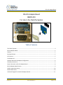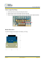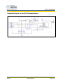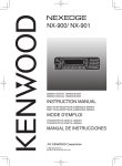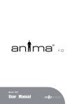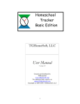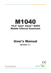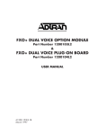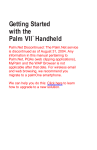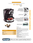
1
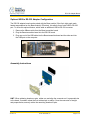
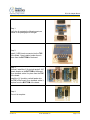
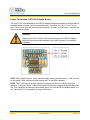
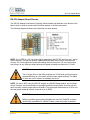
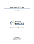
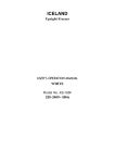
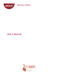
RS-232 Adapter Board User Manual Engineering » Design » Product Blue Wolf, Inc. 9179 W. State Street Garden City, ID 83714 RS-232 Adapter Board Engineering » Design » Product Revision History Version # Release Date Revision/Release Comments 1.0 3/14/2011 Initial draft for release. The information contained in this publication, regarding device applications and/or use, is intended by way of suggestion only and may be superseded by updates or revisions. No liability is assumed by Blue Wolf, Inc. with respect to the accuracy or use of such information or infringement of patents arising from such use or their compliance to any industry standards. The use of Blue Wolf, Inc. products as critical components in any life-saving system is not authorized except with express written approval. Safety glasses should always be worn when assembling this kit and care should be exercised when using any soldering iron equipment or assembly tools. This document is distributed by Blue Wolf, Inc. electronically and may not be printed and distributed without prior written permission. Copyright © Blue Wolf, Inc. 2011. All rights reserved. Version 1.0 © 2011 Blue Wolf, Inc. Page 2 of 11 RS-232 Adapter Board Engineering » Design » Product RS-232 Adapter Board #BWR-003 For Use in the FlashFly System Table of Contents The FlashFly System ...................................................................................................................................... 4 RS-232 Adapter Board................................................................................................................................... 5 Features ........................................................................................................................................................ 5 Key Specifications ......................................................................................................................................... 5 Kit Contents................................................................................................................................................... 5 Tools Required .............................................................................................................................................. 5 Optional USB to RS-232 Adapter Configuration ........................................................................................... 6 Assembly Instructions ................................................................................................................................... 6 Power Connection to RS-232 Adapter Board................................................................................................ 8 RS-232 Adapter Board Pinouts...................................................................................................................... 9 Solder Jumper Non-Stamp .......................................................................................................................... 10 Module Dimensions .................................................................................................................................... 10 Schematic Diagram for the RS-232 Adapter Board..................................................................................... 11 Version 1.0 © 2011 Blue Wolf, Inc. Page 3 of 11 RS-232 Adapter Board Engineering » Design » Product The FlashFly System FlashFly is an innovative system that allows a user to remotely download BASIC Stamp programs to Parallax’s Stamp modules or interpreter chips. FlashFly’s wireless capabilities, in coordination with common Series 1 XBee modules, will allow a user with a BASIC Stamp mobile robot or stationary platform to modify his or her program remotely. Therefore, individuals who have mobile robots, sprinkler systems, weather stations, alarm systems, or any other remote or fixed controller board with a BASIC Stamp core will benefit from the FlashFly system because wirelessly downloading a program change is now achievable and easy. FlashFly eliminates the tedious task of having to connect a robot or a fixed platform to a computer before any programming changes can be made. FlashFly also enriches a user’s learning experience by providing instant feedback data to the DEBUG terminal screen, which allows a user to evaluate his or her program flow and I/O data wirelessly. FlashFly can also be used in conjunction with any other microprocessor platform that needs to transmit data wirelessly. The two main components of the FlashFly system are the Base Module and the Remote Module. These two modules are responsible for communicating back and forth. In the FlashFly system, there are three options for the Remote Module component. Each of these options will allow for wireless downloading of BASIC Stamp programs. 1. The Remote Module can be inserted into a breadboard or user-defined board for direct communication with a BASIC Stamp interpreter chip. 2. The RS-232 serial adapter board can be used in the FlashFly system to connect to a mobile or fixed platform when the user has a serial BASIC Stamp version (a board that uses a DB-9 connecter). 3. The USB Stamp adapter module can be used in the FlashFly system to connect to the Remote Module when the user has a USB-type board with BASIC Stamp. The following list identifies each of the FlashFly system components, their respective product numbers, and their role in FlashFly. The last two boards are interchangeable, depending on the BASIC Stamp version a user has. Base Transmitter Board (BWR-001) – This board connects to the computer. Remote Receiver Board (BWR-002) – This board connects to a mobile or fixed robot. RS-232 Adapter Board (BWR-003) – This board connects to the remote board. USB Stamp Adapter Board (BWR-004) – This board connects to the remote board. Version 1.0 © 2011 Blue Wolf, Inc. Page 4 of 11 RS-232 Adapter Board Engineering » Design » Product RS-232 Adapter Board This RS-232 Adapter board works as an optional attachment for the FlashFly system, and also comes in a partially assembled kit. This cost-effective solution is an easy way to interface the FlashFly system to a serial version Boe-Bot, serial version Board of Education, HomeWork Board, Basic Stamp 2 Carrier Board, or any other serial version using the BASIC Stamp. The basic purpose of the RS-232 adapter board is to convert the I/O signals to and from an RS-232 transmission level. An additional benefit of the RS-232 module, when paired with the Base module, is that it can serve as an extra USB to COMM serial port adapter. NOTE: A USB A to mini B cable is required for use, but it is not supplied. Features Provides an easy interface for communicating with the FlashFly system When used with a Base module, this functions as an extra USB to RS-232 COMM port adapter (TX,RX,DTR) for BASIC Stamps Partially assembled kit for flexible configurations Works with the Remote module or Base module Key Specifications Power requirements: come from a 3 pin 0.100” male header (5Vdc) DB-9 male connector Operating temperature: -40 to +185F (-40 to 85 C) Dimensions: 1.13” wide by 1.30” long (with headers) Kit Contents BWR-003 PCB (1) — SMD components are pre-soldered DB-9 male straight connector (1) — Solder to top of board 8-pin right angle 0.100” female header (1) 3 pin 0.100” vertical header for easy power input (1) Tools Required Version 1.0 Soldering iron (always wear safety glasses when soldering) Solder (some soldering experience required) Flux © 2011 Blue Wolf, Inc. Page 5 of 11 RS-232 Adapter Board Engineering » Design » Product Optional USB to RS-232 Adapter Configuration The RS-232 adapter board can be paired with the Base module (if the 8-pin right angle male header was soldered on the Base module). Effectively, this allows for an extra USB to RS-232 port. To utilize this optional feature, which adds an additional USB to RS-232 converter: 1. Remove the XBee module from the Base transmitter board. 2. Plug the Base transmitter board into the RS-232 board. 3. Plug one end of the USB cable into the Base transmitter board and the other end into the USB port on the computer. Assembly Instructions HINT: When soldering headers or pins, solder one and align the connector so it is perpendicular to the board. If needed, reheat the first soldered pin to realign. Once the connector is straight and perpendicular, securely solder the remaining headers or pins. Version 1.0 © 2011 Blue Wolf, Inc. Page 6 of 11 RS-232 Adapter Board Engineering » Design » Product Step 1: Verify the kit contains the following parts, as shown in the photograph to the right. Step 2: Install (1) DB-9 male connector into the TOP of the board. Once installed, solder them in place from the BOTTOM of the board. Step 3: Optional, install the (1) 8-pin right angle 0.100” female header on the BOTTOM of the board. Once installed, solder it in place from the TOP of the board. Install the (1) 3-position vertical header into the TOP of the board. Once installed, solder it in place from the BOTTOM of the board. Step 4: The unit is complete. Version 1.0 © 2011 Blue Wolf, Inc. Page 7 of 11 RS-232 Adapter Board Engineering » Design » Product Power Connection to RS-232 Adapter Board The 3-pin 0.100” vertical header on the RS-232 adapter board was designed to accommodate a standard female to female 3-pin servo extender cable. The center pin is for +5.0 to +5.5 Vdc input. The outer two pins are both connected to ground. This way, an inadvertent connection will not reverse power polarity. CAUTION Applying more than +5.5Vdc to the power connector on the RS-232 adapter board can cause permanent damage to the FlashFly system, thus making it inoperable. NOTE: With a singular jumper, a user can also simply connect the center pin to +5 Vdc (or Vdd) on the system, since the ground comes through pin 5 of the DB-9 connector. NOTE: The 5.0 Vdc source must be capable of supplying a minimum of 100 mA for proper operation. If using the Series 1 XBee Pro modules, this must be increased to approximately 200 mA. This is because the Remote module board gets 5 Vdc from the RS-232 adapter board. It, in turn, has its own 3.3 Vdc regulator for proper functionality. Version 1.0 © 2011 Blue Wolf, Inc. Page 8 of 11 RS-232 Adapter Board Engineering » Design » Product RS-232 Adapter Board Pinouts The RS-232 adapter board has an 8-position female header that attaches to the bottom of the board, which is used to connect either the Base module or the Remote module. The following diagram illustrates the information for these pinouts. NOTE: Pin 6 (RSP) is a 3.3 Vdc output signal representing the RS-232 level from pin 7 on the DB-9 connector. This can be used for experimental purposes when using a microcontroller circuitry. Pin 6 on the Remote module has nothing else connected to it, so one could jumper from that pin to any XBee pin safely because this signal is already conditioned to 3.3 volts. CAUTION The I/O signal lines on the XBee modules are 3.3Vdc level and should not be connected direclty to a 5V system without proper signal buffering. The XBee I/O lines are not 5V tolerant, so damage may occur. NOTE: If a user is NOT using the RS-232 adapter on a BASIC Stamp product, but is instead using it on one’s own microcontroller or a straight wireless communication, then the user will have to modify a solder jumper pad on the board. The solder pad disconnects pin 2 RXA, and the new jumper soldered in place connects to pin 4 (RXB). WARNING Modifying a solder jumper pad will disable the use of the FlashFly in-system downloading capabilities for a BASIC Stamp unless the jumper is replaced. Version 1.0 © 2011 Blue Wolf, Inc. Page 9 of 11 RS-232 Adapter Board Engineering » Design » Product Solder Jumper Non-Stamp 1. Cut the trace from the center pad to the pad on the left. 2. Solder a jumper from the center pad to the pad on the right. 3. Solder a jumper from the center pad to the pad on the left (to restore original operation). Module Dimensions The RS-232 adapter board measures 1.25” wide by 1.30” long. Version 1.0 © 2011 Blue Wolf, Inc. Page 10 of 11 RS-232 Adapter Board Engineering » Design » Product Schematic Diagram for the RS-232 Adapter Board Version 1.0 © 2011 Blue Wolf, Inc. Page 11 of 11 Mouser Electronics Authorized Distributor Click to View Pricing, Inventory, Delivery & Lifecycle Information: Parallax: 28182