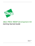
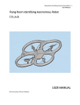
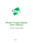
1
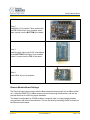
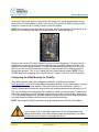
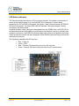
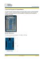
Remote Module Board User Manual Engineering » Design » Product Blue Wolf, Inc. 9179 W. State Street Garden City, ID 83714 Remote Module Board Engineering » Design » Product Revision History Version # Release Date Revision/Release Comments 1.0 3/14/2011 Initial draft for release. The information contained in this publication, regarding device applications and/or use, is intended by way of suggestion only and may be superseded by updates or revisions. No liability is assumed by Blue Wolf, Inc. with respect to the accuracy or use of such information or infringement of patents arising from such use or their compliance to any industry standards. The use of Blue Wolf, Inc. products as critical components in any life-saving system is not authorized except with express written approval. Safety glasses should always be worn when assembling this kit and care should be exercised when using any soldering iron equipment or assembly tools. This document is distributed by Blue Wolf, Inc. electronically and may not be printed and distributed without prior written permission. Copyright © Blue Wolf, Inc. 2011. All rights reserved. Version 1.0 © 2011 Blue Wolf, Inc. Page 2 of 12 Remote Module Board Engineering » Design » Product Remote Module Board # BWR-002 For Use in the FlashFly System Table of Contents The FlashFly System ...................................................................................................................................... 4 Remote Module Board.................................................................................................................................. 5 Features ........................................................................................................................................................ 5 Key Specifications ......................................................................................................................................... 5 Kit Contents................................................................................................................................................... 5 Tools Required .............................................................................................................................................. 5 Application Ideas........................................................................................................................................... 6 Assembly Instructions ................................................................................................................................... 6 Remote Module Board Settings .................................................................................................................... 7 Configuring the XBee Modules for FlashFly .................................................................................................. 8 LED Status Indicators .................................................................................................................................... 9 Connection Diagrams for Remote Module ................................................................................................. 10 Module Dimensions .................................................................................................................................... 10 Special Usage Notes .................................................................................................................................... 11 Version 1.0 © 2011 Blue Wolf, Inc. Page 3 of 12 Remote Module Board Engineering » Design » Product The FlashFly System FlashFly is an innovative system that allows a user to remotely download BASIC Stamp programs to Parallax’s Stamp modules or interpreter chips. FlashFly’s wireless capabilities, in coordination with common Series 1 XBee modules, will allow a user with a BASIC Stamp mobile robot or stationary platform to modify his or her program remotely. Therefore, individuals who have mobile robots, sprinkler systems, weather stations, alarm systems, or any other remote or fixed controller board with a BASIC Stamp core will benefit from the FlashFly system because wirelessly downloading a program change is now achievable and easy. FlashFly eliminates the tedious task of having to connect a robot or a fixed platform to a computer before any programming changes can be made. FlashFly also enriches a user’s learning experience by providing instant feedback data to the DEBUG terminal screen, which allows a user to evaluate his or her program flow and I/O data wirelessly. FlashFly can also be used in conjunction with any other microprocessor platform that needs to transmit data wirelessly. The two main components of the FlashFly system are the Base Module and the Remote Module. These two modules are responsible for communicating back and forth. In the FlashFly system, there are three options for the Remote Module component. Each of these options will allow for wireless downloading of BASIC Stamp programs. 1. The Remote Module can be inserted into a breadboard or user-defined board for direct communication with a BASIC Stamp interpreter chip. 2. The RS-232 serial adapter board can be used in the FlashFly system to connect to a mobile or fixed platform when the user has a serial BASIC Stamp version (a board that uses a DB-9 connecter). 3. The USB Stamp adapter module can be used in the FlashFly system to connect to the Remote Module when the user has a USB-type board with BASIC Stamp. The following list identifies each of the FlashFly system components, their respective product numbers, and their role in FlashFly. The last two boards are interchangeable, depending on the BASIC Stamp version a user has. Base Transmitter Board (BWR-001) – This board connects to the computer. Remote Receiver Board (BWR-002) – This board connects to a mobile or fixed robot. RS-232 Adapter Board (BWR-003) – This board connects to the remote board. USB Stamp Adapter Board (BWR-004) – This board connects to the remote board. NOTE: Resetting a program and starting over is also very easy with FlashFly. A programmer can do this by clicking the DTR box ON and then OFF in the DEBUG terminal. This transits a Reset signal to the BASIC Stamp to restart the program execution from the beginning. Version 1.0 © 2011 Blue Wolf, Inc. Page 4 of 12 Remote Module Board Engineering » Design » Product Remote Module Board The Remote module is one of the components necessary to wirelessly download BASIC Stamp programs, and it comes in a partially assembled kit. This cost-effective solution is an easy way to interface the FlashFly system to a remote platform or breadboard. Additionally, the Remote module serves as an experimentation board for the XBee modules. By using the additional connection points, a user can connect pluggable wires, solder connections, or install 0.100” headers (not supplied) for breadboarding to the additional circuitry available on the XBee modules. Features Provides an easy interface for communicating with the FlashFly system Four status indicator LEDs for Power, RSSI, RX, and TX Converts XBee 2mm pin spacing to 0.100” pin spacing Provides easy pluggable wire or solder connections for XBee I/O Partially assembled kit for flexible configuration Works with the FlashFly RS-232 adapter board or the USB Stamp adapter board Can work as a transceiver for other communication with other XBee systems Will support XBee or XBee Pro Modules (Series 1 is required for the FlashFly system) Key Specifications Power requirements: 5.0 to 5.5 Vdc On board 3.3V regulator for XBee Module Operating Temperature: -40 to +185F (-40 to 85 C) Dimensions: 1.13” wide by 1.83” long (with header) Kit Contents BWR-002 PCB (1) — SMD components are pre-soldered 10-pin 2.0mm sockets (2) — Solder to top of board 8-pin right angle 0.100” male header (1) Tools Required Version 1.0 Soldering iron (always wear safety glasses when soldering) Solder (some soldering experience required) Flux © 2011 Blue Wolf, Inc. Page 5 of 12 Remote Module Board Engineering » Design » Product Application Ideas Easy connection for mounting XBee modules to breadboard or proto boards Can be used as a transceiver for any microcontroller using a TX and RX line Can remotely monitor fixed or mobile devices (such as remote weather stations, mobile robots, alarm systems, production operations, and so on) Assembly Instructions HINT: When soldering headers or pins, solder one and align the connector so it is perpendicular to the board. If needed, reheat the first soldered pin to realign. Once the connector is straight and perpendicular, securely solder the remaining headers or pins. Step 1: Verify the kit contains the following parts, as shown in the photograph to the right. Version 1.0 © 2011 Blue Wolf, Inc. Page 6 of 12 Remote Module Board Engineering » Design » Product Step 2: Install both (2) 10 position 2.0mm sockets into the TOP of the board. Once installed, solder them in place from the BOTTOM of the board. Step 3: Install the 8-pin right angle 0.100” male header on the BOTTOM of the board. Once installed, solder it in place from the TOP of the board. Step 4: Install XBee, the unit is complete. Remote Module Board Settings The Receiver board communicates with the Base transmitter board, and it has an XBee module on it. Install the REMOTE_Rx XBee module onto this board using the silkscreen, and use the pictures above as an outline for proper installation. This board is configurable for STAMP modules, interpreter chips, or simply straight wireless communication with other microcontrollers. This can be done by the setting the DIP switches on the Remote module board. Version 1.0 © 2011 Blue Wolf, Inc. Page 7 of 12 Remote Module Board Engineering » Design » Product At the top of this board, there is a two-position DIP switch. The switch located toward the topmost portion of board (labeled 2) can be in the ON or OFF position for BASIC Stamp modules. However, for ease of use, it is best to leave it in the ON position. NOTE: Off is toward the right-hand side of the board, and ON is toward the left-hand side of the board (if one is looking at the top of the board with the DIP switch pointing up). However, the second DIP switch (labeled 2) must be in the ON position if it is being used in a breadboard or one’s own circuitry with an interpreter chip (non-BASIC Stamp modules). The benefit of using the Remote module is, if a user is breadboarding something, he or she does NOT have to use an RS-232 translation circuitry to communicate with a computer using the Stamp editor program. This, in turn, makes the circuit board designs simpler. NOTE: For all STAMP Modules or interpreter chips, the DIP switch 1 (labeled 1) must be in the ON position. Configuring the XBee Modules for FlashFly If the XBee modules need to be configured for FlashFly, visit Blue Wolf’s website (www.bluewolfinc.com) for the latest XBee configuration profiles. From the homepage, navigate to the Products section of the website. Under the FlashFly product description, there is a FlashFly Downloads link where the latest profiles can be downloaded and saved locally to a PC. The .zip file contains the configuration files needed for FlashFly to work properly. There are two files in the .zip package: one for the Base module and one for the Remote module. Using the XCTU configuration software and the Base module for programming, load the respective profiles onto each respective XBee module (be sure to mark them accordingly). NOTE: Preconfigured FlashFly modules can be purchased through the Blue Wolf website. CAUTION The I/O signal lines on the XBee module are 3.3V level and should not be directly connected to a 5V system without proper signal buffering. The XBee I/O lines are not 5V tolerant, so damage may occur. Version 1.0 © 2011 Blue Wolf, Inc. Page 8 of 12 Remote Module Board Engineering » Design » Product LED Status Indicators The Remote module board has four LED’s for status indication. If the board is connected to a remote device and the power is on, the Red PWR LED is illuminated. If data is being transmitted, the TX Red LED is illuminated. Conversely, if data is being received, the GRN RX LED will be illuminated. The Green RSSI LED will illuminate if the signal strength is strong enough from the Base module. In normal operation, when a program is downloaded from the STAMP editor, the PWR LED on the Remote module will flash rapidly for a brief period of time before it returns to a steady state condition. Furthermore, the PWR LED will blink rapidly when power is first applied to the board. These functions are normal and were designed to show that the signals are being received and the system is functional. The following list identifies the LED functions. Version 1.0 Red – Power On Green – RSSI Red – Transmit (TX) data is being sent from the computer. Green – Receive (RX) data is being received from the remote device. © 2011 Blue Wolf, Inc. Page 9 of 12 Remote Module Board Engineering » Design » Product Connection Diagrams for Remote Module The Remote module is primarily made for use with the FlashFly system to wirelessly download programs. However, the board also allows for additional experimentation with other XBee I/O modules using soldered wires or 0.100” male headers. The following picture illustrates the backside of the board. Module Dimensions The Remote module board measures 1.13” wide by 1.83” long. Version 1.0 © 2011 Blue Wolf, Inc. Page 10 of 12 Remote Module Board Engineering » Design » Product Special Usage Notes Straight Wireless Communication If using the Remote module board for straight wireless communication with a different type of microcontroller (other than a BASIC Stamp), both DIP switches need to be in the OFF position. Data going out or coming in to the microcontroller will come from RXB (pin 4) on the Remote module board. Data going from the microcontroller to the Remote module board will still come in through TX (Pin 1). Micro Use If using the Remote module board with a separate micro and connecting it through the RS-232 DB-9 connector, refer to the section on the solder pad modification in the RS-232 adapter board user manual, as this will have to be done. Pinout Descriptions for Breadboard Use with the Remote Module On the bottom of the Receiver board, there is an 8-position right angle header. The purpose of this header is to allow for breadboard use with stamp circuits that DO NOT use regular BASIC Stamps. Instead, there might be a DIP interpreter IC on a breadboard that one might want to communicate with. Furthermore, using the USB Stamp adapter board, this setup is compatible with the USB Board of Education boards or USB Boe-Bot Robots for remote programming ability. Optionally, this receiver module fits into a breadboard for easy use. Version 1.0 © 2011 Blue Wolf, Inc. Page 11 of 12 Remote Module Board Engineering » Design » Product The following list identifies the pin-out information. The DIP Switch 1&2 MUST be in the ON position. 1. TX pin – This pin is for data coming from the STAMP module. 2. RXA Pin – This pin is for data going to the STAMP module. 3. DTR – This pin goes to the ATN pin on the STAMP module. 4. RXB Pin – This pin is used for data going into different microcontrollers. 5. GND – This pin is the ground pin of the circuit for the STAMP module. 6. N/C – There is no connection to anything on this pin. 7. 3.3v – This is the 3.3 volts coming out of the regulator on the Receiver board. The maximum user current should be limited to 300ma. 8. 5.0Vdc – This is the PWR IN pin and should be a maximum of 5.5 Vdc coming in. Version 1.0 © 2011 Blue Wolf, Inc. Page 12 of 12