1
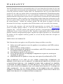
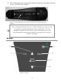
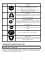
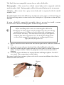
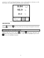
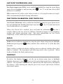
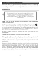
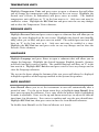
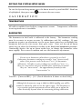
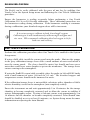
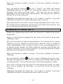
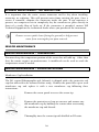
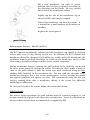
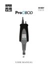
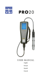
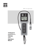
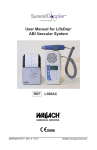
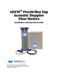
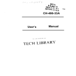
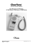
PRO20 USER MANUAL English Français Español Deutsch Item # 605597 Rev A Drawing # A605597 May 2008 ©2008 YSI Incorporated. The YSI logo is a registered trademark of YSI Incorporated. Teflon is a registered trademark of E. I. du Pont de Nemours and Company. CONTENTS Warranty .....................................................................................................1 Introduction................................................................................................2 Getting Started ............................................................................................2 Initial Inspection................................................................................2 Battery Installation.............................................................................2 Keypad................................................................................................3 Connecting the Sensor and Cable .....................................................4 Membrane Installation ......................................................................7 Backlight.............................................................................................7 Powering Off ......................................................................................7 Run Screen .........................................................................................7 Navigation ..........................................................................................8 First Power On ...................................................................................9 System Setup Menu ..................................................................................10 DO Local%.......................................................................................10 Last Digit Suppression (LDS)..........................................................11 One Touch Calibration (One Touch Cal) ......................................11 Audio ................................................................................................11 Contrast............................................................................................11 Sensor Type ......................................................................................12 Membrane Type...............................................................................13 Auto Stable .......................................................................................14 DO Units ..........................................................................................14 Temperature Units...........................................................................15 Pressure Units ..................................................................................15 Language...........................................................................................15 Auto Shutoff.....................................................................................15 Resetting the System Setup Menu to Factory Default ...................16 Exiting the System Setup Menu ......................................................17 Calibration ................................................................................................17 Temperature.....................................................................................17 Barometer.........................................................................................17 Dissolved Oxygen.............................................................................18 Salinity Compensation Calibration ................................................21 Taking Measurements ..............................................................................22 Saving and Viewing data...........................................................................22 Saving Data.......................................................................................22 Viewing and Erasing Saved Data – Data mode ..............................23 Principles of Operation ............................................................................25 Care, Maintenance, and Storage ..............................................................26 General Maintenance.......................................................................26 Sensor Maintenance.........................................................................28 Sensor Storage ..................................................................................32 Troubleshooting........................................................................................33 Specifications.............................................................................................35 Accessories/Part Numbers........................................................................36 Declaration of Conformity.......................................................................37 Recycling....................................................................................................38 Contact Information.................................................................................39 Ordering & Technical Support........................................................39 Service Information .........................................................................39 WARRANTY The YSI Pro20 Instrument is warranted for three (3) years from date of purchase by the end user against defects in materials and workmanship, exclusive of batteries and any damaged caused by defective batteries. Pro20 cables are warranted for two (2) years from date of purchase by the end user against defects in material and workmanship. Pro20 Polarographic sensors are warranted for one (1) year and Galvanic sensors are warranted for six (6) months from date of purchase by the end user against defects in material and workmanship. Pro20 instruments, cables & probes are warranted for 90 days from date of purchase by the end user against defects in material and workmanship when purchased by rental agencies for rental purposes. Within the warranty period, YSI will repair or replace, at its sole discretion, free of charge, any product that YSI determines to be covered by this warranty. To exercise this warranty, call your local YSI representative, or contact YSI Customer Service in Yellow Springs, Ohio at +1 937 767-7241, 800-897-4151 or visit www.ysi.com (Support tab). Send the product and proof of purchase, transportation prepaid, to the Authorized Service Center selected by YSI. Repair or replacement will be made and the product returned, transportation prepaid. Repaired or replaced products are warranted for the balance of the original warranty period, or at least 90 days from date of repair or replacement. LIMITATION OF WARRANTY This Warranty does not apply to any YSI product damage or failure caused by: 1) failure to install, operate or use the product in accordance with YSI's written instructions; 2) abuse or misuse of the product; 3) failure to maintain the product in accordance with YSI's written instructions or standard industry procedure; 4) any improper repairs to the product; 5) use by you of defective or improper components or parts in servicing or repairing the product; 6) modification of the product in any way not expressly authorized by YSI. THIS WARRANTY IS IN LIEU OF ALL OTHER WARRANTIES, EXPRESSED OR IMPLIED, INCLUDING ANY WARRANTY OF MERCHANTABILITY OR FITNESS FOR A PARTICULAR PURPOSE. YSI's LIABILITY UNDER THIS WARRANTY IS LIMITED TO REPAIR OR REPLACEMENT OF THE PRODUCT, AND THIS SHALL BE YOUR SOLE AND EXCLUSIVE REMEDY FOR ANY DEFECTIVE PRODUCT COVERED BY THIS WARRANTY. IN NO EVENT SHALL YSI BE LIABLE FOR ANY SPECIAL, INDIRECT, INCIDENTAL OR CONSEQUENTIAL DAMAGES RESULTING FROM ANY DEFECTIVE PRODUCT COVERED BY THIS WARRANTY. 1 INTRODUCTION Thank you for purchasing the YSI Pro20, an instrument from the YSI Professional Series product family. The Pro20 features an impact resistant and waterproof (IP67) case, backlit display, user-selectable sensor options, internal barometer, and a rugged, rubber over-mold case. The Pro20 provides valuable instructions and prompts near the bottom of the display that will guide you through operation and use. However, reading the entire manual is recommended for a better understanding of the Pro20’s features. L The Pro20 can not communicate to a PC via a Pro Plus communications saddle. Connecting the Pro20 to a communication saddle may cause erratic instrument behavior. GETTING STARTED INITIAL INSPECTION Carefully unpack the instrument and accessories and inspect for damage. Compare received parts with materials listed on the packing list. If any parts or materials are missing or damaged, contact YSI Customer Service at 800-897-4151 (+1-937-767-7241) or the Authorized YSI distributor from whom the instrument was purchased. BATTERY INSTALLATION This instrument requires 2 alkaline C-cell batteries. Under normal conditions, battery life is approximately 400 hours at room temperature without using the will blink in the lower, left corner of the back light. A battery symbol display to indicate low batteries when approximately 1 hour of battery life remains. To install or replace the batteries: 1) 2) 3) 4) Turn the instrument off and flip over to view the battery cover on the back. Unscrew the four captive battery cover screws. Remove the battery cover, and remove the old batteries if necessary. Install the new batteries, ensuring correct polarity alignment (Figure 1). 2 5) Place the battery cover on the back of the instrument and tighten the four screws. Do NOT over-tighten. Figure 1, Pro20 with battery cover removed. Note battery symbols indicating polarities. The waterproof instrument case is sealed at the factory and is not to be opened, except by authorized service technicians. Do not attempt to separate the two halves of the instrument case as this may damage the instrument, break the waterproof seal, and will void the warranty. L KEYPAD 2 3 1 4 5 6 Figure 2, keypad 3 Number Key Description 1 Calibrate Press and hold for 3 seconds to calibrate. Initiates One Touch Calibration. Opens Calibrate menu from the run screen if One Touch Calibration is disabled. 2 Up Arrow Use to navigate through menus, to navigate through box options at the bottom of the run screen, and to increase numeric inputs. 3 Power and Backlight Press once to turn instrument on. Press a second time to turn backlight on. Press a third time to turn backlight off. Press and hold for 3 seconds to turn instrument off. 4 Menu Use to enter the System Setup menu from the run screen. 5 Enter Press to confirm entries and selections. 6 Down Arrow Use to navigate through menus, to navigate through box options at the bottom of the run screen, and to decrease numeric inputs. CONNECTING THE SENSOR AND CABLE CONNECTING THE SENSOR “Sensor” refers to the removable portion or electrode sensing portion of the cable assembly, i.e. the dissolved oxygen sensor. “Bulkhead” refers to the portion of the cable with the single-pin connector (Figure 3). 4 The Pro20 has two compatible sensors for use with a field cable: Polarographic – This sensor has a black sensor body and is engraved with the model number 2003. Polarographic will be abbreviated Polaro in the instrument. Galvanic – This sensor has a grey sensor body and is engraved with the model number 2002. For information about the differences on the two sensor types, see Sensor Type in the System Setup menu section and/or the Principles of Operation section of this manual. If using a ProBOD sensor/cable assembly, there is no need to install a sensor because it has a built in Polarographic dissolved oxygen sensor. L Before installing either sensor or connecting the cable to the instrument, the Sensor Type must be configured for the sensor being installed/connected. Failure to do this may result in damage not covered under warranty. The instrument will step you through this setup the first time it is powered on. See the System Setup menu section of this manual for instructions on configuring the Sensor Type after the first power on. 1) Ensure both the sensor connector and sensor port on the cable are clean and dry. 2) Grasp the sensor with one hand and the cable bulkhead in the other. 3) Push the sensor into the connector on the cable until it is firmly seated and only 1 o-ring is visible. Failure to properly seat the sensor may result in damage. 4) Twist the sensor clockwise to engage threads and finger tighten. Do NOT use a tool. This connection is water-tight. For more detailed instructions, please refer to the sensor installation sheet that is included with each sensor. Sensor Bulkhead Figure 3 5 CONNECTING THE CABLE The Pro20 is designed for field and laboratory use. It is compatible with two different cable options: 1) The field rugged cable is available in standard lengths of 1, 4, 10, 20, 30, and 100 meters with special lengths available between 30 and 100 meters. This cable has a built in temperature sensor and includes a port for the dissolved oxygen sensor. 2) The ProBOD is a 1 meter probe/cable assembly with built in Polarographic dissolved oxygen and temperature sensors. It has an AC powered motor for sample stirring and is designed to fit into a 300 ml BOD bottle. To connect the cable, align the keys in the cable connector to the slots in the instrument connector. Push together firmly and then twist the outer ring until it locks into place (Figure 4). This connection is water-proof. Figure 4, Note the keyed connector. L When disconnected, the sensor and cable’s sensor connectors are NOT water-proof. Do not submerge the cable without a sensor installed. When disconnected, the cable’s instrument connector and the connector on the instrument maintain a waterproof, IP-67 rating. 6 MEMBRANE INSTALLATION The dissolved oxygen sensor is shipped with a dry, protective red cap that will need to be removed before using. It is very important to put a new membrane with electrolyte solution on the sensor after removing the red cap. Prepare the membrane solution according to the instructions on the bottle. After mixing, allow the solution to sit for 1 hour. This will help prevent air bubbles from later developing under the membrane. Ensure you are using the correct electrolyte solution for the correct sensor. Galvanic sensors utilize electrolyte with a light blue label and Polarographic sensors utilize electrolyte with a white label. The Dissolved Oxygen sensor is supplied with cap membranes specific to the sensor type ordered (Polarographic or Galvanic). 5913 and 5914 membrane kits are for Galvanic sensors and the 5908 and 5909 membrane kits are for Polarographic sensors. Remove and discard or save the red protective cap. Thoroughly rinse the sensor tip with distilled or deionized water. Fill the cap membrane 3⁄4 full of electrolyte solution, then tap the cap with a finger to release any trapped air. Be careful not to touch the membrane portion of the cap. Thread the membrane cap onto the sensor, moderately tight. Do not use a tool. It’s typical for some of the electrolyte solution to spill over. It is best to allow the new cap to remain on a new sensor overnight before trying to calibrate. For detailed instructions on changing a membrane cap, see the Care, Maintenance, and Storage section of this manual. BACKLIGHT Once the instrument is on, pressing power/backlight key will turn on the display backlight. The backlight will remain on until the key is pressed again or after two minutes of not pressing any key on the keypad. POWERING OFF To turn the instrument off, press and hold the power/backlight seconds. key for three RUN SCREEN Press the power/backlight key to turn the instrument on. The instrument will run through a self test and briefly display a splash screen with system information before displaying the main run screen (Figure 5). The first time the Pro20 is 7 turned on, it will step through language, sensor, and membrane selections; see the First Power On section of this manual for more information. 730.3 mmHg 8.04 95.9 % 24.2 °C 0.0 ppt mg/L SAVE DATA Figure 5, example of main run screen with Save highlighted. NAVIGATION The up and down of the Pro20. arrow keys allow you to navigate through the functions NAVIGATING IN THE RUN SCREEN When in the run screen, the up and down arrow keys will move the highlighted box along the bottom options. Once a box is highlighted, press enter to access the highlighted option. 8 Description of run screen box functions from left to right: Option Description Barometer reading Highlight and press enter to calibrate the barometer Salinity compensation value Highlight and press enter compensation value SAVE DATA to adjust salinity Highlight and press enter to save current data to memory Highlight and press enter to view and/or erase saved data NAVIGATING IN THE SYSTEM SETUP MENU When in the System Setup menu, the up and down arrow keys will move the highlighted bar up and down the system setup options. See the System Setup menu section of this manual for more information about these options. FIRST POWER ON The instrument will step through an initial configuration when powered on for the first time. This will set the language, sensor, and membrane options. Use the up or down arrow keys to highlight the appropriate language, sensor, and membrane, then press enter to confirm (Figures 6, 7, and 8). The Sensor Type must be configured for the sensor installed. Failure to do this may result in damage not covered under warranty. If an incorrect option is selected, it may be changed in the System Setup menu. Select Language: 7 English Français Español Deutsch Use ST to select Language Press to confirm Figure 6, Language selection Select Sensor Type: 7 Polaro (black) Galvanic (grey) Use ST to select sensor type Press to confirm Figure 7, Sensor selection 9 Select Membrane Type: 71.25 (Yellow) 2.0 (Blue) Use ST to select membrane Press to confirm Figure 8, Membrane selection After selecting a language, sensor, and membrane, the run screen will appear. The next time the instrument is powered up the run screen will appear immediately after the self check. If the sensor type or membrane type is changed, ensure that it updated in the System Setup menu. SYSTEM SETUP MENU Press the menu key to access the following System Setup functions. The System Setup menu contains multiple screens which are notated as ‘pages’. The current page is indicated on the display, figure 9. DO LOCAL% DO Local% can be enabled or disabled by using the up or down arrow keys to highlight it and then pressing enter. An ‘X’ in the box next to DO Local% indicates it is enabled (Figure 9). 7 DO Local% LDS One Touch Cal Audio Contrast Sensor Type Membrane Type page 1 of 2 ESC 4 Exit Reset Figure 9, DO %Local is enabled. When DO Local% is enabled, DO% values will be expressed as %L on the run screen. DO Local% allows for localized dissolved oxygen measurements. This sets the DO% calibration value to 100% regardless of the altitude or barometric pressure. When DO Local% is enabled, the Pro20 will factor in the barometric pressure on each measurement. For example, if the barometric pressure changes, the DO %L reading would remain constant in air-saturated water or in water-saturated air. Local DO is ideal for EU compliance. 10 LAST DIGIT SUPPRESSION (LDS) Last Digit Suppression (LDS) can be enabled or disabled by using the up or down arrow keys to highlight it and pressing enter . An ‘X’ in the box next to LDS indicates it is enabled. LDS rounds the DO value to the nearest tenth; i.e. 8.25 mg/L becomes 8.3 mg/L. LDS is automatically disabled during calibrations. ONE TOUCH CALIBRATION (ONE TOUCH CAL) One Touch Calibration can be enabled or disabled by using the up or down arrow keys to highlight One Touch Cal and pressing enter . An ‘X’ in the box next to One Touch indicates it is enabled. key for 3 When One Touch Cal is enabled, press and hold the calibration seconds while in the run screen to calibrate Dissolved Oxygen to the barometer reading and salinity correction value. For more information on One Touch Calibration, see the Calibration section of this manual. AUDIO Audio can be enabled or disabled by using the up or down arrow keys to highlight Audio and pressing enter . When enabled, there will be an ‘X’ in the box next to Audio. When Audio is enabled, the Pro20 will beep twice to indicate stability when Auto Stable is enabled. The instrument will also beep when a key is pressed. When Audio is disabled, the Pro20 will not beep. CONTRAST To adjust the display Contrast, use the up or down arrow keys to highlight . Next, use the up or down arrow keys to adjust the Contrast, then press enter contrast. The up arrow will darken the contrast and the down arrow will lighten the contrast. After adjusting the contrast, press enter to save and exit the Contrast adjustment option. 11 EMERGENCY CONTRAST ADJUSTMENT If necessary, there is an alternate method of adjusting the contrast. To adjust the contrast, press and hold the menu key, then press the up arrow key to darken the contrast or press the down arrow key to lighten the contrast. SENSOR TYPE L The instrument’s Sensor Type must be configured for the sensor installed. Failure to do this may result in damage not covered under warranty. If you observe readings very close to 0 or extremely high readings, i.e. 600%, your Sensor Type setting may be set incorrectly. Sensor Type sets the type of oxygen sensor being used; either Polarographic (black) or Galvanic (grey). to Use the up or down arrow keys to highlight Sensor Type, then press enter open a submenu. Highlight the sensor type corresponding to the sensor installed on the cable and press enter to confirm. The enabled sensor type will have an ‘X’ in the box next to it. Use the down arrow key to highlight the ESC – Exit, then press enter to save changes and to close the sensor submenu. If using a ProBOD sensor/cable assembly, the sensor type should be set to polarographic. The Pro20 has two compatible sensors for use with a field cable: Polarographic – This sensor has a black sensor body and is engraved with the model number 2003. Polarographic will be abbreviated Polaro in the instrument. Galvanic – This sensor has a grey sensor body and is engraved with the model number 2002. In terms of physical configuration, membrane material, and general performance, YSI Professional Series Galvanic dissolved oxygen sensors are exactly like the Professional Series Polarographic sensors. The advantage of using Galvanic sensors is convenience. Galvanic sensors provide for an instant-on sensor without the need for warm-up time but this affects the life of the sensor. Polarographic sensors last longer and have a longer warranty but require a 5-15 minute warm-up time before use or calibration. 12 MEMBRANE TYPE Membrane Type sets the type of membrane used on the dissolved oxygen sensor; either 1.25 PE (Yellow) or 2.0 PE (blue). Use the up or down arrow keys to to open the membrane submenu. highlight Membrane Type and press enter Highlight the membrane type corresponding to the membrane installed on the sensor and press enter to confirm. The enabled membrane type will have an ‘X’ in the box next to it. Use the down arrow key to highlight the ESC – Exit box and press enter to save changes and to close the membrane submenu. The dissolved oxygen sensor is supplied with membranes specific to the sensor type ordered and are color coded as described in the following tables. Galvanic Membrane Kits Item Color Material Description 5913 Yellow 1.25 mil polyethylene Faster response time and less flow dependence than traditional Teflon® membranes 5914 Blue 2.0 mil polyethylene Less flow dependence than 1.25 mil but somewhat slower response Polarographic Membrane Kits Item Color Material Description 5908 Yellow 1.25 mil polyethylene Faster response time and less flow dependence than traditional Teflon® membranes 5909 Blue 2.0 mil polyethylene Less flow dependence than 1.25 mil but somewhat slower response Selecting a Dissolved Oxygen Membrane Membrane Type Flow Dependence After 4 Minutes Typical Response Time to 95% 5913, 5908 - Yellow 25% 8 seconds 5914, 5909 – Blue 18% 17 seconds 13 AUTO STABLE Auto Stable utilizes preset values to indicate when a reading is stable. The preset values are adjustable in the System Setup menu. The user can input a % change in dissolved oxygen readings (0.0 to 1.9) over ‘x’ amount of time in seconds (3-19). to expand the submenu. Use the up or Highlight Auto Stable and press enter down arrow keys to highlight the DO% Change or seconds (secs) input field, then press enter to make the highlighted field adjustable. Use the up and down arrow keys to adjust the selected value, then press enter to confirm changes. Once you have confirmed any changes, highlight the ESC-Exit box and press enter to close the Auto Stable submenu. To disable Auto Stable, set the DO% Change input to 0.0. will display next to the dissolved oxygen When Auto Stable is enabled, a value on the run screen and blink during stabilization. When the dissolved oxygen value has stabilized based on the Auto Stable settings, the and the instrument will beep twice if Audio is turned on. will display steadily DO UNITS Highlight DO Units and press enter to open a submenu that will allow you to select the dissolved oxygen units displayed on the run screen. Highlight the desired unit(s) and press enter to enable or disable. An enabled dissolved oxygen unit will have an ‘X’ in the box next to it. Highlight the ESC-Exit box and press enter to save any changes and to close the DO units submenu. There are three options for displaying dissolved oxygen: mg/L will show DO readings in milligrams per liter on a scale from 0 to 50 mg/L. ppm (parts per million) is equivalent to mg/L and will show the DO reading on a scale from 0 to 50 ppm. % will show DO readings in a percent scale from 0 to 500%. This value will be expressed %L when DO Local% is enabled. Both % or %L and mg/L or ppm can be displayed simultaneously on the screen. 14 TEMPERATURE UNITS Highlight Temperature Units and press enter to open a submenu that will allow you to change the temperature units displayed in the run screen. Highlight the desired unit (Celsius or Fahrenheit) and press enter to enable. The enabled temperature unit will have an ‘X’ in the box next to it. Only one unit may be enabled at a time. Highlight the ESC-Exit box and press enter to save any changes and to close the Temperature Units submenu. PRESSURE UNITS Highlight Pressure Units and press enter to open a submenu that will allow you to change the units displayed on the run screen. Highlight the desired unit (mmHg, inHg, mbar, psi, or kPa) and press enter to enable. The enabled pressure unit will have an ‘X’ in the box next to it. Only one unit may be enabled at a time. Highlight the ESC-Exit box and press enter to save any changes and to close the Pressure Units submenu. LANGUAGE Highlight Language and press Enter to open a submenu that will allow you to change the language. Highlight the desired language (English, Spanish, German, or French) and press enter to enable. The enabled language will have an ‘X’ in the box next to it. Highlight ESC-Exit box and press enter to save any changes and to close the Language submenu. The text in the boxes along the bottom of the run screen will always be displayed in English regardless of the language enabled in the System Setup menu. AUTO SHUTOFF Auto Shutoff allows you to set the instrument to turn off automatically after a period of time. Use the up or down arrow keys to highlight Auto Shutoff, then press enter to open the submenu. Press enter while the minute field is highlighted to make it adjustable. Next, use the up and down arrow keys to adjust the shut off time from 0 to 60 minutes. Press enter to confirm and save the new shutoff time. Highlight ESC-Exit box, then press enter to close the Auto Shutoff submenu. To disable Auto Shutoff, set the Time in Minutes to 0 (zero). 15 RESETTING THE SYSTEM SETUP MENU TO FACTORY DEFAULT To reset the Pro20 settings to factory default, press the down arrow key until the Reset - 4 box is highlighted, then press enter. The instrument will ask you to confirm the reset. Highlight Yes and press enter to continue with the reset or highlight No and press enter to cancel the reset. A Factory Reset will not affect data saved in the unit’s memory. The following will be set in the Pro20 after performing a factory reset: Parameter Reset Defaults Temperature Units o Dissolved Oxygen Units mg/L and % Pressure Units mmHg Dissolved Oxygen Sensor Type Last Setting Confirmed Membrane Type Last Setting Confirmed Salinity Compensation Value 0.0 ppt DO Local% Off One Touch Cal On Display Contrast Set to mid range Auto Shutoff 30 minutes Auto Stable Off (0.0 % Change and 10 secs) LDS (Last Digit Suppression) Off Audio On Language English Dissolved Oxygen Calibration Reset to factory default, 100% for enabled membrane and sensor* Barometer Calibration Reset to factory default* C *It is recommended to perform a barometer and dissolved oxygen calibration after performing a reset. 16 EXITING THE SYSTEM SETUP MENU To exit the System Setup menu, press the down arrow key until the ESC - Exit box is highlighted, then press enter to return to the run screen. CALIBRATION TEMPERATURE All cable assemblies have built-in, temperature sensors. Temperature calibration is not required nor is it available. BAROMETER The barometer in the Pro20 is calibrated at the factory. The barometer reading must be accurate to ensure accurate % calibrations and DO readings. If your barometer requires an adjustment, use the up or down arrow keys to highlight the barometer box on the run screen, then press enter. Next, use the up or down arrow keys to adjust the barometer reading to the local, true barometric pressure. Continually depress the up or down arrow keys to change the barometer value more rapidly. Press enter to confirm and save the barometer adjustment. L Do not use a barometer value that is corrected to sea level. Laboratory barometer readings are usually “true” (uncorrected) values of air pressure and can be used “as is” for barometer calibration. Weather service readings are usually not “true”, i.e., they are corrected to sea level, and therefore cannot be used until they are “uncorrected”. An approximate formula for this “uncorrection” is: True BP = [Corrected BP] – [2.5 * (Local Altitude in ft above sea level/100)] L Although the barometer range is 400.0 to 999.9 mmHg, you will be unable to adjust the value across the entire range. The barometer is very accurate and the instrument will not allow you to adjust the value drastically beyond what it is measuring during calibration. 17 DISSOLVED OXYGEN The Pro20 can be easily calibrated with the press of one key by enabling One Touch Cal in the System Setup menu and following the One Touch Calibration procedure. Ensure the barometer is reading accurately before performing a One Touch Calibration, DO %, or DO Local% calibration. These calibration procedures use the barometer reading during calibration. If the barometer reading is erroneous during a calibration, your dissolved oxygen values will be inaccurate. L It is not necessary to calibrate in both % and mg/L or ppm. Calibrating in % will simultaneously calibrate mg/L and ppm and vice versa. YSI recommends calibrating dissolved oxygen in % for both ease and accuracy. ONE TOUCH CALIBRATION Perform this calibration procedure when One Touch Cal is enabled in the System Setup menu. If using a field cable, install the sensor guard onto the probe. Moisten the sponge in the grey calibration/storage sleeve with a small amount of water and install it over the sensor guard. The sleeve should be moist, but should not have excess water that could cause water droplets to get on the membrane. The storage sleeve ensures venting to the atmosphere. If using the ProBOD sensor/cable assembly, place the probe in 300 ml BOD bottle with a small amount of water (1/8 inch or 0.3 cm). The dissolved oxygen and temperature sensors should not be immersed in water. If the calibration/storage sleeve is not available, substitute with a chamber of 100% relative humidity, vented to the atmosphere (not completely sealed). Power the instrument on and wait approximately 5 to 15 minutes for the storage chamber to become completely saturated and to allow the sensor to stabilize if using a Polarographic sensor. If using a Galvanic sensor, wait approximately 5 to 10 minutes for the chamber to become completely saturated. Auto Shutoff time should be disabled or set to at least 20 minutes, see System Setup menu for more information on adjusting the Auto Shutoff. 18 Ensure the barometer reading is accurate. If necessary, perform a barometer calibration. key for 3 seconds. The Pro20 will indicate Press and hold the Calibrate Calibrating %DO on the display and automatically calibrate the sensor to the barometer and salinity correction values. This may take up to 2 minutes depending on the age of the sensor and membrane. You may press the Cal key at this time to cancel the calibration. Calibration Successful will display for a few seconds to indicate a successful calibration and then the instrument will return to the run screen. If the calibration is unsuccessful, an error message will display on the screen. Press the Cal key to exit the calibration error message and return to the run screen. See the Troubleshooting guide for possible solutions. CALIBRATING IN PERCENT (DO %) Perform this calibration procedure when One Touch Cal is disabled in the System Setup menu. Prepare a 100% humid environment for the sensor as described in the previous calibration section. Power the instrument on and wait approximately 5 to 15 minutes for the storage chamber to become completely saturated and to allow the sensor to stabilize if using a Polarographic sensor. If using a Galvanic sensor, wait approximately 5 to 10 minutes for the chamber to become completely saturated. Auto Shutoff time should be disabled or set to at least 20 minutes, see System Setup menu for more information on adjusting the Auto Shutoff. Ensure the barometer reading is accurate. If necessary, perform a barometer calibration. key for 3 seconds. Highlight % and press enter. Press and hold the Calibrate The Pro20 will display the current DO% and temperature readings along with the % calibration value. The % calibration value is based on the barometer reading. Wait at least 3 seconds, then, once the DO% and temperature readings are stable, press enter to complete the calibration. Or, press the Cal key to cancel the calibration. Calibration Successful will display for a few seconds to indicate a successful calibration and then the instrument will return to the run screen. 19 If the calibration is unsuccessful, an error message will display on the screen. Press the Cal key to exit the calibration error message and return to the run screen. See the Troubleshooting guide for possible solutions. CALIBRATING IN PERCENT (DO LOCAL% ENABLED) Perform this calibration procedure when DO Local% is enabled in the System Setup menu. Prepare a 100% humid environment for the sensor as described in the One Touch Calibration section. Power the instrument on and wait approximately 5 to 15 minutes for the storage chamber to become completely saturated and to allow the sensor to stabilize if using a Polarographic sensor. If using a Galvanic sensor, wait approximately 5 to 10 minutes for the chamber to become completely saturated. Auto Shutoff time should be disabled or set to at least 20 minutes, see System Setup menu for more information on adjusting the Auto Shutoff. Ensure the barometer reading is accurate. If necessary, perform a barometer calibration. key for 3 seconds. %Local will be automatically Press and hold the Calibrate highlight, press enter. The Pro20 will display the current DO% and temperature readings along with the % calibration value. The % calibration value will always be 100% for DO Local%. Wait at least 3 seconds, then, once the DO% and temperature readings are stable, press enter to complete the calibration. Or, press the Cal key to cancel the calibration. Calibration Successful will display for a few seconds to indicate a successful calibration and then the instrument will return to the run screen. If the calibration is unsuccessful, an error message will display on the screen. Press the Cal key to exit the calibration error message and return to the run screen. See the Troubleshooting guide for possible solutions. CALIBRATING IN MG/L Power the instrument on and place the sensor into a sample that has been titrated to determine the dissolved oxygen concentration. Continuously stir or move the probe through the sample at a rate of at least ½ foot per second (16 cm per second) during the entire calibration process. A stir plate may be helpful in this calibration. 20 Allow the dissolved oxygen and temperature readings to stabilize. This may take 5 to 15 minutes, depending on the age of the instrument, type of sensor, and condition of the sensor. Press the Calibrate key. Highlight mg/L and press enter. Use the up and down arrow keys to adjust the mg/L reading to the value of the titrated sample. Press enter to confirm the value and calibrate or press the Cal key to cancel the calibration. Calibration Successful will display for a few seconds to indicate a successful calibration and then the instrument will return to the run screen. If the calibration is unsuccessful, an error message will display on the screen. Press the Cal key to exit the calibration error message and return to the run screen. See the Troubleshooting guide for possible solutions. SALINITY COMPENSATION CALIBRATION The Pro20 uses a user inputted salinity value in ppt (parts per thousands) to compensate dissolved oxygen mg/L values. The salinity compensation value entered in the Pro20 should be the salinity value of the water you are testing. To adjust the salinity compensation value, use the up or down arrow keys to highlight the salinity box on the run screen, and then press enter (Figure 10). Next, use the up or down arrow keys to adjust the salinity compensation value to the salinity of the water you are testing. You may enter a value between 0.0 and 70.0 parts per thousand (ppt). Press enter to confirm and to save the new salinity compensation value. The salinity compensation value can be adjusted any time without the need to recalibrate dissolved oxygen. 6.58 95.9 mg/L % 24.2 °C 729.7 35.0 mmHg ppt SAVE DATA Figure 10, Salinity box highlighted. 21 TAKING MEASUREMENTS Before taking measurements, be sure the instrument has been calibrated to ensure the most accurate readings. Turn the instrument on and wait 5-15 minutes if using a polarographic sensor. If using a field cable/sensor, install the sensor guard to protect the sensor and membrane. Place the probe in the sample to be measured and give the probe a quick shake to release any air bubbles. Allow the temperature readings to stabilize. Next, stir the probe in the sample to overcome the stirring dependence of the dissolved oxygen sensor. You must provide at least 6 inches (16 cm) per second of water movement. Once the values plateau and stabilize you may record the measurement and/or store the data set. The dissolved oxygen reading will drop over time if stirring is ceased. If placing the DO sensor into a stream or fast flowing waters it is best to place it perpendicular to the flow and NOT facing into the flow. If using the DO sensor in an aeration tank/basin it is helpful to make sure bubbles do not burst on the membrane. This may cause unstable readings to occur. You should be able to prevent this by pointing the sensor upwards so it’s facing the sky and twist tying, zip tying, or rubber banding the bulkhead to the cable. Essentially making a simple curve to the cable without bending or breaking the cable will allow you to lower the sensor into the aeration tank while the sensor points skyward and the bubbles are no longer bursting on the membrane surface. SAVING AND VIEWING DATA The Pro20 can store 50 data sets in non-volatile memory for later viewing. A data set includes the values currently on the display, i.e. temperature in Celsius or Fahrenheit and dissolved oxygen in % and/or mg/L or ppm. Each data point is referenced with a data set number, 01 through 50. L The Pro20 can not communicate to a PC via a Pro Plus communications saddle. Connecting the Pro20 to a communication saddle may cause erratic instrument behavior. SAVING DATA From the run screen, use the up or down arrow keys to highlight the Save box and press enter to save the current readings. The instrument will indicate the data set is saved and display the saved data set’s number (Figure 11). 22 6.58 95.9 24.2 mg/L % °C Data set 01 saved 729.7 35.0 mmHg ppt SAVE DATA Figure 11, Data set saved The instrument will display ‘Memory Full’ if all 50 data sets have been saved and you attempt to save another data set. VIEWING AND ERASING SAVED DATA – DATA MODE Data mode allows you to view and erase saved data. From the run screen, use the up or down arrow keys to highlight Data and press enter to access data mode. Note that the function boxes at the bottom of the display are different in data mode (Figure 12). 6.58 95.9 mg/L % 24.2 °C Data set 01 ESC Exit Erase Figure 12, Data mode 23 DATA VIEWING DATA Once in data mode, use the up and down arrow keys to view saved data sets in sequential order or press enter to access the bottom functions. After accessing the bottom functions, highlight the Data box and press enter to regain access to viewing data. The data set that is displayed will be indicated by the data set number, 01 through 50. ERASING DATA While viewing saved data, press the enter key to access the function boxes at the bottom of the display. Next, use the up or down arrow keys to highlight Erase, then press enter. The instrument will give you the option to erase one or all data sets (Figure 13). Erase Data Set Erase All Sets ESC Exit Figure 13, erasing data Use the up or down arrow key to select Erase Data Set, Erase All Sets, or the ESCExit function box, then press enter to confirm. Select ESC-Exit and press enter to exit erase mode without erasing any data. Select Erase Data Set and press enter to erase the data set that was displayed before entering erase mode. For example, if data set 12 was displayed before entering erase mode, and Erase Data Set is selected, Data Set 12 will be erased from memory and the sets AFTER that number will move up to keep them sequential. So, if there were 15 records and number 12 is erased then 13 becomes 12, 14 becomes 13, and 15 becomes 14. The instrument will return to data mode after erasing one data set. Select Erase All Data Sets and press enter to clear the Pro20 memory and return to data mode. 24 EXITING DATA MODE While in Data mode, press enter to access the bottom functions. Next, highlight the ESC-Exit box and press enter to return to the run screen. PRINCIPLES OF OPERATION The polarographic sensor consists of a silver body as the anode and a circular gold cathode embedded in the end. The galvanic sensor consists of a zinc anode and silver cathode. The polarographic sensor requires an applied voltage for operation while the galvanic sensor electrode potentials are dissimilar enough to reduce oxygen with applied voltage. Both sensors have a thin semi-permeable membrane, stretched over the sensor, which isolates the electrodes from the environment, while allowing gases to enter. In operation, this end of the sensor is filled with a solution of electrolyte containing a small amount of surfactant to improve wetting action. When a polarizing voltage is applied to the polarographic sensor electrodes, oxygen that has passed through the membrane reacts at the cathode causing a current to flow. This same reaction takes place with the galvanic sensor without the applied voltage. For both polarographic and galvanic DO sensors, oxygen diffuses through the membrane at a rate proportional to the oxygen pressure difference across it. Since oxygen is rapidly consumed at the cathode, it can be assumed that the oxygen pressure inside the membrane is zero. Hence, the amount of oxygen diffusing through the membrane is proportional to the absolute pressure of oxygen outside the membrane. If the oxygen pressure increases, more oxygen diffuses through the membrane and more current flows through the sensor. A lower pressure results in less current. 25 CARE, MAINTENANCE, AND STORAGE This section describes the proper procedures for care, maintenance and storage of the sensors. The goal is to maximize their lifetime and minimize down-time associated with improper sensor usage. GENERAL MAINTENANCE GENERAL MAINTENANCE - O-RINGS The instrument utilizes o-rings as seals to prevent water from entering the battery compartment and the sensor ports. Following the recommended procedures will help keep your instrument functioning properly. If the o-rings and sealing surfaces are not maintained properly, it is possible that water can enter the battery compartment and/or sensor ports of the instrument. If water enters these areas, it can severely damage the battery terminals or sensor ports causing loss of battery power, false readings and corrosion to the sensors or battery terminals. Therefore, when the battery compartment lid is removed, the oring that provides the seal should be carefully inspected for contamination (e.g. debris, grit, etc.) and cleaned if necessary. The same inspection should be made of the o-rings associated with the dissolved oxygen sensor connector when it is removed. If no dirt or damage to the o-rings is evident, then they should be lightly greased without removal from their groove. However, if there is any indication of damage, the o-ring should be replaced with an identical o-ring. At the time of o-ring replacement, the entire o-ring assembly should be cleaned. To remove the o-rings: Use a small, flat-bladed screwdriver or similar blunt-tipped tool to remove the oring from its groove. Check the o-ring and the groove for any excess grease or contamination. If contamination is evident, clean the o-ring and nearby plastic parts with lens cleaning tissue or equivalent lint-free cloth. Alcohol can be used to clean the plastic parts, but use only water and mild detergent on the o-ring itself. Also, inspect the o-rings for nicks and imperfections. 26 L Using alcohol on o-rings may cause a loss of elasticity and may promote cracking. Do not use a sharp object to remove the o-rings. Damage to the oring or the groove may result. Before re-installing the o-rings, make sure to use a clean workspace, clean hands, and avoid contact with anything that may leave fibers on the o-ring or grooves. Even a very small amount of contamination (hair, grit, etc.) may cause a leak. To re-install the o-rings: Place a small amount of o-ring grease between your thumb and index finger. (More grease is NOT BETTER!) Draw the o-ring through the grease while pressing the fingers together to place a very light covering of grease to the o-ring. Place the o-ring into its groove making sure that it does not twist or roll. Use the previously grease-coated finger to once again lightly go over the mating surface of the o-ring. L Do not over-grease the o-rings. The excess grease may collect grit particles that can compromise the seal. Excess grease can also cause the waterproofing capabilities of the o-ring to diminish, potentially causing leaks. If excess grease is present, remove it using a lens cloth or lint-free cloth. 27 GENERAL MAINTENANCE – DO SENSOR PORT It is important that the entire sensor connector end be dry when installing, removing, or replacing. This will prevent water from entering the port. Once a sensor is removed, examine the connector inside the port. If any moisture is present, use compressed air to completely dry the connector or place directly in front of a steady flow of fresh air. If the connector is corroded, contact YSI Technical Support or the Authorized dealer where you purchased the instrument. L Remove sensors upside down (facing the ground) to help prevent water from entering the port upon removal. SENSOR MAINTENANCE SENSOR MAINTENANCE - TEMPERATURE You must keep the temperature portion of the sensor free of build up. Other than that, the sensor requires no maintenance. A toothbrush can be used to scrub the temperature sensor if needed. SENSOR MAINTENANCE – DISSOLVED OXYGEN Membrane Cap Installation The DO sensor (Polarographic and Galvanic) is shipped with a dry, protective red cap that will need to be removed before using. Remove the protective cap or used membrane cap and replace it with a new membrane cap following these instructions: Remove the sensor guard to access the sensor tip. Remove the protective red cap or unscrew and remove any old membrane cap by holding the sensor when unscrewing the membrane cap and discard. Thoroughly rinse the sensor tip with distilled or DI water. 28 Fill a new membrane cap with O2 sensor solution that has been prepared according to the directions on the bottle. Be very careful not to touch the membrane surface. Lightly tap the side of the membrane cap to release bubbles that may be trapped. Thread the membrane cap onto the sensor. It is normal for a small amount of electrolyte to overflow. Replace the sensor guard. Polarographic Sensors – Model # 605203 The KCl (potassium chloride) solution and the membrane cap should be changed at least once every 30 days during regular use. In addition, the KCl solution and membrane should be changed if (a) bubbles are visible under the membrane; (b) significant deposits of dried electrolyte are visible on the membrane; and (c) if the sensor shows unstable readings or other sensor-related symptoms. During membrane changes, examine the gold cathode at the tip of the sensor and the silver anode along the shaft of the sensor. If either the silver anode is black in color or the gold cathode is dull, the sensor may need resurfaced using the fine sanding disks included in the membrane kit. Do not sand the electrode every membrane change as this is not routine maintenance. In fact, visually, the anode may appear tarnished and operate just fine. YSI recommends using the 400 grit wet/dry sanding disks after a membrane change if the sensor has difficulty stabilizing or calibrating. To clean and resurface the sensor, follow the instructions below. Gold Cathode For correct sensor operation, the gold cathode must be textured properly. It can become tarnished or plated with silver after extended use. Never use chemicals or abrasives that have not been recommended or supplied by YSI. 29 First dry the sensor tip completely with lens cleaning tissue. Wet a sanding disc and place it face up in the palm of you hand. Next, with your free hand, hold the sensor in a vertical position, tip down. Place the sensor tip directly down on the sanding disc and twist it in a circular motion to sand the gold cathode. The goal is to sand off any build-up and to lightly scratch the cathode to provide a larger surface area for the O2 solution under the membrane. Usually, 3 to 4 twists of the sanding disc are sufficient to remove deposits and for the gold to appear to have a matte finish. Rinse thoroughly and wipe the gold cathode with a wet paper towel before putting on a new membrane cap. If the cathode remains tarnished, contact YSI Technical Support or the Authorized dealer where you purchased the instrument. Silver Anode After extended use, a thick layer of Silver Chloride (AgCl) builds up on the silver anode reducing the sensitivity of the sensor. The anode must be cleaned to remove this layer and restore proper performance. The cleaning can be chemical and/or mechanical: Chemical cleaning: Remove the membrane cap and rinse the sensor with deionized or distilled water. Soak the sensing section of the sensor in a 14% ammonium hydroxide solution for 2 to 3 minutes or in a 3% ammonia solution overnight for 8-12 hours (most household ammonia cleaners are typically around 3%). Rinse heavily in cool tap water followed by a thorough rinsing with distilled or deionized water. The anode should then be thoroughly wiped with a wet paper towel to remove the residual layer from the anode. You can smell the tip of the sensor to help ensure all the ammonia has been rinsed off. Trapping residual ammonia under the new membrane cap can quickly tarnish the electrode and/or give false readings. L Chemical cleaning should be performed as infrequently as possible. First attempt a membrane change and recalibrate. If a new membrane does not resolve the problem, then proceed with cleaning. Mechanical cleaning: In order to sand the silver anode along the shaft of the sensor, simply hold the sensor in a vertical position. Wet the sanding disc and gently wrap it around the sensor and twist it a few times to lightly sand the anode (the goal is to simply sand off any build-up without scratching or removing layers of the anode itself). Usually, 3 to 4 twists of the sanding disc are sufficient to remove deposits. However, in extreme cases, more sanding may be required to regenerate the original silver surface. 30 After completing the sanding procedure, repeatedly rinse the electrode with clean water and wipe with lens cleaning tissue to remove any grit left by the sanding disc. Thoroughly rinse the entire tip of the sensor with distilled or deionized water and install a new membrane. L IMPORTANT: Be sure to: (1) Use only the fine sanding discs provided and (2) Sand as mentioned in the above procedures. Not adhering to either of these instructions can damage the electrodes. If this procedure is unsuccessful, as indicated by improper sensor performance, contact YSI Technical Support or the Authorized dealer where you purchased the instrument. Galvanic Sensors – Model # 605202 We recommend that the Sodium Chloride (NaCl) solution and the membrane cap be changed at least once every 60 days during regular use. In addition, the NaCl solution and membrane should be changed if (a) bubbles are visible under the membrane; (b) significant deposits of dried electrolyte are visible around the membrane; and (c) if the sensor shows unstable readings or other sensor-related symptoms. The Galvanic dissolved oxygen sensor is continuously reducing oxygen even when the display of the instrument is not active. This factor allows the sensor to be used with no warm-up period as soon as the instrument is powered on (instant on DO). However, because the sensor is “on” all the time, some solid from the oxidation of the zinc anode will form in the electrolyte within 1-2 weeks of activation. Small amounts of the solid will generally cause no performance problems, but excessive amounts may result in jumpy dissolved oxygen readings. The rate of solid formation is dependent on the type of membrane installed. The formation of solids based on membrane type typically form more rapidly with 5913 (1.25 mil PE), and less rapid with 5914 (2 mil PE). L The Galvanic DO sensor solution will appear milky white after use but will NOT affect the accuracy of the sensor unless there is excessive build up. The color change is acceptable and normal as long as DO readings remain stable. 31 At the time the membrane cap is changed, YSI recommends that you rinse the anode (silver shaft of the sensor) with purified water and wipe with a clean paper towel. If white deposits are evident on the anode after cleaning, YSI recommends that you remove this material by sanding the anode with the sandpaper disk included in the membrane kit. Follow the “Mechanical Cleaning” instructions under the Polarographic Silver Anode section. L IMPORTANT: Be sure to: (1) Use only the fine sanding discs provided and (2) Sand as mentioned in the above procedures. Not adhering to either of these instructions can damage the electrodes. L WARNING: DO NOT PERFORM THE POLAROGRAPHIC CHEMICAL CLEANING ON A GALVANIC SENSOR. If this procedure is unsuccessful, as indicated by improper sensor performance, contact YSI Technical Support or the Authorized Dealer where you purchased the instrument. SENSOR STORAGE SHORT TERM STORAGE The instrument is supplied with a grey calibration/storage sleeve that slides over the probe guard. The sleeve is used for short-term storage (less than 30 days). Be sure to keep a small amount of moisture (tap water) on the sponge in the sleeve during storage. This is simply done to maintain a 100% water saturated air environment which is ideal for short-term sensor storage. The sensors should not be submersed in water. The intent is to create a humid air storage environment. LONG TERM STORAGE Dissolved oxygen sensors (Polarographic and Galvanic) should always be stored long term in a dry state. When storing for more then 30 days, remove the membrane cap and thoroughly rinse the sensor. Once the sensor has been rinsed either blow it dry with compressed air or allow to air dry completely. Use a clean, dry new membrane cap to screw over the sensor to keep it dry and to protect the anode and cathode. After storing the sensor for a long period of time it is necessary to “condition” the sensor by putting a new membrane with electrolyte solution on the sensor. Long Term Storage Temperature: -5 to 70°C (23 to 158°F) 32 TROUBLESHOOTING ERROR MESSAGES Symptom Instrument will not calibrate; instrument displays “Calibration Over”, “Calibration Under”, or “Unstable Reading” during calibration. Possible Solution 1) Verify barometer reading 2) Verify correct sensor and membrane type selection in the System Setup menu. 3) Calibration sleeve may not be 100% water saturated, ensure sponge is moisten 4) Ensure adequate sample movement if performing mg/L or ppm calibration 5) Allow sufficient stabilization time for dissolved oxygen and temperature AND wait at least 3 seconds before confirming a DO % or DO %Local calibration 6) Replace membrane and electrolyte 7) Clean sensor electrodes 8) Return system for service Instrument will not turn on, a battery symbol appears, or “Critical Shutdown” displays on the screen. 1) Low battery voltage, replace batteries 2) Batteries installed incorrectly, check battery polarity 3) Return system for service Barometer reads over/under, Dissolved Oxygen and Temperature display Over/Undr, and pressing Cal key results in a Barometric Pressure Over/Undr message. 1) Barometer failure, return system for service 33 Symptom Possible Solution Instrument readings are inaccurate. 2) Verify correct sensor/membrane type selection in the System Setup menu. 3) Verify calibration, barometer reading, and salinity settings are correct and recalibrate. 4) Verify accurate temperature readings. 5) Sample temperature is over 45 ºC, the temperature compensation range. 6) Probe may not have been in 100% water saturated air during calibration procedure. Moisten sponge in calibration sleeve and recalibrate. 7) Replace membrane and electrolyte, recalibrate. 8) Clean sensor electrodes. 9) Return system for service. Dissolved Oxygen values display Over or Undr on run screen. 1) Verify correct sensor/membrane type selection in the System Setup menu. 2) If using a polarographic sensor, allow instrument to warm up for 5 – 15 minutes before use. 3) Sample O2 concentration is more than 50 mg/L or 500%, or less than –0.02 mg/L or -0.3%. 4) Verify barometer and salinity settings are correct and recalibrate. 5) Verify accurate temperature readings. 6) Replace membrane and electrolyte. Recalibrate. 7) Clean sensor electrodes. 8) Return system for service. 34 Temperature values display Over or Undr on run screen. 9) Sample temperature is less than -5º C or more than +55oC . Increase or decrease the sample temperature to bring within the allowable range. 10) Return system for service. SPECIFICATIONS Parameter Range Resolution Accuracy Temperature -5 to 55 ºC * 0.1 ºC ± 0.3 ºC 23 to 113 °F 0.1 °F ± 0.6 ºF 0 to 200% air saturation 1% or 0.1%, user selectable ± 2% of the reading or 2% air saturation, whichever is greater 200 to 500% air saturation 1% or 0.1%, user selectable ± 6% of the reading 0 to 20 mg/L 0.1 or 0.01 mg/L, user selectable ±2% of the reading or 0.2 mg/L, whichever is greater 20 to 50 mg/L 0.1 or 0.01 mg/L, user selectable ±6% of the reading 400.0 to 999.9 mmHg** 0.1 mmHg ± 5 mmHg within 5 °C of calibration temperature*** Dissolved Oxygen Barometer * Automatic Dissolved Oxygen Temperature Compensation Range is -5 to 45 ºC **Available barometer units include: mmHg, inHg, mbars, psi, or KPa ***For operating temperatures below 10 °C or above 40 °C, the barometer must be recalibrated to maintain accuracy specification. 35 ACCESSORIES/PART NUMBERS Part Number Description 6050020 Pro20 60520-1, -4, -10, -20, or -30 1, 4, 10, 20, or 30-meter cable with temperature and a port for Dissolved Oxygen 605202 Galvanic Dissolved Oxygen sensor 605203 Polarographic Dissolved Oxygen sensor 605780 ProBOD, Self-Stirring BOD sensor 603077 Flow cell – For use with any Professional Series Instrument 603056 Flow cell mounting spike 603075 Carrying case, soft-sided 603074 Carrying case, hard-sided 603069 Belt clip 063517 Ultra clamp 063507 Tripod 601205 Grease, o-ring 603062 Cable management kit 605978 Weight, sensor/cable, 4.9 oz 063019 Weight, sensor/cable, 24 oz, 3” 063020 Weight, sensor/cable, 51 oz, 6” 603070 Shoulder strap 5908 1.25, Yellow, Polyethylene Polarographic sensors 5909 2.0, Blue, Polyethylene membrane kit for Polarographic sensors 5913 1.25, Yellow, Polyethylene membrane kit for Galvanic sensors 5914 2.0, Blue, Polyethylene membrane kit for Galvanic sensors 36 membrane kit for DECLARATION OF CONFORMITY Manufacturer: Product Name: YSI Incorporated 1725 Brannum Lane Yellow Springs, Ohio 45387 USA Pro20 Model Numbers: Instrument: Pro20 (6050020) Cables: 60520, 605780 Sensors: 605202, 605203 Conforms to the following: Directives: EMC Directive 2004/108/EC Harmonized Standards: EN5011 :1998, A1:1999 Class B equipment EN61000-4-2 (ESD) EN61000-4-3 (RF radiated immunity) EN61000-4-4 (EFT) EN61000-4-6 (RF conducted immunity) EN61000-4-8 (50 Hz Radiated Susceptibility) FCC Part 15, Subpart B, Sections 15.107a & 15.109a, Class B This device complies with the requirements of the EMC Directive 2004/108/EC, and carries the CE mark accordingly. All performance met the continuous unmonitored operation criteria as follows: 1. ESD, IEC 61000-4-2, Performance Criterion B 2. EM, IEC 61000-4-3, Performance Criterion A 3. Burst, IEC 61000-4-4, Performance Criterion B 4. Surge, IEC 61000-4-5, Performance Criterion B 5. Conducted RF, IEC 61000-4-6, Performance Criterion A 6. Voltage Interrupts, IEC 61000-4-11, Performance Criterion B Supplementary Information: Authorized EU Representative YSI Hydrodata Unit 8, Business Centre West, Avenue 1 Letchworth, Hertfordshire, SG6 2HB UK 37 RECYCLING YSI takes seriously the commitment to reducing our environmental footprint in our course of doing business. Even though materials reduction is the ultimate goal, we know there must be a concerted effort to responsibly deal with materials after they’ve served a long, productive life-cycle. YSI’s recycling program ensures that old equipment is processed in an environmentally friendly way, reducing the amount of materials going to landfills. Printed Circuit Boards are sent to facilities that process and reclaim as much material for recycling as possible. Plastics enter a material recycling process and are not incinerated or sent to landfills. Batteries are removed and sent to specialist battery recyclers for dedicated metals. When the time comes for you to recycle, follow the easy steps as outlined at www.ysi.com/recycle. 38 CONTACT INFORMATION ORDERING & TECHNICAL SUPPORT Telephone: (800) 897-4151 (937) 767-7241 Monday through Friday, 8:00 AM to 5:00 PM ET Fax: (937) 767-9353 (orders) (937) 767-1058 (technical support) Email: [email protected] Mail: YSI Incorporated 1725 Brannum Lane Yellow Springs, OH 45387 USA Internet: www.ysi.com When placing an order please have the following information available: YSI account number (if available) Model number or brief description Quantity Name and Phone Number Billing and shipping address Purchase Order or Credit Card SERVICE INFORMATION YSI has authorized service centers throughout the United States and Internationally. For the nearest service center information, please visit www.ysi.com and click ‘Support’ or contact YSI Technical Support directly at 800-897-4151. When returning a product for service, include the Product Return form with cleaning certification. The form must be completely filled out for an YSI Service Center to accept the instrument for service. The Product Return form may be downloaded at www.ysi.com and clicking on the ‘Support” tab. Item # 605597 Rev A Drawing # A605597 May 2008 ©2008 YSI Incorporated 39