1
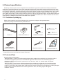
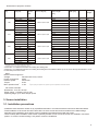
Electric projection screen
Avers Stratus 2 Tension
User’s manual
Read these instructions carefully before operating the screen.
Dear Customer,
Thank you very much for the purchase of our product. The manual booklet contains all operation information
you may require to install properly and operate the screen. We hope it will help you to get the most performance and
enjoyment of yournew screen. Enjoytime with the AversScreens product.
SAFETY INFORMATION
NOTICE: Important safety information.
Follow the instructions described in the operating manual for safety reasons. After reading the manual, please store
it in a safe place just in case you need it in the future.
NOTICE: THE DEVICE HAVE TO BE EARTHED.
WARNING:
1) Disconnect the device from the power supply if it will not be used within longer period of time.
2) Do not open the casing of the device in order to avoid possible electric shock. There are not any user operated
parts inside the case of the screen. All service work can be done by Avers Authorized Service Center personnel
only.
3) Do not remove the Ground pin from the power outlet neither connect the device to the socket without the Ground
pin. If you can't put the plug to the power outlet, please ask electrician for assistance.
Table of contents:
1. Safety rules
1.1. Declaration of Conformity CE
2. Product specification
2.1. Contents of package
2.2. Technical data
3. Screen installation
3.1. Installation directions
3.2. Ceiling installation
3.3. Wall installation
3.4. Electric installation
3.5. Screen programming
3.6. +DELTA wireless remote control
system programming
4. Screen operation
4.1 Manual operation
4.2 Screen maintenance
4.3 Before asking for service
5. Warranty conditions
2
1. SAFETY RULES
SAFETY INFORMATION
NOTICE: Important safety information. It is important for the safety of persons to follow these instructions.
After reading the manual, please save it just in case of need in the future
?
Do not allow children to play with the fixed controls (remote control).
?
Keep the remote control unit out of reach of children.
?
Frequently examine the screen installation for imbalance and signs of wear or damage to cables. Do not use if repair or
adjustment is necessary.
?
Watch the moving screen and keep the people away until the screen is completely rolled in/out. It will help to avoid
injuries caused with moving screen.
?
Do not attach any objects to the screen’s bottom bar. Screen damage and/or person injury danger.
?
All installation work should be carried out by the qualified technician.
?
Improper installation of the screen can cause device damage or health breakdown.
?
Ceiling/wall installation can be done with the originally supplied mounting brackets dedicated for this model only.
?
Do not do anything that may damage the power cable or power plug.
?
Do not damage the power cable: make any modifications by your own, put it near the hot objects, bend it strongly,
twist it, pull out the power cable, put the heavy objects on the cable, wrap it into the bundle.
?
Operation of the screen with damaged power cord can result with electric shock, electric short circuit and fire.
?
Do not touch the power cable and the power plug with wet hands.
?
Always follow the instructions described in the operating manual.
1.1. Declaration of Conformity CE
Manufacturer’s Declaration of ConformityCE
AVERS Screens Sp. z o.o.
Under it’s own responsibility declares:
All screensand accessories mentioned below are manufactured in Polandaccording to the essential safety
requirements of Council Directive 98/79/WE
Projection screens: Stratus 2, Stratus, Focus, Cumulus X, Solar, Solaris, Contour, Altus,
Cirrus CL, Cirrus X, Cirrus X Crank
Projector mount brackets: Alumount, Promount, SimpleMount, ShortMount, Prolift
The above mentioned products are in conformity with the European Directives
and especially with the norms:
PN-EN 55014-1:2007(U)
PN-EN 50082-1:1997
PN-EN 60335-1:2004
PN-EN 61000-3-2:2007
PN-EN 61000-3-3:1997
IEC 60335-2-97:2007
3
2. Product specification
Electrically rolled projection screen designed for fixed installation at projection systems for business presentations
and/or home cinema applications. Screen case made with aluminium alloy, decorative elements at the screen main body
available optionally in many colors but white is a standard. Dustproof bottom door secure projection fabrics ofrolled screen
from polutions. Bottom door operate automatically during screen operation. Screen can be installed at wall or at the ceiling
as a standard. Optional dedicated inceiling installation kit allows hidden installation of Stratus 2 screen in the recessed
ceiling. Best picture quality can be reached when the selection of the type of projection surface and size will be optimal for
the, projection device (projector) and projection conditions at the planed installation place. Built-in wireless remote control
system (factory installable option) allows comfortable screen operation.
2.1. Contents of packaging
Please, check carefully if any physical damage of the screen has not happen during transportation.
Inspect the package for all accessories presented below:
x2
x2
x2
Screen x 1
Wall control switch x 1*)
Radio Frequency
remote transmitter**) x 1
*)
**)
Installation brackets
Regulation wrench x 1
M6x20 x 2
Installation accessories
Operation manual x 1
standard equipment for the screens without built-in control system
standard equipment for the screens with built-in +DELTA control system
2.2 Technical Data
Projection fabrics characteristics:
- Matt White (MW) – a special screen dedicated polyester fabric double side covered with vinyl, black back surface
and white front (projection) surface, recommended for application with DLP and LCD multimedia projectors.
Neutral color of the surface enables projection from any directions. Gain: 1.0, viewing angle: 150 degrees,
thickness: 0,35 mm.
- Matt Grey (MG) – a special screen dedicated polyester fabric double side covered with vinyl, black back surface
and grey front (projection) surface, recommended for application with high brightness DLP and LCD multimedia
projectors. The surface offers deeper level of black and more realistic rich dark colors recognized as a feeling of higher
image contrast. Recommended for home cinema applications. Gain: 0,8. viewing angle: 150 degrees,
thickness: 0,35 mm.
4
Dimensions of projection screens.
Screen width Viewing area
size [cm]
[cm]
180
210
240
270
*)
**)
180 x 101,2
180 x 112,5
180 x 135
180 x 101,2
180 x 112,5
180 x 135
210 x 118,2
210 x 131,3
210 x 157,5
210 x 118,2
210 x 131,3
210 x 157,5
240 x 135
240 x 150
240 x 180
240 x 135
240 x 150
240 x 180
270 x 151,9
270 x 168,8
270 x 151,9
270 x 168,8
270 x 202,5
Screen
aspect
ratio
Screen case size
W x H x D [cm]
16:9
16:10
4:3
16:9
16:10
4:3
16:9
16:10
4:3
16:9
16:10
4:3
16:9
16:10
4:3
16:9
16:10
4:3
16:9
16:10
16:9
16:10
4:3
222 x 12,3 x 12,8
257 x 12,3 x 12,8
285 x 12,3 x 12,8
319 x 12,3 x 12,8
Projection fabrics
max. length
[cm]
Top belt
width [cm]
Version
141,2
152,5
175
111,2
122,5
145
148,2
171,3
197,5
128,2
141,3
167,5
175
195
195
145
160
190
191,9
208,8,5
161,9
178,8
212,5
40
40
40
5
5
5
40
40
40
5
5
5
40
40
10
5
5
5
40
40
5
5
5
BT
BT
BT
BB
BB
BB
BT
BT
BT
BB
BB
BB
BT
BT
BT
BB
BB
BB
BT
BT
BB
BB
BB
*)
Net
**)
weigth
9,8
9,9
10,0
9,5
9,7
9,8
11,6
11,8
12,0
11,3
11,5
11,7
14,0
14,1
14,4
13,5
13,7
13,9
15,7
16,0
15,0
15,3
15,6
BT and BB versions are available with MW, MG or WI fabrics
approximate value for the screen with Matt White fabrics
Version BB – 5 cm width black border surrounding the viewing area
Version BT – 5 cm width black border surrounding the viewing area and additional black top 40 cm above the top black border or 10cm
for 240x180 picture size screen.
Motor:
Electric tubular engine AC:
220-240V AC 50 Hz, 125 W
Voltage:
0,52A
Power consumption:
28 obr./min
Rotation speed:
6 Nm
Torque:
*)
Max. operation time : 4 min
Engine single cycle operation time, operation cycle can be repeated in 20 minutes intervals.
*)
RF remote controller:
Dimensions: 110 x 58 x 20 mm
Power supply: 1 x battery 12V typ 23A
Operating range: up to 100m at open space
3. Screen installation
3.1. Installation precautions
- Installation work should be carried out by a qualified technician in accordance with the instructions described below.
- Fixed installation of the screen should be done with use of the screws and anchors suitable for the walls/ceilings
materials at the installation place and the genuine installation brackets delivered with the screen.
- Check carefully after installation if the screen is perfectly leveled. Do not roll out the screen not installed in horizontal
position. In case the screen leveling is not perfect correct the installation.
5
3.2. Ceiling installation
- Appoint the location of the ceiling mount brackets fixing points.
- Drill holes for anchors fixing the screen brackets to the ceiling.
- Fix the ceiling brackets with anchors (see picture 1).
The mounting anchors diameter should be not smaller than Ø8 mm. In case of the cartboard-plaster ceiling installation,
use cartboard-plaster dedicated Ø11mm diameter steel anchors with screws.
- Slide screen fixing bolts into the casette chanels (see Picture 2).
- Twist the screen casette and slide the chanel onto the ceiling brackets front hinge (see Picture 3).
- Twist the screen casette back to the horizontal position (see Picture 4)
- Slide locking bolts to the lock position (see Picture 4).
m
m
0
0
1
.
n
mi
D = (3/4W+55)±W/6
W - screen width in milimeters
Picture 1 Fixing screen ceiling brackets
Picture 2 Screen ceiling installation - phase 1
Picture 3 Screen ceiling installation - phase 2
Picture 4 Screen ceiling installation - phase 3
Check the screen case leveling before first unrolling the screen.
Do not use the screen if it is not properly installed (leveled).
3.3. Wall installation
- Appoint the location of the ceiling mount brackets fixing points.
- Drill holes for anchors fixing the screen brackets to the ceiling.
- Fix the screen wall brackets to the wall with anchors (see Picture 5).
6
40
The mounting screws diameter should be not smaller than Ø8 mm. In case of the cartboard-plaster walls
installation, use cartboard-plaster dedicated steel anchors with Ø11mm diameter screws.
D = (3/4W+55)±W/6
W - screen width in milimeters
Picture 5 Fixing screen wall brackets
Picture 6 Screen wall installation - phase 1
Picture 7 Screen wall installation - phase 2
Picture 8 Screen wall installation - phase 3
- Fix the ceiling brackets and the wall brackets with the screws supplied with the screen.
- Slide screen fixing bolts into the casette chanels (see Picture 6).
- Twist the screen casette and slide the chanel onto the ceiling brackets front hinge (see Picture 7).
- Twist the screen casette back to the horizontal position (see Picture 8).
- Slide locking bolts to the lock position (see Picture 8).
Check the screen case leveling before first unrolling the screen.
Do not use the screen if it is not properly installed (leveled).
3.4. Electric installation
- Lead out the power cables to:
a) the place of screen installation (screens with built-in remote control system),
b) the place of installation of the wall switch and between wall switch and screen (screenss without built--in control
systems).
- Screen power line should be fused with 1A fuse.
- Switch off the screen power line during installation work.
- Manual wall steering switch should be installed at the place meeting the following conditions:
a) installation150-180 cm above the floor level,
b) the screen should be visible by the wall switch operator during the screen operation,
c) wall switch operator cannot stay in reach of any of the screen’s moving parts during the screen operation .
d) the wall switch must be visible from the each part of the room irrespective of the screen position.
7
ATTENTION: Electric installation work should be carried out by a certified electrician.
yg
bl
br
~
bk
Screen
bl - blue (common)
br - brown (rolling up)
yg - yellow-green (protective)
bk - black (rolling down)
bl br yg
~
Power line
L1 - brown (live)
N - blue (neutral)
G - yellow-green (protective)
Picture 9 Screen without remote control system
electric installation
Screen
bl - blue (common)
br - brown (live)
yg - yellow-green (protective)
Power line
L1 - brown (live)
N - blue (neutral)
G - yellow-green (protective)
Picture 10 Screen with built-in +DELTA control
system electric installation
Picture 12 Lower bar fine tuning
3.5. Screen programming
!!! NOTICE !!! The screen was programmed properly at the factory and there is no need to reprogram it without any
important reason. Setting of screen extreme positions was made by manufacturer.
If you need to change the screen extreme position follow the instructions described below.
Changes of the screen height can result in screen surface flatnes deterioration (waves could appear).
Programing the length of the rolled out screen (screen bottom bar position).
- Roll up the screen until it will stop automatically in the upper position.
- Insert regulation wrench included in the screen set into the regulation slot (see picture. 6) located in the left bottom
part of the screen .
Regulation knob “1” (located closer to the front of the screen) enables setting of the lower extreme position of the
screen bottom bar:
„+” - means increasing the lenght of the fabrics is rolled down when the screen is rolled out,
„–” - means decreasing the length of the fabrics is rolled down when the screen is rolled out.
8
Regulation knob “2” (located closer to the back of the screen) enables setting of the upper extreme position of the
screen bottom bar:
“-“ - means increasing the lenght of the fabrics is rolled down when the screen is rolled in,
“+” - means decreasing the length of the fabrics is rolled down when the screen is rolled in.
!!! IMPORTANT !!!
Do not decrease (tuning knob 1+) the range of the rolled down surface. It can damage the screen.
Do not increase (regulation 2+) the range of the surface which was rolled down behind the STOP mark, placed in
the upper right corner of the screen. Rolling down the screen behind the mark can damage the screen.
Tensioning wires were setup during screen manufacturing optimally. It would be necessary to modify the power of
the tensioning wires after few years of screen use. Finetuning could be performed with 2mm hexagonal wrench applied
into the regulation holes located at bottom bar end caps. Deterioration of projection surface flatness wil be affected as a
result of improper finetuning of tensioning wires. Waves at the projection surface will cause problems with picture
quality in case of geometry and sharpness.
Pic.12 Tensioning wire regulation screws location
3.6. +DELTA remote control system programing
Parallel operation of a few screens with built-in +DELTA installed in the same room is possible; in such case control
systems of each screen must be programmed with dedicated control code. The screen with +DELTA remote control
system is supplied with single remote transmitter, it is possible to purchase optional transmitters. The optional transmitters
must be programmed at the controller.
A) Setting of the new transmitter
Controller can memorize 10 individual control codes of remote transmitters.
?
Connect power supply to the screen.
?
Press 3 times P2 button of the remote transmitter within 12 seconds after the screen’s sound signal.
?
Transmitter is not set to the control system with individual code (random generated code).
B) Deleting of the transmitter
?
Connect power supply to the screen.
?
Press P2 button of the remote transmitter once.
?
Press the “Stop” button of the remote transmitter within the next 4 seconds.
?
Press P2 button within the next 4 seconds again.
?
The remote transmitter was deleted from the controller memory.
C) Appending additional remote transmitter
Appending new transmitter procedure has 2 steps. First step the remote transmitter supplied with the screen must be
set as the main remote transmiiter, in second step the optional new transmitter can be set up to operate with the
screen.It is possible to append multiple transmitters to the screen with the procedure described below.
?
Connect power supply to the screen.
?
Press P2 button of the original remote transmitter twice, the screen will generate sound.
?
Press “•
” button of the new remote transmitter once within the next 4 seconds.
?
Setting up of the main remote transmitter will be confirmed with the sound signal.
?
We recommend to mark the main remote transmitter to identify it easily in the future.
?
Press P2 button of the main remote transmitter twice, the screen will generate sound.
?
Press P2 button of the new remote transmitter once within the next 4 seconds.
?
Appending of the new remote transmitter will be confirmed with sound.
9
4. Screen operation
Projection screen AVERS can be operated manually or automatically with optional control systems Avers ALFA-Trigger,
ALFA-wireless trigger or Beta.
!! CAUTION !!
Roll out the screen a few minutes before projection will start.
The screen should be rolled in after projection is finished.
Projection surface would be damaged if the screen would be left open for a longer period of time.
4.1 Manual operation
Manual screen operation is possible with the wall control switch or by radio frequency transmitter of the optional remote
control system.
- Push button „‚
”, the screen will begin to roll down and stop automatically at the bottom position after rolling down.
- Push “Stop” button of the remote transmitter, screen rolling operation will be stopped.
- Push button „•
”, the screen will begin to roll up and stop automatically in the upper position after rolling up.
4.3. Screen maintenence
Pojection screen Avers do not require periodical service maintenance. Clean dust from the screen case and fabrics with
dry soft cloths. If needed use moisturized cloth with soft detergent to remove stains. After stain removal dry the cleaned
surface with cloth carefully.
4.3. Before calling the service
Symptoms
Reasons
Remedy
The screen fabrics does not
roll down
Power failure
Check the screen’s circuit fuse and the
power cable
The screen fabrics does not
roll down/up automatically
Projector power cord plug is not connected
to the trigger transmitter outlet.
Connect projector power cord plug to the
trigger transmitter outlet
The screen fabrics does not
roll down smoothly
The screen was not installed properly in
horizontal position.
Check if the screen case is properly leveled.
Reinstall the screen correctly.
The screen stops in the
middle position.
There are some objects on the bottom bar
way.
Remove the objects which can block the
proper work of the screen or are at the
bottom bar way.
Power failure
Check the propriety of electric installation
and the state of the power wires.
At other cases please contact service.
5. Warranty conditions
1) Avers screens warranty period is 24 months from the date of purchase confirmed with the original purchase invoice.
2) Extended warranty period for electric engine is 60 month.
3) Surety commits to fix free of charge any failures (component or production defects) of the product which appear during
warranty period.
4) Warranty exclusions :
a) the failures caused by the usage of the screen against the rules described in operation manual,
b) the failures caused by improper storage or transportation,
c) mechanical defects of the screen other than mentioned at point 3),
d) damages caused with overvoltage at power network,
e) deinstallation and reinstallation of the screen.
5) Avers Screens Service department will remove all defects within 21 days after receiving the demaged product.
6) Warranty claims should be passed to the screen supplier (dealer).
10
Manufactured after 13.08.2005
This symbol on the products and/or accompanying documents means that used electrical and
electronic products should not be mixed with general household waste. Disposing of this
product correctly will help to save valuable resources and prevent any potentialnegative effects
on human health and the environment which could otherwise arise from inappropriate waste
handling. Please contact your local authority for further details of your nearest designated
Wersja
collection point.
15.01.2015