1
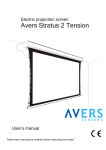
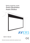
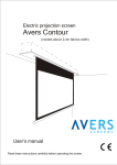
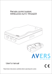
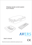
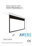
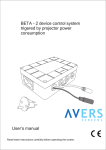
Radio triggered control system C12VRC User’s manual Read these instructions carefully before operating the screen. Dear Customer, Thank you very much for the purchase of our product. The manual booklet contains all operation information you may require to install properly and operate the radio remote control system. We hope it will help you to get the most enjoyment of your new control system. Enjoy time with the Avers Screens product. SAFETY INFORMATION NOTICE: Important safety information. Follow the instructions described in the operating manual for safety reasons. After reading the manual, please store it in a safe place just in case you need it in the future. NOTICE: THE DEVICE HAVE TO BE EARTHED. WARNING: 1) Disconnect the device from the power supply if it will not be used within longer period of time. 2) Do not open the casing of the device in order to avoid possible electric shock. There are not any user operated parts inside the case of the screen. All service work can be done by Avers Authorized Service Center personnel only. Table of contents: 1. Safety rules 1.1. Declaration of Conformity CE 2. Product specification 2.1. Contents of package 2.2. Technical data 3. Control system installation 3.1 Installation directions 3.2 Control unit installation 3.3 Electric installation 3.4 Control system programming 4. Control system operation 4.1 Automatic operation 4.1 Manual operation 4.2 Control system maintenance 4.3 Before asking for service 5. Warranty conditions 1. SAFETY RULES SAFETY INFORMATION NOTICE: Important safety information. It is important for the safety of persons to follow these instructions. After reading the manual, please save it just in case of need in the future. Do not allow children to play with the remote control transmitter or fixed manual switch connected to the control system. Keep the remote control transmitter out of reach of children. 2 Frequently examine the control system installation for imbalance and signs of wear or damage to cables. Do not use if repair or adjustment is necessary. Watch the moving screen and keep the people away until the screen is completely rolled in/out. It will help to avoid injuries caused with moving screen. All installation work should be carried out by the qualified technician. Improper installation can cause device damage or health breakdown. Do not do anything that may damage the power cables. Operation of the control system with damaged power cords can result with electric shock, electric short circuit and fire. Do not touch the power cables and the control unit with wet hands. Do not allow nor Control Unit nor Trigger Transmitter to flood with water, it can result with electric shock, electric short circuit and fire. Do not apply any metallic objects into the Trigger Transmitter though the venting holes, it can result with electric shock, electric short circuit and control system damage. Always follow the instructions described in the operating manual. 1.1 Declaration of Conformity CE Manufacturer’s Declaration of ConformityCE AVERS Screens Sp. z o.o. Under it’s own responsibility declares: All screensand accessories mentioned below are manufactured in Polandaccording to the essential safety requirements of Council Directive 98/79/WE Control systems: DRC-2, CRC-2, CRC-IR, C12VRC, The above mentioned products are in conformity with the European Directives and especially with the norms: PN-EN 55014-1:2007(U) PN-EN 50082-1:1997 PN-EN 60335-1:2004 PN-EN 61000-3-2:2007 PN-EN 61000-3-3:1997 IEC 60335-2-97:2007 2. Product specification Radio triggered control system C12VRC is dedicated for automatic remote control of electric projection screens by Avers Screens, electric projector lifts Avers ProLift and other home electric appliances (electric curtains, etc). The control system was designed for fixed installation at projection systems for business presentations and/or home cinema applications. Trigger transmitter senses the increased power consumption of the projector attached to the integrated outlet. When the projector lamp is on, control signal is generated. Control signal is transmitted to the Control Unit with RF connection. In case of the Trigger Transmitter failure manual operation with connected wall switch is possible. The Control Unit can be used in slave mode as controller with external control systems (intelligent building installations). Single Trigger Transmitter can drive multiple Control Units if all devices are set with the same control code. Control Systems with different control codes can operate in the same area without interfere. 3 2.1 Contents of packaging Please, check carefully if any physical damage of the control system has not happen during transportation. Inspect the package for all accessories presented below: Operation manual x 1 Trigger transmitter x 1 Control unit x 1 2.2 Technical Data Control Unit: Dimensions: 78 x 128 x 45 mm Supply voltage: 220-240V, AC 50Hz Control votage: 220-240V, AC 50Hz Max. control current: 1,5A Control Unit activity period: 90s Front view Trigger Transmitter: Dimensions: 90 x 58 x 65 mm Supply voltage: 220-240V, AC 50Hz Max. power consumption: 600W Operation range: up to 25m (environment conditions dependend) Radio wave frequency: 433MHz Rear view Front view Rear view OUTPUT: AC 230V 350W max. FOR INTERNAL USE ONLY Serial No. Code Model H-61 INPUT: AC 230V 50/60 Hz 1,5 Watt Serial No. 5 Model C12VRC Transmitter 433MHz Input AC 230 V Output max. 230V 600W 2 Code 5 3 4 1 - Power plug cable 2 - Control code information 3 - Projector outlet cable 4 - Power consumption indicator Picture 1 Control Unit 1 Picture 2 Trigger Transmitter 3. Control system installation 3.1. Installation precautions - Installation work should be carried out by a qualified technician in accordance with the instructions described below. - Fixed installation of the control system should be done with use of the screws and anchors suitable for the walls/ceilings materials at the installation place and the genuine installation brackets delivered with the screen. 3.2. Control unit installation - Appoint the location of the control unit fixing points (see Appendix). - Drill holes for the fixing anchors. - Un tight 2 plastic screws and remove the front cover of Control Unit. - Fix the control unit with anchors. 4 3.3 Electric installation - Lead out the power cables to the place of Control Unit installation. - Control Unit power line should be fused with 3,15A fuse. - Switch off the screen power line during installation work. - Manual wall steering switch should be installed at the place meeting the following conditions: a) installation150-180cm above the floor level, b) the screen should be visible by the wall switch operator during the screen operation, c) wall switch operator cannot stay in reach of any of the screen’s moving parts during the screen operation. - Connect screen cable to the control terminal as shown at the Picture 3. - Optionally connect external control system or manual wall switch to the manual control terminal as shown at the Picture 3. - Connect power supply cable to the power supply terminal as shown at the Picture 3. - Apply front cover of and fix it with plastic screws. - Apply projector power cord wall plug to the power outlet located at the trigger signal transmitter - Connect Trigger Transmitter to the wall outlet you plan to connect projector power cord. ATTENTION: Electric installation work should be carried out by a certified electrician. 2 5 Screen/Lift 1 bk br bl yg 1 - Activity Indicator 2 - Control Terminal 3 - Power Supply Terminal 4 - Manual Control Terminal 5 - Cables Inlet ~ Optional manual control Control unit PCB 3 4 Inside view (front cover removed) Picture 3 C12VRC Control Unit electric installation !!! NOTICE !!! Screen/Lift cable bl - blue (common) br - brown (rolling up) yg - yellow-green (protective) bk - black (rolling down) Power cable L1 - brown (live) N - blue (neutral) G - yellow-green (protective) Do not connect any any electric devices except multimedia projector to the power outlet located at the Trigger Transmitter. Maximum projector power consumption 600W. 3.4 Control system programming Each C12VRC has factory programmed individual control code. The Control code number is indicated at the Control Unit body and the Trigger Transmitter body see pictures 1 and 2. Only the Control Unit and Trigger Transmitter with matching control codes will work together. Single Trigger Transmitter can control multiple Control Units with matching code number. Parallel independent operation of multiple C12VRC control systems in the same area requires each system to have programmed different control code. It is possible to change the control code in case it is really required. You will need the following tools: screw driver, projection screen or lift, optional wall switch and multimedia projector or other electric device with power consumption of 150W or more. Programming procedur must be performed in 2 steps. Step 1 - Remote Transmitter programming procedure: - Detatch transmitter from power supply (wall outlet) and projector. - Remove 4 screws located at the back side of the transmitter with screwdriver. - Pick up the transmitter front cover. - Change the control code with the program switch. (see Picture 4). - Put the transmitter front cover back to it’s place. - Secure the enclosure with 4 screws. - The control code was programmed, the unit is ready for operation. 5 !!! CAUTION !!! Some components inside the transmitter and control unit enclosures are under 230V voltage. We recommend to ask qualified electrician to program the control unit and transmitter. Keep highest attention when programming devices to avoid electic shock. Inside view (front cover removed) 1 5 Transmitter PCB ON Code 2 1 2 3 4 5 1 - Power plug cable 2 - Activity indicator 3 - Antenna 4 - Programming switch 5 - Projector outlet cable ON Code 3 1 2 3 4 5 ON 1 2 3 4 5 4 ON Code 4 1 2 3 4 5 ON Code 5 1 2 3 4 5 3 2 Picture. 4 Transmitter programming (factory configured code settings) Step 2 - Control Unit programming procedure Connect screen, optional wall switch and power supply to the Control unit (see picture 3). Connect the remote transmitter to the wall outlet. Plug in the projector wall plug into the power outlet of the rempote transmitter (the projector lamp must be off). Set the wall switch at the “ ” position and keep it at the position for about 1 minute (the screen motor could operate or not if the screen is rolled-in completely). The screen fabrics will roll out partially and stop to confirm the control unit is ready to programm the new code. Power on the projector (the lamp must light) connected to the remote transmitter, the transmitter control light will light to confirm the control code is transmitted. The screen will start to roll out the fabrics, control unit will generate the sound signal confirming the code was accepted. Power off the projector (the lamp must stop lighting, the fans of projector cooling system can operate), transmitter will send the signal to roll in the screen fabrics. As soon as the screen fabrics is rolled in completely the code programming procedure is finished successfully. In order to restore to the screen the original (factory set) control code, you must perform the programming procedure with transmitter set to the original factory code. 4. Control system operation C12VRC radio triggered control system allows automatic and manual control of Avers electric projection screens (models without integrated control system only), and Prolift electric projector lifts. Both operation methods can be used simultaneously if optional wall switch is installed. 4.1 Automatic operation Automatic screen operation is provided with use of the triggered signal radio frequency transmitter. - Press “POWER” button at the projector’s remote control transmitter or at the projector itself, projector lamp will light on. Trigger Transmitter will sound the signal, activity indicator will turn red, the screen/lift engine will begin operation and it will stop automatically when bottom position of screen/lift will be reached. - Press “POWER” button at the projector’s remote control transmitter or at the projector itself, projector lamp will light off, Trigger Transmitter will sound the signal, activity indicator will turn off, the screen/lift engine will begin operation and it will stop automatically when upper position of screen/lift will be reached. 4.2 Manual operation Manual screen operation is possible with the optional wall control switch (original screen/lift wall control switch). - Push button „€ ”, the Control Unit will sound the signal, “DOWN” activity indicator will turn on, the screen/lift engine will begin operation and it will stop automatically when bottom position of the screen/lift will be reached. - Push button „ ”, the Control Unit will sound the signal, “UP” activity indicator will turn on, the screen/lift engine will begin operation and it will stop automatically when upper position of the screen/lift will be reached. 6 = 4.2 Control system maintenance C12VRC control system do not require periodical service maintenance. Clean dust from the control unit and trigger transmitter cases with dry soft cloths. If needed use moisturized cloth with soft detergent to remove stains. After stain removal dry the cleaned surface with cloth carefully. 4.3 Before calling the service Symptoms Reasons Remedy Screen/lift operates itself Trigger signal was send from another trigger transmitter installed somewhere in the neigborhood. Replace the control system with a new with different control code. Control system do not react to Projector power cord is not plugged into the Plug in projector power cable to the Trigger projector “Power On” action Trigger Transmitter outlet. Transmitter outlet. Power consumption from the outlet at the Trigger Transmitter is too low. Use projector with higher power consumption. At other cases please contact service. 5. Warranty conditions 1) Avers control system warranty period is 24 months from the date of purchase confirmed with the original purchase invoice. 3) Surety commits to fix free of charge any failures (component or production defects) of the product which appear during warranty period. 4) Warranty exclusions : a) the failures caused by the usage of the control system against the rules described in operation manual, b) the failures caused by improper storage or transportation, c) mechanical defects of the control system other than mentioned at point 3), d) damages caused with overvoltage at power network, e) deinstallation and reinstallation of the screen. 5) Avers Screens Service department will remove all defects within 21 days after receiving the demaged product. 6) Warranty claims should be passed to the screen supplier (dealer). Appendix Control unit installation template - Apply the template at the place you intend to install the Control Unit and appoint the centers of holes for the fixing anchors - Drill the holes in appointed places. 7 119 !!! CAUTION !!! Check the holes printed at the template match the location of fixing points at the control unit before you use it. 65 Manufactured after 13.08.2005 This symbol on the products and/or accompanying documents means that used electrical and electronic products should not be mixed with general household waste. Disposing of this product correctly will help to save valuable resources and prevent any potentialnegative effects on human health and the environment which could otherwise arise from inappropriate waste handling. Please contact your local authority for further details of your nearest designated collection point.