1
Frequently Asked Questions
BCM110X/BCM111X/BCM119X
PhonexChange™ 3.6 FAQ
110X_111X_119X-FAQ104-R
5300 California Avenue • P.O. Box 57013 • Irvine, California 92617 • Phone: 949-926-5000 • Fax: 949-926-5203
10/15/08
REVISION HISTORY
Revision
Date
Change Description
110X_111X_119X-FAQ104-R
10/15/08
Updated:
• Section 1: “Introduction”
• Section 2: Frequently Asked Questions:
• Ethernet, “Using the Switch as a Router” on page 32
• File System, “Supported Devices” on page 36
• Peripherals, “Watchdog Timer” on page 53
• Appendix A, “Glossary and Acronyms”, on page 91
110X_111X_119X-FAQ103-R
06/10/08
Updated:
•
•
•
•
•
•
•
•
•
•
•
•
•
•
•
•
•
•
Version information throughout the document
“References” on page 1
“BCM1101 Family” on page 3
“BCM1190 Family” on page 5
“Broadcom Customer Support Portal Product Cases” on page 6
“Build Environment” on page 9
“Endpoint” on page 14
“Ethernet” on page 30
“File System” on page 36
“H.323 Call Control” on page 38
“Peripherals” on page 47
“Protocol” on page 64
“Enabling IGMP” on page 65
“Tools” on page 70
“Security” on page 82
“SIP Call Control” on page 84
“Broadcom Profiling Tools” on page 80
“DNS SRV Queries” on page 85
Broadcom Corporation
P.O. Box 57013
5300 California Avenue
Irvine, California 92617
© 2008 by Broadcom Corporation
All rights reserved
Printed in the U.S.A.
Broadcom ®, the pulse logo, Connecting everything ® , the Connecting everything logo, PhonexChange™, and
HausWare® are among the trademarks of Broadcom Corporation and/or its affiliates in the United States, certain other
countries and/or the EU. Any other trademarks or trade names mentioned are the property of their respective owners.
Frequently Asked Questions
BCM110X/BCM111X/BCM119X
10/15/08
Revision
Date
Change Description
110X_111X_119X-FAQ102-R
10/18/07
Updated:
• “Building a Newly Added Library (Folder)” on page 10
• “Controlling Behavior of Adaptive Jitter Buffer” on page 13
• “Adaptive Jitter Buffer Statistics” on page 14
• “Increasing the Size of NOR Flash” on page 38
Added:
• “SRTP” on page 21
110X_111X_119X-FAQ101-R
110X_111X_119X-FAQ101-R
(continued)
4/11/07
4/11/07
Added:
• “Platform CD 3.3 Installation” on page 10
• “JTAG Tool Cannot Communicate With Device” on page 72
Updated:
• “Cover Title” on page i
• PhonexChange version from 3.3 to 3.4
• “References” on page 1
• “Build Aborted for No Apparent Reason” on page 10
• “Creating a New Platform Profile Procedure” on page 10
• “Building a Newly Added Library (Folder)” on page 12
• “Wind River PCD3.3 Compatibility” on page 13
• “Supporting Port Mirroring” on page 33
• “Adding NOR Memory Device Types” on page 36
• “Convert a Platform from NAND flash to NOR flash” on page 37
• “Modifying RAM Memory Mapping” on page 38
• “Modifying Flash Memory Mapping” on page 38
• “Changing Flash Size” on page 39
• “Changing SDRAM Size” on page 42
• “Using Different Flash and SDRAM Chips” on page 42
• “Network Cluster Pool” on page 43
• “Adding Serial Ports” on page 46
• “Testing the USB” on page 56
• “LCD Attributes” on page 57
• “Keyboard Mapping” on page 58
• “External LEDs” on page 60
• “Enabling IGMP” on page 63
• “udpSend Errors” on page 63
• “Soft Resets” on page 67
• “PhonexChange 2.x Boot Image” on page 68
• “Using the Workbench Debugger Through the Network
Interface” on page 74
Bro adco m Co rp or atio n
Document
110X_111X_119X-FAQ104-R
Page iii
BCM110X/BCM111X/BCM119X
Frequently Asked Questions
10/15/08
Revision
Date
Change Description
110X_111X_119X-FAQ104-R
10/15/08
• “Using the Workbench Debugger Through the Serial
Interface” on page 75“Wind River System Viewer Application
Support” on page 78 (formerly Windview Application Support)
• “802.1x in PhonexChange” on page 80
• “OpenSSL Source Files” on page 81
• “SDP Formation” on page 82
• “SIP and IP Destination Addresses” on page 84
• “Registration” on page 85
• “Setting WAN IP Address” on page 85
• “Unsubscribing” on page 86
• “Vocoder Negotiation” on page 87
Removed:
110X_111X_119X-FAQ100-R
09/12/06
• “Reference Design Summary” on page 8
• “Build Environment” on page 13
• “Inability to Link to PhonexChange Build Environment using
PCD2.0” on page 14
• “Building PhonexChange Using Toronado IDE” on page 19
• Failed Booting of Chip on page 91
Initial release
Bro adco m C orp or atio n
Page iv
Document
110X_111X_119X-FAQ104-R
Frequently Asked Questions
BCM110X/BCM111X/BCM119X
10/15/08
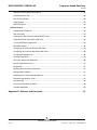
TABLE OF CONTENTS
Section 1: Introduction........................................................................................................ 1
References .................................................................................................................................................... 1
Section 2: Frequently Asked Questions ............................................................................ 2
APPTEST....................................................................................................................................................... 2
Key Features........................................................................................................................................... 2
Commands and Call Connections .......................................................................................................... 2
BCM1101 Family........................................................................................................................................... 3
BCM1101 Family Feature Differences .................................................................................................... 3
BDSL File for the BCM1113 and BCM1115............................................................................................ 3
BCM1103 Family........................................................................................................................................... 4
BCM1103 Family Feature Differences .................................................................................................... 4
BDSL Files for the BCM91104xx Platforms ............................................................................................ 4
BCM1103/1104 MIPS Core .................................................................................................................... 4
BCM1190 Family........................................................................................................................................... 5
BCM1190 Family Features ..................................................................................................................... 5
BCM1190 MIPS Core ............................................................................................................................. 5
Broadcom Customer Support Portal Product Cases................................................................................ 6
Product Case Notification ....................................................................................................................... 6
Downloading Cases ................................................................................................................................ 6
Sending Questions to Support Engineers ............................................................................................... 6
Can Proprietary Information Be Posted on the Web Interface? .............................................................. 8
Can E-mail Generated by Product Cases be Replied to Directly?.......................................................... 8
What Happens When Replied-to e-mail is not Received by the System? .............................................. 8
BSP ................................................................................................................................................................ 8
Changing the End Device Name............................................................................................................. 8
Build Environment ....................................................................................................................................... 9
Platform CD 3.6 Installation .................................................................................................................... 9
Clean Builds ............................................................................................................................................ 9
Build Aborted for No Apparent Reason................................................................................................... 9
Creating a New Platform Profile.............................................................................................................. 9
Creating a New Platform Profile Procedure ............................................................................................ 9
Building a Newly Added File ................................................................................................................. 10
Bro adco m Co rp or atio n
Document
110X_111X_119X-FAQ104-R
Page v
BCM110X/BCM111X/BCM119X
Frequently Asked Questions
10/15/08
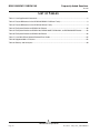
Building a Newly Added Library (Folder) ...............................................................................................12
Wind River PCD3.6 Compatibility..........................................................................................................13
Makefile Format.....................................................................................................................................13
Adding Custom Defines to Makefile ......................................................................................................13
Endpoint ......................................................................................................................................................14
Adaptive Jitter Buffer .............................................................................................................................14
Jitter Buffer Recommended Settings.....................................................................................................14
Controlling Behavior of Adaptive Jitter Buffer........................................................................................14
Adaptive Jitter Buffer Statistics..............................................................................................................15
Adaptive Jitter Buffer Statistics Interval .................................................................................................15
RTP Statistics and Jitter Reports...........................................................................................................15
Accessing the IOM2 Audio Channel......................................................................................................15
Broadcom ECAN Tail Length ................................................................................................................15
Default PLC Mode .................................................................................................................................16
VAD Values ...........................................................................................................................................16
Equalization Filter ..................................................................................................................................16
High-pass Filter .....................................................................................................................................16
Customizing Tones and Rings...............................................................................................................16
Generating Tones and Rings (Ingress) .................................................................................................16
Generating Tones and Rings (Egress) ..................................................................................................17
Generating Tones and Rings (Egress and Ingress) ..............................................................................17
Changing Voice Volume Without Changing Tone Volume ....................................................................17
Restarting Tone Generation ..................................................................................................................17
Attenuating Tone ...................................................................................................................................17
DB Level ................................................................................................................................................17
Generating an RFC2833 DTMF Tone ...................................................................................................18
Verifying RFC2833 DTMF Tones ..........................................................................................................18
Determining RTP Payload Types ..........................................................................................................18
Interfacing RTP/RTCP Packets From Endpoint to Network ..................................................................19
Changing RTP Ports..............................................................................................................................20
Supported Vocoders..............................................................................................................................20
Troubleshooting Audio Handset ............................................................................................................21
Noise and Saturation .............................................................................................................................21
Resetting RTP Statistics Counters ........................................................................................................21
Units for RTP statistics ..........................................................................................................................21
Bro adco m C orp or atio n
Page vi
Document
110X_111X_119X-FAQ104-R
Frequently Asked Questions
BCM110X/BCM111X/BCM119X
10/15/08
Statistics Incrementing Conditions ........................................................................................................ 21
RTP Statistics Differences .................................................................................................................... 22
SRTP .................................................................................................................................................... 22
Maximum Packetization Values ............................................................................................................ 22
Mapping Endpoint Devices to APM Codecs ......................................................................................... 22
Controlling APM and PGA Gains .......................................................................................................... 23
Sidetone Delay...................................................................................................................................... 23
APM Loopbacks on the BCM1103, 1104, and 1190............................................................................. 24
AEC....................................................................................................................................................... 25
Handset Echo When ECAN Is Enabled ................................................................................................ 28
DSP Assertion....................................................................................................................................... 28
Enabling DSP Features ........................................................................................................................ 29
IP Phone Fails to Generate Tones........................................................................................................ 29
iLBC Audio Codec Support ................................................................................................................... 29
Ethernet....................................................................................................................................................... 30
Denial of Service................................................................................................................................... 30
Detecting Cable Disconnection............................................................................................................. 31
Enabling Loopback Mode ..................................................................................................................... 32
Using the Switch as a Router................................................................................................................ 32
Supporting Port Mirroring ...................................................................................................................... 33
Port Mirroring and 802.1p Priority Retagging........................................................................................ 33
VLAN ID Tags ....................................................................................................................................... 33
802.1p Tags and Incoming Frames ...................................................................................................... 34
Setting Priority Levels ........................................................................................................................... 34
Enabling PHY Interrupts ....................................................................................................................... 35
The L2 Switch and EAPOL Packets ..................................................................................................... 35
Filter Loop Input Ports........................................................................................................................... 35
File System ................................................................................................................................................. 36
Supported Devices................................................................................................................................ 36
File System Device Modification ........................................................................................................... 36
Adding NOR Memory Device Types ..................................................................................................... 37
Adding Flash Memory Device Types .................................................................................................... 37
Convert a Platform from NAND flash to NOR flash............................................................................... 37
H.323 Call Control ...................................................................................................................................... 38
Generating In-Band and Out-of-Band DTMF Tones ............................................................................. 38
Bro adco m Co rp or atio n
Document
110X_111X_119X-FAQ104-R
Page vii
BCM110X/BCM111X/BCM119X
Frequently Asked Questions
10/15/08
Memory ........................................................................................................................................................39
Mapping of Flash and RAM ...................................................................................................................39
Locating the RAM Disk ..........................................................................................................................39
Modifying RAM Memory Mapping .........................................................................................................39
Modifying Flash Memory Mapping.........................................................................................................39
Rebuilding the Boot Image ....................................................................................................................40
Changing Flash Size .............................................................................................................................40
Increasing the Size of NOR Flash .........................................................................................................41
NOR Flash Memory and Addressing.....................................................................................................43
Changing SDRAM Size .........................................................................................................................43
Using Different Flash and SDRAM Chips..............................................................................................44
Reducing Memory Usage ......................................................................................................................44
Network Cluster Pool.............................................................................................................................44
Interfacing to Serial EPROM .................................................................................................................45
NVRAM Location ...................................................................................................................................45
SDRAM Controller and Physical Addresses..........................................................................................45
OS Configuration ........................................................................................................................................46
Increasing the Number of Semaphores.................................................................................................46
Default Task Priorities ...........................................................................................................................46
Peripherals ..................................................................................................................................................47
Changing UART Baud Rates.................................................................................................................47
Enabling and Using UART1...................................................................................................................48
Adding Serial Ports................................................................................................................................48
Using the SPI to Read and Write...........................................................................................................49
Status of the HSS ..................................................................................................................................50
Determining HSS Connections..............................................................................................................50
External Interrupts .................................................................................................................................51
Detecting Chip Revision ........................................................................................................................52
Modifying the Size and Number of BRCM Buffers ................................................................................52
Watchdog Timer ....................................................................................................................................53
Peripheral Timer ....................................................................................................................................54
Testing the USB ....................................................................................................................................59
Serial Port Troubleshooting ...................................................................................................................59
LCD Attributes .......................................................................................................................................60
Keyboard Mapping ................................................................................................................................60
Bro adco m C orp or atio n
Page viii
Document
110X_111X_119X-FAQ104-R
Frequently Asked Questions
BCM110X/BCM111X/BCM119X
10/15/08
Keypad Multi-key Filtering..................................................................................................................... 60
Keyscan Prescale Values ..................................................................................................................... 63
External LEDs ....................................................................................................................................... 63
Peripheral Support on EBI Bus ............................................................................................................. 63
MIPS Virtual Addresses ........................................................................................................................ 63
Protocol....................................................................................................................................................... 64
Dynamic Host Configuration Protocol ................................................................................................... 64
Requesting DHCP Information.............................................................................................................. 64
Enabling DHCP ..................................................................................................................................... 64
DNS PhonexChange Support ............................................................................................................... 64
Enabling IGMP ...................................................................................................................................... 65
udpSend Errors ..................................................................................................................................... 65
TFTP Failure ......................................................................................................................................... 67
UDP Sockets......................................................................................................................................... 67
Resetting and Boot .................................................................................................................................... 68
Boot Sequence of PhonexChange........................................................................................................ 68
Boot Sequence of ZSP Software .......................................................................................................... 68
PC Traffic Disruption ............................................................................................................................. 68
Soft Resets ........................................................................................................................................... 69
Boot Line Flags ..................................................................................................................................... 69
Tools............................................................................................................................................................ 70
PhonexChange 2.x Boot Image ............................................................................................................ 70
Upgrading Boot Code using WRS VisionProbe/VisionICE/VisionClick................................................. 70
Modifying the WRS Register File .......................................................................................................... 70
Upgrading Boot Code using Corelis-ScanICE ...................................................................................... 73
JTAG Tool Cannot Communicate With Device ..................................................................................... 74
Using the Workbench Debugger Through the Network Interface ......................................................... 76
Using the Workbench Debugger Through the Serial Interface ............................................................. 77
VisionClick Debugging .......................................................................................................................... 78
Broadcom Profiling Tools ...................................................................................................................... 80
Wind River System Viewer Application Support ................................................................................... 80
PROTOS SIP Test Suite ....................................................................................................................... 81
Security ....................................................................................................................................................... 82
802.1x in PhonexChange...................................................................................................................... 82
Authentication Methods ........................................................................................................................ 82
Bro adco m Co rp or atio n
Document
110X_111X_119X-FAQ104-R
Page ix
BCM110X/BCM111X/BCM119X
Frequently Asked Questions
10/15/08
Additional Memory Required by 802.1x.................................................................................................83
OpenSSL Source Files ..........................................................................................................................83
EAP-TLS Private Key ............................................................................................................................83
IPSec Support .......................................................................................................................................83
3DES Encryption ...................................................................................................................................83
SIP Call Control...........................................................................................................................................84
Supported RFC Protocols......................................................................................................................84
SDP Formation ......................................................................................................................................84
Generating In-Band and Out-of-Band DTMF Tones..............................................................................84
Generating DTMF Tones During SIP Calls ...........................................................................................84
Turning Off Silence Suppression...........................................................................................................85
DNS SRV Queries .................................................................................................................................85
Configuring SIP Stack for Different UDP Ports......................................................................................86
Configuring SIP Stack for Non-Default UDP Ports ................................................................................ 86
Changing the Register Port ...................................................................................................................86
Initiating Phone Calls.............................................................................................................................86
SIP and IP Destination Addresses ........................................................................................................86
Default Registration Interval ..................................................................................................................87
Registration ...........................................................................................................................................87
Updating SDP Connection Information..................................................................................................87
Setting WAN IP Address .......................................................................................................................87
SIPS Support in PhonexChange Software ............................................................................................87
PhonexChange Session Timer..............................................................................................................87
Unsubscribing........................................................................................................................................88
Parsing and Composing Headers..........................................................................................................88
Vocoder Negotiation ..............................................................................................................................89
Appendix A: Glossary and Acronyms............................................................................. 90
Bro adco m C orp or atio n
Page x
Document
110X_111X_119X-FAQ104-R
Frequently Asked Questions
BCM110X/BCM111X/BCM119X
10/15/08
Bro adco m Co rp or atio n
Document
110X_111X_119X-FAQ104-R
Page xi
BCM110X/BCM111X/BCM119X
Frequently Asked Questions
10/15/08
LIST OF TABLES
Table 1: List of ippConsole Commands ..............................................................................................................2
Table 2: Feature Differences in the BCM110X/BCM111X Silicon Family........................................................... 3
Table 3: Feature Differences in the BCM1103 Silicon Family............................................................................. 4
Table 4: File System Devices on BCM91101 Phones ......................................................................................36
Table 5: File System Devices on BCM91103, BCM91103SP, BCM91104, and BCM91104SP Phones..........36
Table 6: File System Devices on BCM91190 Phones ......................................................................................36
Table 7: List of Wind River Network-Related Error Codes................................................................................65
Table 8: Supported 802.1x Features ................................................................................................................82
Table 9: Glossary and Acronyms ......................................................................................................................90
Bro adco m C orp or atio n
Page xii
Document
110X_111X_119X-FAQ104-R
Frequently Asked Questions
BCM110X/BCM111X/BCM119X
10/15/08
LIST OF FIGURES
Figure 1: Debugging with the I/O Utility, Record or Inject a Signal................................................................... 26
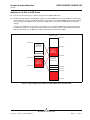
Figure 2: Physical Mapping of a NOR Flash Device When Flash Exceeds 4 MB ............................................ 41
Bro adco m Co rp or atio n
Document
110X_111X_119X-FAQ104-R
Page xiii
BCM110X/BCM111X/BCM119X
Frequently Asked Questions
10/15/08
Bro adco m C orp or atio n
Page xiv
Document
110X_111X_119X-FAQ104-R
Frequently Asked Questions
BCM110X/BCM111X/BCM119X
10/15/08
S e c t i on 1 : In t ro du c t i o n
This document provides answers to many of the questions frequently asked regarding the use of PhonexChange™ software.
This document applies to PhonexChange 3.6.
The following phone platforms are supported:
•
BCM91101 (Version 2)
•
BCM91103
•
BCM91103MP
•
BCM91103SP
•
BCM91104
•
BCM91104MP
•
BCM91104SP
•
BCM91190LB
REFERENCES
•
PhonexChange Software Development Guide
•
Resources for DHCP, Droms, R. Nov. 22, 2003. May 27, 2005 http://www.dhcp.org
•
DHCP FAQ, Droms, R. and T. Lemon. Oct. 26, 1998. May 27, 2005 http://www.dhcp-handbook.com/dhcp_faq.html
•
BCM1103 Gigabit IP Phone Chip Data Sheet
•
BCM1100/BCM1101/BCM113(R) Ethernet IP Phone Chips Data Sheet
•
BCM1190 VoIP Phone Chip Data Sheet
•
PhonexChange VxWorks Board Support Package
•
VxWorks® Application Programmer's Guide 6.6
•
VxWorks Kernel Programmer's Guide 6.6
•
Wind River® Network Stack for VxWorks 6 Programmer's Guide 6.6
•
VxWorks BSP Developer's Guide 6.6
•
PhonexChange Endpoint Module Technical Reference Manual
•
PhonexChange Ethernet Driver Technical Reference Manual
•
PhonexChange™ 802.1X Broadcom Supplicant Wrapper (BSW)
•
Broadcom Call Control SIP Protocol Abstraction Layer 1.10
•
PhonexChange Porting Guide
Bro adco m Co rp or atio n
Document
110X_111X_119X-FAQ104-R
Introduction
Page 1
BCM110X/BCM111X/BCM119X
Frequently Asked Questions
10/15/08
S e c t io n 2 : F r e q u e n t ly A s k e d Qu e s ti o ns
The information in this section is structured as follows:
•
Heading - Describes topic category.
•
The question and answer use the following Q and A format
Q:
Describes the question.
A:
Presents the answer.
APPTEST
KEY FEATURES
Q:
What key features are available in the ippConsole of the apptest application?
A:
Table 1 lists some of the more frequently used commands/features of the ippConsole.
Table 1: List of ippConsole Commands
Command
Description
?
List commands
help
List commands
chip
Prints chip information
ver
Prints the IPP version
reset
Resets board
cv
Call and Voice menu
COMMANDS AND CALL CONNECTIONS
Q:
How can I use apptest console commands to make a call connection, modify gains, play a tone, etc.?
A:
Refer to "Section 5: Test Call Client Application - Running the Test Call Client" in the PhonexChange Reference
Design Development Platform document.
Bro adco m C orp or atio n
Page 2
Frequently Asked Questions
Document
110X_111X_119X-FAQ104-R
Frequently Asked Questions
BCM110X/BCM111X/BCM119X
10/15/08
BCM1101 FAMILY
BCM1101 FAMILY FEATURE DIFFERENCES
The following table summarizes the differences in the BCM110X/BCM111X silicon family.
Table 2: Feature Differences in the BCM110X/BCM111X Silicon Family
BCM1101
BCM1113
BCM1115
150 MHz RISC
108 MHz DSP
3 (APM) CODECS
2 Ethernet ports
1 Ethernet switch
100 MHz RISC
108 MHz DSP
3 (APM) CODECS
2 Ethernet ports
1 Ethernet switch
150 MHz RISC
108 MHz DSP
2 (APM) CODECS
1 Ethernet port
No Ethernet switch
BCM1113R
BCM1115R
87 MHz RISC
87 MHz DSP
3 (APM) CODECS
2 Ethernet ports
1 Ethernet switch
87 MHz RISC
87 MHz DSP
2 (APM) CODECS
1 Ethernet port
No Ethernet switch
BDSL FILE FOR THE BCM1113 AND BCM1115
Q:
Where can I locate the BSDL file for the BCM1113 and BCM1115?
A:
The BCM1101 BSDL file is applicable to the BCM1113 and BCM1115 products, and is available in docSAFE on
Broadcom’s Customer Support Portal (CSP).
Bro adco m Co rp or atio n
Document
110X_111X_119X-FAQ104-R
BCM1101 Family
Page 3
BCM110X/BCM111X/BCM119X
Frequently Asked Questions
10/15/08
BCM1103 FAMILY
BCM1103 FAMILY FEATURE DIFFERENCES
The features listed in Table 3 summarize the differences between products in the BCM1103 silicon family.
Table 3: Feature Differences in the BCM1103 Silicon Family
BCM1103
BCM1104
275 MHz RISC
125 MHz MHz DSP
2 (APM) CODECS
2 10/100 Ethernet PHYs
1 Gigabit Ethernet switch
275 MHz RISC
NO DSP
2 (APM) CODECS
2 10/100 Ethernet PHYs
1 Gigabit Ethernet switch
BDSL FILES FOR THE BCM91104XX PLATFORMS
Q:
Where can I locate the BSDL files for the BCM91104xx platforms?
A:
The BCM1103 BSDL file is applicable to the BCM1104 device and is available in docSAFE Broadcom’s Customer
Support Portal (CSP).
BCM1103/1104 MIPS CORE
Q:
What MIPS® core is used in the BCM1103/1104?
A:
The BCM1103 and BCM1104 use the MIPS32® 4KC core with Broadcom DSP instruction extensions.
Bro adco m C orp or atio n
Page 4
BCM1103 Family
Document
110X_111X_119X-FAQ104-R
Frequently Asked Questions
BCM110X/BCM111X/BCM119X
10/15/08
BCM1190 FAMILY
BCM1190 FAMILY FEATURES
Features of the BCM1190 silicon family include:
•
275 MHz RISC
•
NO DSP
•
1 (APM) CODECS
•
2 10/100 Ethernet PHYs
•
Software Switch on MIPS core
BCM1190 MIPS CORE
Q:
What MIPS® core is used in the BCM1190?
A:
The BCM1190 use the MIPS32® 4KC core with Broadcom DSP instruction extensions.: the same MIPS core as on
the BCM1103 and BCM1104 devices.
Bro adco m Co rp or atio n
Document
110X_111X_119X-FAQ104-R
BCM1190 Family
Page 5
BCM110X/BCM111X/BCM119X
Frequently Asked Questions
10/15/08
BROADCOM CUSTOMER SUPPORT PORTAL PRODUCT CASES
Broadcom’s Customer Support Portal (CSP) product cases are presented in this section.
PRODUCT CASE NOTIFICATION
Q:
How do I notify my colleagues about a problem submitted to Product Cases?
A:
Include your colleagues' e-mail addresses in the Requester CC list field. The field is located under the Additional Info
tab of any case. When using this feature, an e-mail is sent to each e-mail address included in the list.
DOWNLOADING CASES
Q:
Is there a method to download all the cases to a local drive in case an Internet connection is lost?
A:
Presently, no download utility is available. However, the Query link can be used to build a query and specify Excel as
the output format. The query can then be issued at any time, and the output can be saved to an Excel spreadsheet.
The Query link is found under the Product Cases tab alongside the Submit Case, My Cases links.
SENDING QUESTIONS TO SUPPORT ENGINEERS
Q:
How do I send information, questions or discussions to support engineers in addition to the original question?
A:
Use the Requester Notes field under the General tab in the product case. When the field is updated, an e-mail is sent
to recipients involved in this case: requester, assignee, and individuals on the Requester CC list.
Q:
What kind of information should be included in the original question?
A:
In addition to the Project, Product, and Item fields, complete the following fields:
•
Software Version: The version number (e.g., PhonexChange 3.2.1.0) can be read from the
\phonex\build\config\release.h file.
•
Chip Revision: (e.g., BCM1103KPB) Provide the chip number marked on the chip.
•
Make sure to provide the following information in your original Case Description.
-
Reproducible: If you are reporting a bug, please let us know if the bug occurs intermittently, once, randomly
or is easily reproducible. If it is easily reproducible, provide the steps to reproduce the issue.
-
Triggering API Function: If PhonexChange API function that triggers the error is known, let us know.
If the question is related to an existing CSP case, link the case number to the question through the Related tab. The
Related tab accessible in the Modify mode.
Bro adco m C orp or atio n
Page 6
Broadcom Customer Support Portal Product Cases
Document
110X_111X_119X-FAQ104-R
Frequently Asked Questions
BCM110X/BCM111X/BCM119X
10/15/08
Q:
In addition to the Case Description, should logs be provided? If so, what kind of logs should be sent?
A:
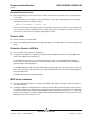
Provide the debug printout from the serial port for all questions. In addition, it is recommended that the following logs
be provided for each type of issue listed below.
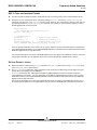
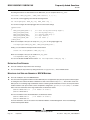
Flash Related Issues (e.g., problems writing and/or erasing certain sectors in the flash) The recommended log is the
serial port printout with the following extra setup:
•
At compile time, make sure CFI_DEBUG is defined in \phonex\bsp\vxWorks\common\bcm911xx\cfiamd.c.
•
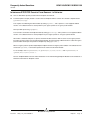
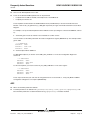
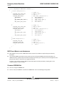
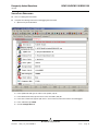
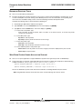
At runtime, query the problematic flash sector by entering the "d" command in the VxWorks Console. Below is a
screenshot of the command.
-> d 0x800f0000
800f0000: 27b5 0010 3c04 8022 2484 43a9 0016 2840 *'...<.."$.C...(@*
800f0010: 3c06 8022 0c03 68a0 24c6 43ae 0016 2840 *<.."..h.$.C...(@*
800f0020: 02a0 2025 0c04 49a9 2406 0020 8eee 0004 *.. %..I.$.. ....*
800f0030: 27de 0001 31ce 000f 01d6 001a 0000 0812 *'...1...........*
800f0040: 16c0 0002 0020 7021 0007 000d 2401 ffff *..... p!....$...*
800f0050: 16c1 0004 3c01 8000 15c1 0002 0000 0000 *....<...........*
800f0060: 0006 000d 03ce 082a 1420 ffe6 02b6 a821 *.......*. .....!*
800f0070: 1000 0066 0000 0000 0000 0000 0316 001a *...f............*
800f0080: 0000 0812 16c0 0002 0020 c021 0007 000d *......... .!....*
800f0090: 2401 ffff 16c1 0004 3c01 8000 1701 0002 *$.......<.......*
800f00a0: 0000 0000 0006 000d 171e 000c 2694 ffff *............&...*
800f00b0: 3c04 8022 2484 43b0 27a5 0010 3c06 8022 *<.."$.C.'...<.."*
800f00c0: 0c03 68a0 8cc6 30f4 27a4 0010 2405 0010 *..h...0.'...$...*
800f00d0: 0c04 49a9 2406 002e 0000 f025 3401 0002 *..I.$......%4...*
800f00e0: 12c1 0009 3c04 8022 3401 0004 12c1 000d *....<.."4.......*
800f00f0: 3c17 8022 3401 0008 12c1 0011 3c17 8022 *<.."4.......<.."*
•
Network or Protocol Related Issues (e.g., problems with SIP, ICMP or RTP packets) The recommended log is
the network packet analyzer log, such as Wireshark or Ethereal® log (you will need to connect your device to the
PC through a Hub in order to obtain the log through Wireshark or Ethereal).
•
Sound Quality or Endpoint related Issues (e.g., noisy output at the handset/headset) The recommended log is
a *.WAV file recording of the device output.
•
•
You may need to acquire a recording device, such as THAT-2, in order to make a recording.
•
You may also use the IORW utility for recording. See “How do I use the IO utility for audio
debugging?” on page 26.
All kinds of Assertion. You can identify an assertion when the following error messages are printed on the Serial
Port.
Tlb load exception
Exception program counter: 0x00000000
Status register: 0x1000ff01
Cause register: 0x00000008
Access address: 0x00000000
Task: 0x80eb8db0 "hwtk"
The recommended logs are the serial port log with all of the Debug messages before the above error messages,
and the the Memory Map file (app*.map) for your application which can be found in \phonex\bin\<Config
Profile> directory.
Bro adco m Co rp or atio n
Document
110X_111X_119X-FAQ104-R
Broadcom Customer Support Portal Product Cases
Page 7
BCM110X/BCM111X/BCM119X
Frequently Asked Questions
10/15/08
•
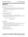
Ethernet Switch related issues, e.g., packet forwarding, routing-related issues, 802.1pQ Configuration, etc. The
recommended log is the serial port log with END Driver Verbose turned on.
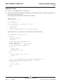
•
Turn on END Driver Verbose by typing the following commands in the VxWorks console.
- endFilter =1
- endRxVerbose=1
- endTxVerbose=1
•
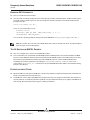
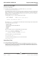
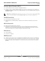
You will see the following printout in the serial port if these commands are executed successfully.
-> endFilter=1
endFilter = 0x8067b200: value = 1 = 0x1
> endRxVerbose=1
endRxVerbose = 0x8067b060: value = 1 = 0x1
-> endTxVerbose=1
endTxVerbose = 0x805ce680: value = 1 = 0x1
CAN PROPRIETARY INFORMATION BE POSTED ON THE WEB INTERFACE?
Q:
Can I post proprietary information on the web interface and will the information be sent to people that I am not aware
of?
A:
Information exchanged in the case is only viewable by members of your company working on the same project, other
authorized users provided by your company, and the Broadcom Customer Support team members. E-mail notices
generated from the information exchange only go to the requester and the members on the Request CC list.
CAN E-MAIL GENERATED BY PRODUCT CASES BE REPLIED TO DIRECTLY?
Q:
When receiving e-mail generated by product cases, can I reply to the e-mail directly instead of going through the web
interface?
Q:
What are the implications?
A:
Yes, the e-mail can be responded to directly. And, either way, information is logged into the Product Cases system.
However, when replying through e-mail, delete the content of the notification e-mail to avoid cluttering the system.
WHAT HAPPENS WHEN REPLIED-TO E-MAIL IS NOT RECEIVED BY THE SYSTEM?
Q:
When I replied to the e-mail directly, according to procedure, the e-mail was never received by the system. Why did
that happen?
A:
You may be replying to CSP with a user e-mail address that has not been registered with the system. Please contact
Broadcom to register the user for CSP usage.
BSP
CHANGING THE END DEVICE NAME
Q:
How do I change the end device name from the default bcm?
A:
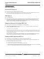
You can change the end device name by modifying the define END_DEVICE_NAME in
\phonex\bsp\vxWorks\<BSP profile>\config.h
Bro adco m C orp or atio n
Page 8
BSP
Document
110X_111X_119X-FAQ104-R
Frequently Asked Questions
BCM110X/BCM111X/BCM119X
10/15/08
BUILD ENVIRONMENT
PLATFORM CD 3.6 INSTALLATION
Q:
How do I install PCD 3.6?
A:
Refer to the “Platform CD 3.6 Installation” section in the PhonexChange Software Development Guide and the Release
Notes for PCD 3.6 patches.
CLEAN BUILDS
Q:
What is a clean build?
A:
A clean build removes the object files and libraries associated with the target. For more information on a clean build,
refer to the section “PhonexChange™ Build Environment” of the PhonexChange Software Development Guide.
BUILD ABORTED FOR NO APPARENT REASON
Q:
The build aborts for no apparent reason, and the following error messages appear in the shell window. What should I
do?
A:
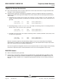
The compiler may leave intermediate files in a temporary folder when a previous build was stopped by pressing
<CTRL-C>. You need to manually remove all files from the temporary folder to resolve this issue. You can locate the
temporary folder by querying the environment variable—TEMP with the Set command.
CREATING A NEW PLATFORM PROFILE
Q:
Why should we create a new platform profile?
A:
The IP Phone build environment includes support for configuration profiles that can be used to define a specific IP
Phone configuration. A new configuration profile can be used to store build information for a specific platform. The
profile is stored in the folder \phonex\build\config\<config profile>, where <config profile> is the name of
the configuration profile.
CREATING A NEW PLATFORM PROFILE PROCEDURE
Q:
How can I create a new platform profile?
A:
You can create a new profile by following the procedures in PhonexChange Build Environment - Configuration Profiles
of the PhonexChange Software Development Guide.
Bro adco m Co rp or atio n
Document
110X_111X_119X-FAQ104-R
Build Environment
Page 9
BCM110X/BCM111X/BCM119X
Frequently Asked Questions
10/15/08
BUILDING A NEWLY ADDED FILE
Q:
How can I build a newly added file in our boot code?
A:
You can add the file to phonex/bsp/vxWorks/<platform> (eg. custom.c) and modify the file Makefile within the directory
as follows:
# Additional source code that resides in the BSP directory
MACH_EXTRA = \
bcmIPHalEnd.o \
bcmBoard.o \
bcmCache.o \
bcmBsp.o \
custom.o
Q:
How can I build a newly added file in our application code?
A:
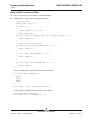
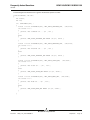
Modify the makefile within the folder that contains the newly added file. For example, if you want to add ccUser.c to
the folder \phonex\mcu\cc\test, you need to update the makefile located in the same directory of your source file.
Since libcctest.mk is the makefile located in the \phonex\mcu\cc\test directory, you need to add ccUser.c
to the list of source files. The following illustrates the example.
Bro adco m C orp or atio n
Page 10
Build Environment
Document
110X_111X_119X-FAQ104-R
Frequently Asked Questions
BCM110X/BCM111X/BCM119X
10/15/08
###########################################################################
#
# This makefile is used to build libcctest.a library and the library is
# located at \phonex\lib\<BSP Profile>
#
###########################################################################
# --------------------------------------------------------------------------# This should match the target name.
#
XCHG_LIB_BASE := libcctest
CCTEST_ROOT
:= $(IPP_XBE_DIR_$(XCHG_LIB_BASE))
# --------------------------------------------------------------------------# List of all source files. Do not specify directories, we use vpath below.
#
XCHG_SRC_FILES_$(XCHG_LIB_BASE) := \
kbdprv.c \
ccData.c \
cctest.c \
ccstore.c \
ccUser.c \
htmlTest.c \
ccPhoneCfg.c
XCHG_SRC_FILES += $(XCHG_SRC_FILES_$(XCHG_LIB_BASE))
# We use vpath so that the object files don't wind up in nested subdirectories.
# These must be absolute paths in order to support non-recursive makefiles.
#
vpath %.c $(CCTEST_ROOT) $(CCTEST_ROOT)/..
# --------------------------------------------------------------------------# Add in private directories that are only needed when compiling this library.
# These must be absolute paths in order to support non-recursive makefiles.
#
XCHG_C_LOCAL_INCLUDE_$(XCHG_LIB_BASE) := ${CCTEST_ROOT}/..
# --------------------------------------------------------------------------# Add in private defs that are only needed when compiling this library.
#
XCHG_C_LOCAL_DEFS_$(XCHG_LIB_BASE) :=
# --------------------------------------------------------------------------# Add in private compile options that are only needed when compiling this library.
#
XCHG_C_LOCAL_COMPILER_OPTS_$(XCHG_LIB_BASE) :=
# ---------------------------------------------------------------------------
Bro adco m Co rp or atio n
Document
110X_111X_119X-FAQ104-R
Build Environment
Page 11
BCM110X/BCM111X/BCM119X
Frequently Asked Questions
10/15/08
#
#
#
#
#
#
#
#
#
To set a module specific compiler option, create a target specific make
variable which sets the option and depends on the module target name.
For example, to enable compiler optimizations for this module:
$(XCHG_LIB_BASE): XCHG_C_OPTIMIZE_OPT = $(XCHG_C_OPTIMIZE_OPT_ENABLE)
or, to disable optimizations:
$(XCHG_LIB_BASE): XCHG_C_OPTIMIZE_OPT = $(XCHG_C_OPTIMIZE_OPT_DISABLE)
BUILDING A NEWLY ADDED LIBRARY (FOLDER)
Q:
How can I build a newly added library (folder)?
A:
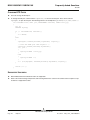
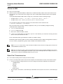
1. Add the software module under the phonex directory by creating its own subdirectory "<NEW_MODULE>" and by
adding a new "lib<NEW_MODULE>.mk" file in the subdirectory with the following lines:
XCHG_LIB_BASE := lib<NEW_MODULE>
<NEW_MODULE>_ROOT := $(IPP_XBE_DIR_$(XCHG_LIB_BASE))
2. Modify \phonex\ipp_xbe_targets.mk.
a. Add new library to the list of all targets, IPP_XBE_ALL_TARGETS.
IPP_XBE_ALL_TARGETS := \
…
lib<NEW_MODULE> \
…
b. Add an entry for the new module's directory.
IPP_XBE_DIR_lib<NEW_MODULE> := $(IPP_XBE_ROOT)/###/<NEW_MODULE>
where ### is the parent directory of the new module.
c. Add an entry for the new module's public includes.
IPP_XBE_PUBLIC_INC_<NEW_MCU_MODULE> := $(IPP_XBE_ROOT)/###/inc
where ### is the parent directory of the new module.
3. Modify \phonex\build\app_ipphone_libsgroup.mk. Add the new library to the group to which it belongs.
a. Add "lib<NEW_MODULE>.a" under LIBS_###, where ### is the group.
4. Modify \phonex\build\phonex_xbe_rules.mk to include directories for the new module. The following is an example
of included directories:
export lib<NEW_MODULE>_cinc = \
${IPP_XBE_ROOT}/util/inc \
${IPP_XBE_ROOT}/build/config/${CONFIG} \
${IPP_XBE_ROOT}/build/config \
${IPP_XBE_ROOT}/bsp/bcm/bcmBoard/inc \
${IPP_XBE_ROOT}/bsp/${IPPCFG_BSP_COMMON}
Bro adco m C orp or atio n
Page 12
Build Environment
Document
110X_111X_119X-FAQ104-R
Frequently Asked Questions
BCM110X/BCM111X/BCM119X
10/15/08
WIND RIVER PCD3.6 COMPATIBILITY
Q:
Is Wind River's PCD3.6 compatible with previous versions of Tornado®?
A:
Wind River's PCD3.6 is not compatible with previous versions of Tornado. All source files need to be recompiled
(conduct a clean build before recompile).
MAKEFILE FORMAT
Q:
What is the format of a makefile?
A:
A simple makefile consists of rules with the following format:
target ... : dependencies ...
command
...
...
A target is usually the name of a file generated by a program. Examples of targets are executables or object files.
Dependencies are files that are used as input to create the target. A target often depends on several files. A command
is an action that make performs. A rule may have more than one command, each on its own line.
ADDING CUSTOM DEFINES TO MAKEFILE
Q:
How can I add custom defines to makefiles?
A:
To add a custom define to your build, refer to “PhonexChange Build Environment - Configuration Profiles” in the
PhonexChange Software Development Guide . To add a custom define within your library, add the custom define in
the following way:
CFLAGS += -D<custom_define>
Bro adco m Co rp or atio n
Document
110X_111X_119X-FAQ104-R
Build Environment
Page 13
BCM110X/BCM111X/BCM119X
Frequently Asked Questions
10/15/08
ENDPOINT
ADAPTIVE JITTER BUFFER
Q:
What is an adaptive jitter buffer?
A:
An adaptive jitter buffer dynamically adapts to network conditions to ensure smoothness during playback. For a
detailed description, refer to "Appendix E. Adaptive Jitter Buffer" in the PhonexChange Endpoint Module Technical
Reference Manual.
JITTER BUFFER RECOMMENDED SETTINGS
Q:
What are the recommended settings for the jitter buffer?
A:
We strongly recommend using the default settings for the jitter buffer. To use the default settings, set useDefaults to
TRUE in the jitter buffer configuration structure (see the previous question). The rest of the parameters are "don't care"
(they will be ignored if useDefaults is set to TRUE). The default settings are:
•
jitterMin = 0 ms
•
jitterMax = 0 ms
•
jitterTarget = 0 ms
However, if there is a known non-zero minimum network jitter, you can set the jitterTarget to that value to prevent
underflow.
In addition, since the default jitterMax is 0, the jitter buffer will adapt to the maximum allowable holding time, which is
limited by the available jitter buffer memory allocation.
When the default values are used and the network doesn't produce any jitter, the adaptive jitter buffer may produce
odd results in the case of high clock drift (about 200 ppm). With no jitter, it finds no reason to hold packets before they
are played, and therefore, plays out packets whenever they are received. However, if the two systems' clocks are
different (clock drift), the adaptive jitter buffer may sometimes under-run because one clock is slower than the other.
As a result, you may encounter odd performance results (again, only when clock drift is high, around 200 ppm).
CONTROLLING BEHAVIOR OF ADAPTIVE JITTER BUFFER
Q:
How do I control the behavior of the adaptive jitter buffer?
A:
It is highly recommended that the user always use the default jitter buffer settings. The endpoint module can control
the behavior of the adaptive jitter buffer through the data structure EPTJITTERBUF. However, we strongly
recommend default jitter buffer settings be used.
Refer to "Appendix E. Defining the Adaptive Jitter Buffer Configuration" of the PhonexChange Endpoint Module
Technical Reference Manual for more information on the EPTJITTERBUF data structure.
.
Bro adco m C orp or atio n
Page 14
Endpoint
Document
110X_111X_119X-FAQ104-R
Frequently Asked Questions
BCM110X/BCM111X/BCM119X
10/15/08
ADAPTIVE JITTER BUFFER STATISTICS
Q:
How can we obtain the adaptive jitter buffer statistics?
A:
Refer to Appendix E. Obtaining the Adaptive Jitter Buffer Statistics of the PhonexChange Endpoint Module Technical
Reference Manual.
ADAPTIVE JITTER BUFFER STATISTICS INTERVAL
Q:
How do I change the jitter buffer statistics generation interval?
A:
You can change the jitter buffer statistics generation interval at run-time through the serial port by:
1. Starting the BRCM console by typing the following command at the prompt:
> console
2. Starting the Voice Over IP Menu by typing the following command at the prompt:
> voip
3. Entering the desirable internal <n> in milliseconds (ms).
> interval <n>
RTP STATISTICS AND JITTER REPORTS
Q:
What is the limitation in retrieving the jitter report in the RTP Statistics?
A:
The RTP statistics are updated internally once every 200 ms in the endpoint module. The interval of the query is
defined by the symbolic constant EPT_HAPIGET_INTERVAL in \phonex\mcu\inc\ept.h. If you query statistics
more frequently than the internal updates, the statistics reported may not have been updated since the last query and
will be stale. For more information regarding to RTP/RTCP statistics, refer to “RTP/RTCP Packets” under the
“Examples” section in the latest PhonexChange Endpoint Module Technical Reference Manual.
ACCESSING THE IOM2 AUDIO CHANNEL
Q:
How do I access the IOM2 audio channel?
A:
IOM-2 is no longer supported by PhonexChange.
BROADCOM ECAN TAIL LENGTH
Q:
What are the tail lengths for the Broadcom ECAN and AEC? How can we change them?
A:
The tail lengths are set to 16 ms (32 ms for the BCM1103) and 96 ms for Broadcom ECAN and Broadcom AEC
respectively. You must not change these settings because these values are optimized for Broadcom IP Phone
applications.
Bro adco m Co rp or atio n
Document
110X_111X_119X-FAQ104-R
Endpoint
Page 15
BCM110X/BCM111X/BCM119X
Frequently Asked Questions
10/15/08
DEFAULT PLC MODE
Q:
What is the default PLC mode? Can we change it at run-time?
A:
Different default PLC modes are set up for different vocoders. Details of each of these PLC modes are covered in
“Appendix B: Packet Loss Concealment” in the PhonexChange Endpoint Module Technical Reference Manual.
You can change the PLC mode at run-time through the function: eptModifyStream(). Refer to the Endpoint Module
Technical Reference Manual for more information.
VAD VALUES
Q:
What does each level value do when I turn on the VAD?
A:
The level range of VAD (or silence suppression) is from EPTSILSUP_LEVEL_MIN to EPTSILSUP_LEVEL_MAX, with
a larger value corresponding to a more aggressive setting. The level does not matter if the mode field of the
EPTSILSUP structure is set to "EPTSILSUP_OFF".
EQUALIZATION FILTER
Q:
How do I use the Equalization Filter?
A:
Refer to “Equalizer Filter” in “Signal Generation” under “Examples” in the PhonexChange Endpoint Module Technical
Reference Manual.
HIGH-PASS FILTER
Q:
What are the properties of the high-pass filter inside Endpoint that conditions audio signals to and from codecs? Can
I disable the filter?
A:
The digital high-pass filter implements the follow difference equation:
y[i] = (1-alpha) * y[i-1] +
( x[i] - x[i-1] )*(1-alpha/2)
where alpha = 2^5
This filter has no gain in the pass-band, and a 3 dB point at about 40 Hz.
The high-pass filter should never be disabled; otherwise; it leads to unpredictable behavior.
CUSTOMIZING TONES AND RINGS
Q:
How can I create a customized tone/ring?
A:
Refer to “Signal Generation” in the section “Signal Generation” under “Examples” in the PhonexChange Endpoint
Module Technical Reference Manual.
GENERATING TONES AND RINGS (INGRESS)
Q:
How can I generate a tone/ring into the network (ingress)?
A:
You can generate a tone/ring into the network by following the example for generating a tone/ring shown in the “Signal
Generation” section under Examples in the PhonexChange Endpoint Module Technical Reference Manual.
Bro adco m C orp or atio n
Page 16
Endpoint
Document
110X_111X_119X-FAQ104-R
Frequently Asked Questions
BCM110X/BCM111X/BCM119X
10/15/08
GENERATING TONES AND RINGS (EGRESS)
Q:
How can I generate a tone/ring locally (egress)?
A:
You can generate a tone/ring locally by following the example for generating a tone/ring provided in “Signal
Generation” under “Examples” in the PhonexChange Endpoint Module Technical Reference Manual.
GENERATING TONES AND RINGS (EGRESS AND INGRESS)
Q:
How do I generate a tone/ring locally (egress) and into the network (ingress)?
A:
To do this, follow the example for generating a tone/ring provided in “Signal Generation” under “Examples” in the
PhonexChange Endpoint Module Technical Reference Manual.
CHANGING VOICE VOLUME WITHOUT CHANGING TONE VOLUME
Q:
I am playing voice and tone locally (egress) at the same time. How can I change the voice volume without changing
the tone volume?
A:
Use eptModifyStream() to modify the Voice Volume gain block setting. This is done by changing the
voice.egressVoiceLevelDb element in the parameter set passed to eptModifyStream(). Changing the Voice
Volume gain block only changes the voice volume; it will not change the tone volume. See “Volume and Gain Control”
under “Examples” in the PhonexChange Endpoint Module Technical Reference Manual.
RESTARTING TONE GENERATION
Q:
Do I need to restart the tone generation in a stream when I attach the stream to another device?
A:
No. The tone should be heard at the second device once the stream is attached to the other device. There is no need
to regenerate the tone.
ATTENUATING TONE
Q:
The tone volume level in EPTSIGTONEPARM ranges from 0 to -95 dB. Does this mean that I can only attenuate the
tone?
A:
Yes, it means that you can only attenuate the tone volume level and cannot boost the tone level. The maximum level
is 0 dB.
DB LEVEL
Q:
When the direction field in EPTSIGTONEPARM is EGRESS_AND_INGRESS, does the dB level affect the gain of both
egress and ingress signals?
A:
No, the dB level is set up separately by using the parameters ingressSignalLevelDb and
egressSignalLevelDb. For more information, see “Signal Generation” under “Examples” in the PhonexChange
Endpoint Module Technical Reference Manual.
Bro adco m Co rp or atio n
Document
110X_111X_119X-FAQ104-R
Endpoint
Page 17
BCM110X/BCM111X/BCM119X
Frequently Asked Questions
10/15/08
GENERATING AN RFC2833 DTMF TONE
Q:
How do I generate an RFC2833 DTMF tone?
A:
Refer to “Tone Relay of Signal Generation” under “Examples” in the PhonexChange Endpoint Module Technical
Reference Manual for examples on generating an RFC2833 DTMF tone.
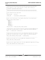
VERIFYING RFC2833 DTMF TONES
Q:
How do I know RFC2833 DTMF tones are actually generated?
A:
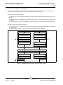
When the user enables tone relay and presses a digit during a call, packets with the following RTP payload are sent
into the network. For more information about the payload, refer to:
http://www.ietf.org/rfc/rfc2833.txt.
0
1
2
3
0 1 2 3 4 5 6 7 8 9 0 1 2 3 4 5 6 7 8 9 0 1 2 3 4 5 6 7 8 9 0 1
+-+-+-+-+-+-+-+-+-+-+-+-+-+-+-+-+-+-+-+-+-+-+-+-+-+-+-+-+-+-+-+-+
|
event
|E|R| volume
|
duration
|
+-+-+-+-+-+-+-+-+-+-+-+-+-+-+-+-+-+-+-+-+-+-+-+-+-+-+-+-+-+-+-+-+
DETERMINING RTP PAYLOAD TYPES
Q:
How is the RTP payload type determined when generating DTMF tones according to the RFC2833 standard?
A:
According to the RFC2833 standard, the RTP payload type is determined dynamically.
Bro adco m C orp or atio n
Page 18
Endpoint
Document
110X_111X_119X-FAQ104-R
Frequently Asked Questions
BCM110X/BCM111X/BCM119X
10/15/08
INTERFACING RTP/RTCP PACKETS FROM ENDPOINT TO NETWORK
Q:
How are RTP/RTCP packets passed between Endpoint and network?
A:
The RTPT (RTP Transport) module is used to interface Endpoint with the network. This module is implemented in
(\phonex\mcu\rtpt).
This requires first initializing the RTPT module by calling rtptInit() with a pointer to a user-supplied callback
function. The callback function is used by RTPT to pass egress packets to an egress packet handler.
Next open RTP ports using rtptOpen().
The next task is to initialize the Endpoint module by calling eptStartup() with a pointer to a user-supplied callback
function. The callback function is used by Endpoint to pass ingress packets to an ingress packet handler.
After RTPT is initialized and ports are opened, the RTPT module starts the "RTPT" task to receive egress packets.
Each time an egress packet is received by the RTPT module, the egress packet callback function is called. The egress
packet handler should pass the packet into Endpoint by calling eptPacket().
When an ingress packet is produced by Endpoint, Endpoint invokes the ingress packet callback. The callback function
should call rtptSend() to forward the packet into the network via the RTPT module.
For an example, refer to egressPktCb() in \phonex\mcu\cc\test\cctest.c and ingressPktCb() in
\phonex\mcu\cc\test\cctest.c.
Refer to "Endpoint Module Context" under "Introduction" in the PhonexChange Endpoint Module Technical Reference
Manual for information on Endpoint context.
Bro adco m Co rp or atio n
Document
110X_111X_119X-FAQ104-R
Endpoint
Page 19
BCM110X/BCM111X/BCM119X
Frequently Asked Questions
10/15/08
CHANGING RTP PORTS
Q:
How can I change the RTP port?
A:
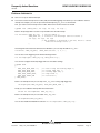
To change the RTP port, call the function rtptClose() to close the unused port. Then, call the function
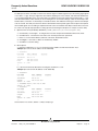
rtptOpen() to open the new port. The following function is an example from \phonex\mcu\cc\test\cctest.c.
int ccTestMulticast( BOOL join, EPTSTREAMID streamId, UINT32 mcast_ip )
{
int rc;
RTPTCFG rtptCfg;
if ( ! streamIdValid( streamId ) )
{
rc = FALSE;
}
else
{
rtptCfgGet( cnxParm[streamId].rtptHandle, &rtptCfg );
/* close the RTPT port then reopen it */
rtptClose( cnxParm[streamId].rtptHandle );
if ( join )
{
rtptCfg.srcAddr = mcast_ip;
}
else
{
rtptCfg.srcAddr = 0;
}
rc = (int)rtptOpen( &cnxParm[streamId].rtptHandle, &rtptCfg );
}
return ( rc );
}
SUPPORTED VOCODERS
Q:
Which wideband and narrowband vocoders are supported?
A:
Refer to the “PhonexChange Components and Licensing Restrictions” section in the software release report for an upto-date list of supported vocoders.
Bro adco m C orp or atio n
Page 20
Endpoint
Document
110X_111X_119X-FAQ104-R
Frequently Asked Questions
BCM110X/BCM111X/BCM119X
10/15/08
TROUBLESHOOTING AUDIO HANDSET
Q:
There is no audio in the handset after I bind the EPT device EPTDEV_NLP_1 from APM handset to an external HSS
device. Why does that happen?
A:
There are only 3 EPT DEVICES in the EPT software. Binding binds an EPT DEVICE to an APM or HSS interface.
Since we have only 3 EPT DEVICES, there can only be three working devices at one time.
EPTDEV_NLP_1
EPTDEV_NLP_2
EPTDEV_FDS
for handset
for headset
for handsfree
If EPTDEV_NLP_1 is rebound from the APM handset to HSS, then the APM handset loses the binding with
EPTDEV_NLP_1. As the result, the handset no longer has audio.
NOISE AND SATURATION
Q:
I am hearing noise/saturation. Where are the gain blocks? What are their default values?
A:
The gain blocks of the BCM1100/BCM1101 and BCM1103 chips are covered in the "Gains and Sidetone in the Signal
Path" section of the PhonexChange Software Development Guide.
RESETTING RTP STATISTICS COUNTERS
Q:
Why does it appear that egressRtpCumLostPkt counter is not reset after I call eptModifyStream() with
resetStats flag set to TRUE?
A:
The egressRtpCumLostPkt counter specifies the cumulative packet loss of the RTP/RTCP session. This field is
updated whenever an egress RTCP packet is received. If you reset the counter, and an RTCP packet arrives BEFORE
you poll the counter, the counter becomes non-zero and appears as if the reset had no effect.
UNITS FOR RTP STATISTICS
Q:
What are the units for ingressRtpLatency and egressRtpJitter in EPTRTPSTAT structure?
A:
When using narrowband codecs, they are both in units of 125us. When using wideband codecs,
ingressRtpLatency is still in units of 125us, but egressRtpJitter is in units of 62.5us.
STATISTICS INCREMENTING CONDITIONS
Q:
Under what conditions is the egressRtpDiscardPkt field in EPTRTPSTAT structure incremented?
A:
The egressRtpDiscardPkt is incremented when egress RTP and RTCP packets are dropped by Endpoint. They
are dropped under the following situations when:
•
There is error in RTP/RTCP header (i.e. invalid length, version, padding, and so forth.)
•
The size of the packet does not match the type of vocoder used.
•
The specified vocoder is not supported.
•
The NTE (named telephone event) event range is not supported
•
The RTCP type is not defined (i.e. not SR, RR, SDES, BYE, and APP, as defined in RFC3550).
Bro adco m Co rp or atio n
Document
110X_111X_119X-FAQ104-R
Endpoint
Page 21
BCM110X/BCM111X/BCM119X
Frequently Asked Questions
10/15/08
RTP STATISTICS DIFFERENCES
Q:
What is the difference between egressRtpDiscardPkt and egressRtpCumLostPkt fields in the EPTRTPSTAT
structure?
A:
egressRtpDiscardPkt indicates the number of packets dropped by Endpoint. egressRtpCumLostPkt indicates
the packets lost in the network.
SRTP
Q:
How do I set up SRTP?
A:
SRTP parameters are contained as a part of the stream parameters. These values can be sent to endpoint using
eptCreateStream() or eptModifyStream(). An example of configuring SRTP can be found in
phonex\mcu\cc\test\cctest.c in the function ccTestSetSrtp(). The ingress and egress settings are configured
independently.
Q:
Is the code supplied for SRTP and SRTCP certified?
A:
Based on the FIPS140-2 standard, our SMAPI-SRTP SW stack is compliant with the "FIPS 140-2, Level-1"
requirements, though it has not gone through formal certification. If certification is required, it should be made the part
of the software development process.
MAXIMUM PACKETIZATION VALUES
Q:
I have seen a maximum value of 90 ms packetization period in the ept.h file. Can I use this value on any vocoder when
I create or modify a stream? Can I use a value greater then 90 ms?
A:
The range of packetization period that is supported on each vocoder is listed in the PhonexChange software release
report. You can set the packetization period to any value that is within the range, with the restriction that the period
must be a multiple of the vocoder's base packetization period.
The maximum packetization period for each vocoder is also defined in \phonex\mcu\inc\ept.h as
EPT_MAX_PKTPRD_xxx.
Note: If the packetization period is set outside of the range the DSP will return a HAPI error. Below is an example:
hdspEvntCb: NetVHD handle 80. Error evt =
HAPI_CODEC_EXCEPTION_EVT(PVEEXCEPTION_SUPERINTERVAL). max packet size = 640 bytes
MAPPING ENDPOINT DEVICES TO APM CODECS
Q:
How do I map endpoint devices to APM codecs?
A:
The procedure to map endpoint devices is in “Appendix C: Defining Platform Specific Audio Configuration” of the
PhonexChange Endpoint Module section of the Technical Reference Manual.
Bro adco m C orp or atio n
Page 22
Endpoint
Document
110X_111X_119X-FAQ104-R
Frequently Asked Questions
BCM110X/BCM111X/BCM119X
10/15/08
CONTROLLING APM AND PGA GAINS
Q:
How do I control the APM PGA gains on BCM1103/BCM1104?
A:
Instructions on how to control the APM gains are in the “Appendix C: Defining Platform Specific Audio Configuration”
section of the PhonexChange Endpoint Module Technical Reference Manual.
SIDETONE DELAY
Q:
What is the sidetone delay?
A:
For the BCM1101/BCM1100, sidetone is generated in the DSP software, so the delay includes the media queue
buffering time in the DSP software. A 2.5 ms delay is introduced during ingress sampling and an additional 2.5 ms
delay is introduced during egress sampling. The total sidetone delay is therefore 5 ms.
For the BCM1103/BCM1104/BCM1190, the sidetone is implemented in hardware inside the APM block. The estimated
sidetone delay is in the order of 10's of μsec. The sidetone delay is mainly introduced from the Y-filter of the APM,
where the sidetone is generated at 100 kHz sampling frequency. A negligible delay is also introduced from the rest of
the sidetone pathway through the CIC filter and the analog path. The block diagram of the APM path is shown in the
“APM Block Diagram” of the applicable data sheet.
Bro adco m Co rp or atio n
Document
110X_111X_119X-FAQ104-R
Endpoint
Page 23
BCM110X/BCM111X/BCM119X
Frequently Asked Questions
10/15/08
APM LOOPBACKS ON THE BCM1103, 1104, AND 1190
Q:
How can I do APM loopback on the 1103 or 1104
A:
There are two different APM loopbacks that can be performed:
•
Loopback from the ADC to the DAC, which skips most of the APM blocks
•
Loopback just after the CIC
These loopbacks are illustrated in the BCM1103 Data Sheet (1103-DS10x-R) in “Section 10: Audio Processor
Module”. Refer to adc_dac_lpbk and tx_rx_100k_lpbk respectively in “Figure 10-7: Audio Channel Processor (ACP)
Block Diagram”.
For example, to set up a handset loopback from the VxWorks console (assuming it is connected to CODEC 0,
channel A):
1. Set the RX gain of Codec 0, channel A since it defaults to 0, which is mute.
You must also set the VRX_PGA field in the Codec Configuration-5 register (0xBAFE4114). This example sets the
gain to 0 dB:
-> m 0xbafe4114
bafe4114: 0000bafe4116: 0000-1500
bafe4118: 0000-q
value = 1 = 0x1
2. Set the loopback bit for CODEC 0.
For ADC-DAC loopback, you must set the ADC_DAC_LPBK bit to 1 in the Test Configuration Register for
Channel A:
-> m 0xbafe4018
bafe4018: 0000bafe401a: 4448-4548
bafe401c: 0000-q
For the CIC loopback, you must set the TX_RX_100K_LPBK bit to 1 in the same register:
-> m 0xbafe4018
bafe4018: 0000bafe401a: 4448-4468
bafe401c: 0000-q
These steps assume that your code has not changed the mux to use channel B, i.e., VTX_PGA_MUX of CODEC
Configuration-3 Register is set to input A (0xBAFE410c).
Bro adco m C orp or atio n
Page 24
Endpoint
Document
110X_111X_119X-FAQ104-R
Frequently Asked Questions
BCM110X/BCM111X/BCM119X
10/15/08
Q:
How can I do APM loopback on the 1190?
A:
There are two different APM loopbacks that can be performed:
•
Loopback from the ADC to the DAC, which skips most of the APM blocks
•
Loopback just after the CIC
These loopbacks are illustrated in the BCM1190 Data Sheet (1190-DS10x-R) in “Section 10: Audio Processor
Module”. Refer to adc_dac_lpbk and tx_rx_100k_lpbk respectively in “Figure 10-4: Audio Channel Processor Block
Diagram”.
For example, to set up a handset loopback from the VxWorks console (assuming it is connected to CODEC 0, channel
A):
1. Set the RX gain of Codec 0, channel A since it defaults to 0, which is mute.
You also need to set the VRX_PGA field in the Codec Configuration-5 register (0xBAFE4114). This example setsthe
gain to 0 dB:
-> m 0xbafe4114
bafe4114: 0000bafe4116: 00a4-15a4
bafe4118: dead2. Set the loopback bit for CODEC 0.
For ADC-DAC loopback, you need to set the ADC_DAC_LPBK bit to 1 in the Test Configuration Register for
Channel A:
-> m 0xbafe4018
bafe4018: 0000bafe401a: 4040-4140
bafe401c: dead-.
For the CIC loopback, you need to set the TX_RX_100K_LPBK bit to 1 in the same register:
-> m 0xbafe4018
bafe4018: 0000bafe401a: 4040-4060
bafe401c: dead-.
These steps assume that your code has not changed the mux to use channel B, i.e., VTX_PGA_MUX of CODEC
Configuration-3 Register is set to input A (0xBAFE410c).
AEC
Q:
Where are the AEC parameters defined?
A:
The AEC parameters are defined in the \phonex\build\config\<config profile>\spkrphonecfg.h file.
Once the AEC parameters are determined from tuning, spkrphonecfg.h should be modified.
Bro adco m Co rp or atio n
Document
110X_111X_119X-FAQ104-R
Endpoint
Page 25
BCM110X/BCM111X/BCM119X
Frequently Asked Questions
10/15/08
Q:
How do I use the IO utility for audio debugging?
A:
The "io" utility is a feature to record/inject a signal before and after the AEC block. This utility can help debug most
audio issues users encounter. The "io" utility is a command in the AEC console menu.
The utility can record at three locations:
•
r1 = BOS receive record - signal after the AEC block in egress direction, right before the signal is played out to the
speaker.
•
r2 = BOS send record - signal before the AEC block in ingress direction, right after the signal is recorded by the
microphone.
•
r3 = PVE send record - signal after the AEC block in ingress direction. This is only supported in 1104 and 1190.
The utility can also inject signal at two locations:
•
i1 = PVE receive inject - a signal can be injected before the AEC block in egress direction. This is only supported
in 1104 and 1190.
•
i2 = BOS send inject - a signal can be injected before the AEC block in ingress direction.
Endpoint Stream
RTP
RTP
Net
Net
Packet Voice Exchange (PVE)
Packet Voice Exchange (PVE)
r3
i1
AGC
Packet Tone Exchange (PTE)
Packet Tone Exchange (PTE)
PCM
Switch board
Endpoint Stream
ECAN/AEC
ECAN/AEC
Line Service
Line Service
r2
r1
i2
Figure 1: Debugging with the I/O Utility, Record or Inject a Signal
Bro adco m C orp or atio n
Page 26
Endpoint
Document
110X_111X_119X-FAQ104-R
Frequently Asked Questions
BCM110X/BCM111X/BCM119X
10/15/08
For both inject locations, the utility can either over-write the signal or add the signal on top of the existing signal (prefix
i1 or i2 with a '+' sign). The inject signal must be in 16kHz sampling rate, mono channel, and 16-bit Intel PCM format.
ev is used for logging AEC events. If you don't wish to record/inject at any point, replace the parameter with a '-' sign.
chan determines which codec channel you are recording from. In our reference design, codec 0 is hooked up to the
handset device, and codec 1 is hooked up to a handsfree device. time indicates how long you want the record/inject
to be in seconds. The utility uses the FTP clients to download the to-be-injected signals onto the phone and upload
the recorded signals once recording is completed. An FTP server is needed for this utility to transfer files to the host
PC. Here is the step-by-step operation for setting up FTP and ensuring that the phone is ready to use the io utility:
1. Open the FTP server provided by Wind River ($(WIND_BASE)host\x86-win32\wftpd32.exe).
a. Click Security > Users/rights... to configure the user name and password allowed from the FTP clients.
b. Click New User... and enter the user name "user" and the password as "password".
c. Enter "C:\" for the Home Directory text book, and select "Restricted to home".
d. Click Rights >> and enter "c:\rdata\" for the Directory textbox.
e. Click Done to save the setting.
2. On the phone:
a. Enter the command "hostShow" to ensure the host IP address is under the hostname "host".
Example: (the host has the IP address of 192.168.0.100)
-> hostShow
hostname
inet address
------------------localhost 127.0.0.1
target
192.168.0.130
host
192.168.0.100
value = 0 = 0x0
->
aliases
-------
b. If the host is not listed, add it to the list using the command hostAdd.
Example: (the host have the IP address of 192.168.0.100)
-> hostShow
hostname
inet address
aliases
------------------------localhost
127.0.0.1
target
192.168.0.130
value = 0 = 0x0
-> hostAdd "host","192.168.0.100"
value = 0 = 0x0
-> hostShow
hostname
inet address
aliases
------------------------localhost
127.0.0.1
target
192.168.0.130
host
192.168.0.100
value = 0 = 0x0
->
Go back to the AEC console, and the io utility is ready to go.
Bro adco m Co rp or atio n
Document
110X_111X_119X-FAQ104-R
Endpoint
Page 27
BCM110X/BCM111X/BCM119X
Frequently Asked Questions
10/15/08
For apptest:
1. From the IP Phone Console, type cv to get into the Call/Voice menu
2. Type aec to get into the AEC console. Type help to see all commands available.
Use the following commands to get to the AEC console:
IPP > cv
[CALL/VOICE]# aec
aec
ioSampleFreq=16000
aec.hf >
For appsip or apph323:
1. From the VxWorks prompt, type console to get to Broadcom console
2. From the Broadcom console, type aec to get into the AEC menu
[BRCM]> aec
ioSampleFreq=16000
aec.hf >
Q:
I tried doing tests according to the PhonexChange Acoustic Echo Canceler and Line Echo Canceler Hardware
Preparation Checklist, but nothing seems to work?
A:
Please make sure a G.711-ulaw-VAD off voice call MUST be established between two phone terminals.
Q:
How do I turn on/off AGC (Automatic Gain Control) in ECAN or AEC?
A:
Refer to the PhonexChange Acoustic Echo Canceler Tuning Guide for turning the AGC on and off for AEC. The same
parameters apply to ECAN.
Q:
How do I turn on/off CNG (Comfort Noise Generator) in ECAN or AEC?
A:
Please refer to PhonexChange Acoustic Echo Canceler Tuning Guide for turning the CNG on and off for AEC. The
same parameters applied to ECAN.
HANDSET ECHO WHEN ECAN IS ENABLED
Q:
Why do I hear echo from my handset when ECAN is enabled?
A:
The echo that you are hearing has nothing to do with the ECAN in the local phone. The echo is being generated by
the far end phone. The ECAN in the far end phone is responsible for removing this echo and is not operating properly.
You need to debug the ECAN in the far end phone.
DSP ASSERTION
Q:
What should I do when the DSP asserts?
A:
DSP asserts are fatal and indicate a programming bug. You should capture all the information in the serial port from
start-up to the point when DSP asserts and report it through the Broadcom Customer Support Portal - Product Case.
Bro adco m C orp or atio n
Page 28
Endpoint
Document
110X_111X_119X-FAQ104-R
Frequently Asked Questions
BCM110X/BCM111X/BCM119X
10/15/08
Q:
I see the following errors continuously printed out in the serial log. What do they mean?
lhapiOsSemTake FAIL: pSem: 0x80a54864 bosStatus 0x1 timeOut: 500
************************************************************************
hapiIOctl ERROR: Command response Sema4Take failed
Command: 0x44b4
handle 0x53 op1: 0x0 , op2: 0x2100, status 0xffffffff
lhapiOsSemTake FAIL: pSem: 0x80a54860 bosStatus 0x1 timeOut: 500
************************************************************************
hapiIOctl ERROR: Command response Sema4Take failed
Command: 0x6b5
handle 0x52 op1: 0x0 , op2: 0x0, status 0xffffffff
lhapiOsSemTake FAIL: pSem: 0x80a54864 bosStatus 0x1 timeOut: 500
************************************************************************
hapiIOctl ERROR: Command response Sema4Take failed
Command: 0x43b0
handle 0x54 op1: 0x0 , op2: 0x0, status 0xffffffff
A:
The errors indicate that the hausware task (hwtk) stopped running. Specifically, the errors are the hausware
commands failing because they time out. When a command is sent to hausware, a response is expected within 500
ms. When there is no response, the command fails and the messages above are printed out.
hwtk usually stops because the DSP asserted, hwtk hit an exception, or hwtk is being blocked by a higher priority task.
To debug further, look for prior logs that indicate a DSP assert or hwtk exception. If there are none, check for a higher
priority task that could be blocking hwtk.
ENABLING DSP FEATURES
Q:
Can DSP features be enabled by changing #defines in the DSP header files?
A:
No, DSP features cannot be enabled by changing the #defines in DSP header.
IP PHONE FAILS TO GENERATE TONES
Q:
The IP Phone cannot generate any tones when I am trying to complete the PhonexChange Acoustic Echo Canceler
and Line Echo Canceler Hardware Preparation Checklist; why does that happen?
A:
You must make a connection to another phone before you can perform any of the commands listed in the
PhonexChange Acoustic Echo Canceler and Line Echo Canceler Hardware Preparation Checklist. Otherwise, the
expected tone from the IP phone cannot be heard.
ILBC
AUDIO CODEC SUPPORT
Q:
Is iLBC audio codec supported?
A:
We have no plans to support iLBC. Instead, we are promoting our BroadVoice16 (narrowband) and BroadVoice32
(wideband) vocoders. The BroadVoice vocoders are lower in delay, higher in quality, and lower in complexity than the
iLBC vocoder and are available without royalty payment on our Broadcom IP phone chips.
Bro adco m Co rp or atio n
Document
110X_111X_119X-FAQ104-R
Endpoint
Page 29
BCM110X/BCM111X/BCM119X
Frequently Asked Questions
10/15/08
ETHERNET
Q:
Issuing network commands, such as "ping", on the VxWorks shell prompt takes a long time to respond. How can we
reduce the delay?
A:
The delay is caused by host lookup when the DNS resolver is enabled and the DNS server is unreachable and not
returning host names.
To bypass host lookup, issue the command with the '-n' option:
ping "-n 192.168.1.25"
DENIAL OF SERVICE
Q:
What is DoS?
A:
The Denial of Service (DoS) module monitors unicast, broadcast, and multicast packet reception rates and instructs
the Ethernet switch to filter out packets if the reception rates exceed the user-defined thresholds.
The DOS task disables the reception of broadcast, multicast, and unicast packets at the SMP port based on the rate
at which those packets are received. Details are as follows:
•
The DOS task compares the number of broadcast, multicast, and unicast packets received every 100 ms to their
respective high thresholds.
•
For broadcast and multicast packets, if the packet type's high threshold is exceeded, the task disables the receipt
of those packets at the SMP port.
•
For unicast packets, if the packet type's high threshold is exceeded, the task disables the receipt of all packets at
the SMP port.
•
For broadcast packets, after a holdoff period, if the number of packets is below the low threshold, the SMP is reenabled to receive broadcast packets again.
•
For multicast and unicast packets, the task re-enables the SMP after the holdoff period and checks if the high
threshold has been exceeded. If the number of multicast or unicast packets received during the next 100 ms is
below the high threshold, the SMP is re-enabled to receive packets.
•
The difference in treatment between broadcast and multicast/unicast packets is due to the fact that the packet
counters for multicast and unicast packets are based on software counters in the Ethernet driver, which are not
incremented when the packet rx is denied.
•
All parameters are configurable for each packet type: the high and low thresholds, the holdoff period, and the
condition where DOS is enabled.
Bro adco m C orp or atio n
Page 30
Ethernet
Document
110X_111X_119X-FAQ104-R
Frequently Asked Questions
BCM110X/BCM111X/BCM119X
10/15/08
The default settings are:
•
•
•
Broadcast packets:
-
DOS enabled
-
high and low thresholds = 50 packets/100 ms
-
holdoff period = 100 ms
Multicast packets:
-
DOS enabled
-
high threshold = 50 packets/100 ms
-
holdoff period = 100 ms
Unicast packets:
-
DOS enabled
-
high threshold = 150 packets/100 ms
-
holdoff period = 100 ms
Detailed DOS information is covered in the BCM110X_111X PhonexChange Ethernet Driver Technical Reference
Manual. The DOS code is in /xchg_drivers/upper/eth/dos.c. The task that calls the DOS code is in
/phonex/bsp/vxWorks/common/bcmIPHalEnd.c (dosTask).
DETECTING CABLE DISCONNECTION
Q:
How can I detect an Ethernet cable disconnection?
A:
You can detect Ethernet cable link state by reading the link status registers - Link Status Summary, Link Status
Change, and Port Speed Summary. You can use the "linkget" command in the ETH menu in the BRCM console to
access all these link status.
For more information on these registers, refer to the following data sheets:
•
BCM1101 chip: see the BCM1100/BCM1101/BCM113(R) Ethernet IP Phone Chips Data Sheet
•
BCM1103/BCM1104 chips: see the BCM1103 Gigabit IP Phone Chip Data Sheet
•
BCM1190 chip: see the BCM1190 VoIP Phone Chip Data Sheet
Bro adco m Co rp or atio n
Document
110X_111X_119X-FAQ104-R
Ethernet
Page 31
BCM110X/BCM111X/BCM119X
Frequently Asked Questions
10/15/08
ENABLING LOOPBACK MODE
Q:
How can I enable loopback mode on an Ethernet port?
A:
To enable loopback mode on an Ethernet port, you have to write to the following register through the ioctl () function
with the ETH_IOCTL_MII_SET command.
•
Write a 1 to bit 14 and 8 of MII Control Register
•
Write a 0 to bit 12 of MII Control Register
You also have to perform the following register write.
•
Write a 1 to bit 14 of the Auxiliary Control Status Register
When transmitting packets for testing, you can use the txegr command from the ETH menu in the IPP console to
specify the port to which you are sending the loopback packets.
For more information on these registers, refer to the following data sheets:
•
BCM1101 chip: see the BCM1100/BCM1101/BCM113 Ethernet IP Phone Chips Data Sheet
•
BCM1103/BCM1104 chips: see the BCM1103 Gigabit IP Phone Chip Data Sheet
•
BCM1190 chip: see the BCM1190 VoIP Phone Chip Data Sheet
USING THE SWITCH AS A ROUTER
Q:
How can I configure the switch for router applications?
A:
Refer to Section 4: Ethernet Driver Features, Using the Switch as a Router in the BCM110X_111X_119X
PhonexChange Ethernet Driver Technical Reference Manual.
NAT support is also required for router functionality. Wind River® NAT may available for integration. For Wind River
NAT details, check Wind River support.
For more information on the switch, refer to the sections “Ethernet 3-Port Functional Description” and “Ethernet 3Port Switch Register Definitions” in the BCM1100/BCM110/BCM1113 Ethernet IP Phone Chips Data Sheet and the
BCM1103 Gigabit IP Phone Chip Data Sheet.
The functional description of the switch in the BCM1103 data sheet is also applicable to the BCM1190. However,
the 3-port switch register definitions are not applicable because the switch on the BCM1190 is implemented in
software.
Bro adco m C orp or atio n
Page 32
Ethernet
Document
110X_111X_119X-FAQ104-R
Frequently Asked Questions
BCM110X/BCM111X/BCM119X
10/15/08
SUPPORTING PORT MIRRORING
Q:
How can I configure the switch to support port mirroring?
A:
Refer to Port Mirroring in the Ethernet Driver Features section of the BCM110X_111X_119X PhonexChange Ethernet
Driver Technical Reference Manual.
For more general information on the switch, refer to sections “Ethernet 3-Port Functional Description”, and Ethernet
“3-Port Switch Register Definitions” in the BCM1100/BCM110/BCM1113 Ethernet IP Phone Chips Data Sheet and the
BCM1103 Gigabit IP Phone chip Data Sheet.The functional description of the switch in the BCM1103 data sheet also
applies to the BCM1190. However, the 3-port switch register definitions are not applicable because the switch on the
BCM1190 is implemented in software.
PORT MIRRORING AND 802.1P PRIORITY RETAGGING
Q:
If we enable 802.1p priority retagging and 802.1Q VLAN features, do the frames mirror as they are received without
modification?
A:
The setting in the VLAN configuration registers changes the ingress or egress tagging rules for frames at that port. For
egress frames, the rules at the port receiving the frames are applied before the frame is mirrored, so the modified frame
is what is mirrored. Similarly, ingress rules are applied to the mirrored frames before they are sent out.
VLAN ID TAGS
Q:
How do I remove/insert a VLAN ID?
A:
For an example on how to remove/insert a VLAN tag, refer to the “Virtual LAN” example in “Section 4: Ethernet Driver
Features” in the BCM110X_111X_119X PhonexChange Ethernet Driver Technical Reference Manual.
For more general information on the switch, refer to sections “Ethernet 3-Port Functional Description” and “Ethernet
3-Port Switch Register Definitions” in the BCM1100/BCM110/BCM1113 Ethernet IP Phone Chips Data Sheet and the
BCM1103 Gigabit IP Phone Chip Data Sheet.
The functional description of the switch in the BCM1103 data sheet is also applicable for BCM1190. However, the 3port switch register definitions are not applicable because the switch on BCM1190 is implemented in software.
Bro adco m Co rp or atio n
Document
110X_111X_119X-FAQ104-R
Ethernet
Page 33
BCM110X/BCM111X/BCM119X
Frequently Asked Questions
10/15/08
802.1P TAGS AND INCOMING FRAMES
Q:
How do I program the Ethernet switch to modify 802.1p tags on incoming frames via the external Ethernet ports?
A:
The priority of each external port can be changed by calling ethIoctl() with the ETH_IOCTL_802_1PQ_SET
command, and a pointer to a ETH_802_1PQ structure as the argument. The current priority settings of each port can
be retrieved with the ETH_IOCTL_802_1PQ_GET command. For example, to replace priority to priority 5 to every
VLAN-tagged packet received on port 0:
ETH_802_1PQ pq;
// Get current 802.1pQ setting for port 0
pq.port = ETH_PORT_0;
// Configure port 0
pq.enable = 1;
// Enable 80231pQ feature
pq.priority = 5;
// Change port priority to 5
pq.vlan.replaceTag = 1;
// Enable replace tag on port
ioctl( endEthFd, ETH_IOCTL_802_1PQ_SET, (int)&pq );
For more general information on the switch, refer to sections “Ethernet 3-Port Functional Description” and “Ethernet
3-Port Switch Register Definitions” in the BCM1100/BCM110/BCM1113 Ethernet IP Phone Chips Data Sheet and the
BCM1103 Gigabit IP Phone Chip Data Sheet.
The functional description of the switch in the BCM1103 data sheet also applies to the BCM1190. However, the 3-port
switch register definitions are not applicable because the switch on BCM1190 is implemented in software.
SETTING PRIORITY LEVELS
Q:
What is the difference between the priority field of the ETH_802_1PQ data structure and priorityLevel field
of the UTIL_ETH_STATUS data structure?
A:
The 'priorityLevel' field in UTIL_ETH_STATUS is used to specify how the 802.1p tag software applies to ingress
packets before transmitting out to the SMP port.
'priority' field in ETH_802_1PQ programs the 802.1p tagging/replacement feature for packets received at
external Ethernet ports 0 and 1. For more information on the 802.1p tagging/replacement feature, refer to section
“IEEE 802.1P Priority” in the BCM1100/BCM110/BCM1113 Ethernet IP Phone Chips Data Sheet and the BCM1103
Gigabit IP Phone Chip Data Sheet.
The functional description of the switch in the BCM1103 data sheet also applies to the BCM1190. However, the 3port switch register definitions are not applicable because the switch on the BCM1190 is implemented in software.
Bro adco m C orp or atio n
Page 34
Ethernet
Document
110X_111X_119X-FAQ104-R
Frequently Asked Questions
BCM110X/BCM111X/BCM119X
10/15/08
ENABLING PHY INTERRUPTS
Q:
How can I enable the PHY Interrupts?
A:
You can install an interrupt handler function for PHY interrupts and then enable interrupts in the MII Interrupt register.
You'll also need to read this register to clear the interrupt and check the link state. The interrupt handler function
prototype looks like:
static void isrPhy( int fd );
Then, you can install it with the code:
#include <intc.h>
intcIsrSet( INTC_IRQ_EPHY, (INTC_ISRP)isrPhy, 0, 0, 0 );
intcIrqEnable( INTC_IRQ_EPHY );
You can obtain a working example by looking at the lower DMA driver in /xchg_drivers/upper/dma/dma.c.
Note: This solution does not work on the BCM1103A1 device with an external PHY due to a hardware bug that
prevents proper access to MII registers.
THE L2 SWITCH AND EAPOL PACKETS
Q:
How can I configure the L2 switch to forward EAPOL packets?
A:
The L2 switch does not automatically forward EAPOL packets. EAPOL packets are instead forwarded to the MIPS
processor via the SMP port. Software then automatically forwards EAPOL packets to the LAN port when it receives a
packet with the special destination address of 01-80-c2-00-00-03. There is no API to disable EAPOL packet
forwarding. The software that performs forwarding is in /phonex/bsp/vxWorks/common/bcmIPHalEnd.c.
In the function txFilter802_1x(), it will check for the special EAPOL destination address and forward matching
packets to the LAN port.
FILTER LOOP INPUT PORTS
Q:
While auto MDIX is running on the BCM1101, is the filter loop input port recognized from both sides of EPHY0 and
EPHY1 of the Ethernet Transceiver Interface?
A:
The BCM1101 cannot support auto MDIX when using the filter loop. This changes the termination characteristics of
the path and there are resultant performance problems. The port without the filter loop can support auto MDIX at all
times though. Note that the filter loop only goes to EPHY0, not EPHY1.
Bro adco m Co rp or atio n
Document
110X_111X_119X-FAQ104-R
Ethernet
Page 35
BCM110X/BCM111X/BCM119X
Frequently Asked Questions
10/15/08
FILE SYSTEM
SUPPORTED DEVICES
Q:
What devices are supported in the file system?
A:
Different phones contain different devices for the file system. The default devices in the BCM91101 phone file system
are shown in Table 4.
Table 4: File System Devices on BCM91101 Phones
Name in File System
File System Type
Device Type
flash0
TFFS
NOR Flash
flash1
TFFS
NOR Flash
ram
DOSFS
RAM
The default devices on the BCM1103, BCM1103MP, BCM1103SP, BCM1104, BCM1104MP, and BCM1104SP phone file
systems are shown in Table 5.
Table 5: File System Devices on BCM91103, BCM91103MP, BCM91103SP, BCM91104, BCM91104MP, and
BCM91104SP Phones
Name in File System
File System Type
Device Type
nflash
YAFFS
NAND Flash
ram
DOSFS
RAM
Table 6: File System Devices on BCM91190 Phones
Name in File System
File System Type
Device Type
sflash
TFFS
serial flash
ram
DOSFS
RAM
For more information, refer to “File System” in the section titled “Host Software Modules” in the PhonexChange Software
Development Guide.
FILE SYSTEM DEVICE MODIFICATION
Q:
How do I modify the size of each file system device?
A:
Refer to “Set Up the Flash - Customize the Flash Size” and “Set Up the SDRAM - Customize the SDRAM Size” in
the PhonexChange Porting Guide for details.
Bro adco m C orp or atio n
Page 36
File System
Document
110X_111X_119X-FAQ104-R
Frequently Asked Questions
BCM110X/BCM111X/BCM119X
10/15/08
ADDING NOR MEMORY DEVICE TYPES
Q:
How can I add more NOR memory device types?
A:
New NOR memory devices can be added by writing their respective drivers with a standard MTD interface. You can
add more AMD devices by editing the cfiamd.c file. Refer to the VxWorks Kernel Programmer's Guide 6.3 for more
details.
ADDING FLASH MEMORY DEVICE TYPES
Q:
For the BCM1103, can I add any NAND flash memory device types that are not identified in the list of supported
NAND devices in the "Supported NAND Devices" section of the BCM1103 Gigabit IP Phone Chip Datasheet?
A:
No, you cannot add any NAND flash memory devices that are not listed in the table.
CONVERT A PLATFORM FROM NAND FLASH TO NOR FLASH
Q:
How do I convert a platform which uses NAND flash to use NOR flash?
A:
Refer to “Set Up the Flash - Change a Platform to use NOR Flash Instead of NAND Flash” in the PhonexChange
Porting Guide.
Bro adco m Co rp or atio n
Document
110X_111X_119X-FAQ104-R
File System
Page 37
BCM110X/BCM111X/BCM119X
Frequently Asked Questions
10/15/08
H.323 CALL CONTROL
GENERATING IN-BAND AND OUT-OF-BAND DTMF TONES
Q:
How do I generate in-band and out-of-band DTMF tones for the H323 application?
A:
To send in-band DTMF tones for the H323 application, you must disable RFC2833 Tone Relay. Use Endpoint API
eptModifyStream() to disable Tone Relay. Then, you can send in-band DTMF tones with the
eptSignalStream function.
To send out-of-band DTMF tones, two methods are available:
• Call the callSendDTMF() function in the Call Control interface. This function is specific to H.323 only, and
invokes the H.245 service to send DTMF digits between two parties.
•
Use Endpoint API to enable the RFC2833 DTMF tone relay with the same procedure used to disable Tone Relay.
Then, you can send DTMF tones with the eptSignalStream function.
Note: To enable/disable Tone Relay, refer to the “Tone Relay of the Signal Generation” subsection in the
“Examples” section of the BCM110X/BCM111X PhonexChange Endpoint Module Technical Reference Manual
for examples on generating an RFC2833 DTMF tone.
Note: To send DTMF tones with the eptSignalStream function, refer to the “Generating an Ingress Tone” example
in “Section 3: Examples” of the BCM110X/BCM111X PhonexChange Endpoint Module Technical Reference
Manual.
Bro adco m C orp or atio n
Page 38
H.323 Call Control
Document
110X_111X_119X-FAQ104-R
Frequently Asked Questions
BCM110X/BCM111X/BCM119X
10/15/08
MEMORY
MAPPING OF FLASH AND RAM
Q:
By default, where is each section of flash and RAM mapped to?
A:
The SDRAM memory map is shown in the “SDRAM Memory Map” section of the PhonexChange Software
Development Guide.
All of the constants for the RAM memory maps are defined in
\phonex\bsp\vxWorks\<BSP Profile>\config.h.
Note: The boot code for the BCM91104xx platforms are identical to that of the BCM91103xx platforms. Therefore,
they share the same sets of BCM91103xx BSP files.
Note: LOCAL_MEM_SIZE is defined to be BCM_CONFIG_RAM_SIZE in
\phonex\bsp\vxWorks\common\bcmConfigLegacy.h.
Note: BCM_CONFIG_RAM_SIZE for each platform is defined in
\phonex\bsp\bcm\<BSP profile>\bcmBoard_def.h.
For the flash memory maps, refer to the "Flash Memory Map" section of the PhonexChange Software Development
Guide.
For the flash memory maps, refer to the "Flash Memory Map" section of the PhonexChange Software Development
Guide.
LOCATING THE RAM DISK
Q:
I cannot find the RAM disk anymore. Where is the RAM disk?
A:
The RAM Disk is controlled by RAM_DISK_SIZE in \phonex\bsp\vxWorks\<BSP profile>\bcmBsp_fs.c. It
is only available in the boot, bootnand, and bootburner. It is not available in the application.
MODIFYING RAM MEMORY MAPPING
Q:
How do I modify the RAM memory mapping?
A:
Refer to “Set Up the SDRAM - Customize the SDRAM Memory Mapping” in the PhonexChange Porting Guide.
MODIFYING FLASH MEMORY MAPPING
Q:
How do I modify the NOR memory mapping for the BCM91101 phone?
A:
Refer to “Set Up The Flash - Customize the Flash Map” in the PhonexChange Porting Guide.
Q:
How do I modify NAND memory mapping for the BMC91103xx/BCM91104xx?
A:
Refer to “Set Up The Flash - Customize the Flash Map” in the PhonexChange Porting Guide.
Q:
How do I modify the serial flash memory mapping for BCM91190 phone?
A:
Refer to “Set Up The Flash - Customize the Flash Map” in the PhonexChange Porting Guide.
Bro adco m Co rp or atio n
Document
110X_111X_119X-FAQ104-R
Memory
Page 39
BCM110X/BCM111X/BCM119X
Frequently Asked Questions
10/15/08
REBUILDING THE BOOT IMAGE
Q:
Why is it necessary to rebuild the boot image if RAM_LOW_ADRS is changed in the application code?
A:
When the symbolic constant RAM_LOW_ADRS is changed, the boot has to know where to decompress the application.
CHANGING FLASH SIZE
Q:
What are the default flash sizes in Broadcom's reference phones?
A:
Refer to “Set Up the Flash - Customize the Flash Size” in the PhonexChange Porting Guide.
Q:
How can I change the flash size of NOR devices?
A:
Refer to “Set Up the Flash - Customize the Flash Size” in the PhonexChange Porting Guide.
Q:
How can I change the flash size of NAND devices?
A:
Refer to “Set Up the Flash - Customize the Flash Size” in the PhonexChange Porting Guide.
Bro adco m C orp or atio n
Page 40
Memory
Document
110X_111X_119X-FAQ104-R
Frequently Asked Questions
BCM110X/BCM111X/BCM119X
10/15/08
INCREASING THE SIZE OF NOR FLASH
Q:
How do I port PhonexChange to a platform with greater than 4MB of NOR flash?
A:
All PhonexChange platforms with NOR flash support can support NOR flash sizes beyond 4MB on the External Bus
Interface (EBI) bus. However, the MIPS limits the boot vector table to start at 0xBFC0 0000 and kernel virtual address
space 1(kseg1) ends at 0xBFFF FFFF, the devices in NOR flash can only use up to 4 MB without the following
changes:
The figure uses 8-MB flash as an example. Conceptually, we can support the 8-MB flash by spoofing the software
into believing the memory is contiguous. But physically in flash, the memory wraps the upper 4 MB around the lower
4 MB as shown below. (For 16-MB flash, the upper 12 MB wraps around the lower 4 MB).
MIPS Memory Map
0xBFFF FFFF
0x0080 0000
File System
(0xBF46 0000 0xBFBF FFFF)
NVRAM
0xBFC0 0000
File System
Continue
(0xBF46 0000 0xBFBF FFFF)
0xBF80 0000
Boot
0x0040 0000
File System
Continue
(0xBF46 0000 0xBFBF FFFF)
0x0000 0000
File System
(0xBF46 0000 0xBFBF FFFF)
NVRAM
MAC
Boot
0xBF46 0000
0xBF44 0000
0xBF40 0000
0xBF00 0000
Figure 2: Physical Mapping of a NOR Flash Device When Flash Exceeds 4 MB
Bro adco m Co rp or atio n
Document
110X_111X_119X-FAQ104-R
Memory
Page 41
BCM110X/BCM111X/BCM119X
Frequently Asked Questions
10/15/08
1. From the perspective of physical Flash, the device is segmented. From the perspective of the MIPS, the Flash is
a contiguous segment of memory.
2. Because 0xBF40 0000 is physically the same as 0xBFC0 0000, when we boot, the boot device is at the correct
location.
3. The base address of CS0 needs to be changed to 0xBF40 0000 or any other addresses with bit 22, not 22nd bit
(22nd bit is bit 21) = 1 so that the address will wrap at 4 MB. i.e. 0xBFC0 0000, 0xBF40 0000, and so forth.
4. The size of CS0 must be set to 16 MB, or double the actual memory, because when the size is set to 8 MB, the
MIPS automatically sets the addressable memory at segment 0xBF00 0000 to 0xBF80 0000, even though the base
address is set at 0xBF40 0000. Or, in another example, the MIPS is set to the addressable memory at segment
0xBE80 0000 to 0xBF00 0000, even though the base address is set at 0xBFC0 0000. Again, for 16-MB Flash, the
size should be 32 MB.
Note: We support uniform flash that is greater than 4MB. The flash driver is provided by Wind River, and they do
not support wraparound when it comes to non-uniform flash. To support the non-uniform flash that is greater than
4MB, the flash driver must be modified to support the wraparound mentioned in the previous question. For
example, when the user uses an 8MB bottom-boot device, the first block is the boot block and the rest of the blocks
will be uniformly sectored; this is the configuration that Wind River flash drivers support. However, due to the MIPS
limitation, we must implement the wraparound solution to fully utilize the whole flash. With the wraparound, the boot
block will now be somewhere in the middle. The flash will start with uniform blocks, followed by the boot block, and
then the rest of the uniform blocks. It is the user's responsibility to implement this in Wind River’s flash driver.
An example is provided below for the BCM1101 platform for software modification to increases supported NOR flash
size beyond. This example assumes that the NOR device will be changed is NOR0. The changes that need to be made
are:
•
BCM_BOARD_NOR0_SIZE in phonex/bsp/bcm/bcmBoard/bcm91101v2/bcmBoard_def.h needs to be set
to 8MB (actual flash size).
•
The chip select size should be doubled
"BCM_BOARD_NOR0_SIZE * 2, /* Chip select size */" (shown in bold in the code below)
•
In the following NOR device structure, the base address must be set to 0xBF40 0000, as shown in bold .
Bro adco m C orp or atio n
Page 42
Memory
Document
110X_111X_119X-FAQ104-R
Frequently Asked Questions
BCM110X/BCM111X/BCM119X
10/15/08
static BCM_MEM_DEV NAMESPACE( memTable
{
/* Flash configuration */
{
BCM_MEM_TYPE_FLASH_NOR,
BCM_BOARD_NOR0_SIZE,
BCM_MEM_CONFIG_NOR(
0xbf400000,
0,
BCM_BOARD_NOR0_SIZE *2,
4,
BCM_BOARD_NOR0_WIDTH
)
},
{
BCM_MEM_TYPE_FLASH_NOR,
BCM_BOARD_NOR1_SIZE,
BCM_MEM_CONFIG_NOR(
0xba000000,
1,
BCM_BOARD_NOR1_SIZE,
4,
BCM_BOARD_NOR1_WIDTH
)
},
/* RAM configuration */
{
BCM_MEM_TYPE_RAM,
BCM_BOARD_RAM_SIZE,
BCM_MEM_CONFIG_RAM(
3
)
}
};
)[] =
/*
/*
/*
/*
/*
/*
/*
/*
/*
Index 0 */
Memory type */
Size */
NOR flash configuration */
Base address */
Chip select */
Chip select size */
Wait states */
Bus width */
/*
/*
/*
/*
/*
/*
/*
/*
/*
Index 1 */
Memory type */
Size */
NOR flash configuration */
Base address */
Chip select */
Chip select size */
Wait states */
Bus width */
/*
/*
/*
/*
/*
Index 2 */
Memory Type */
Size */
RAM configuration */
CAS */
NOR FLASH MEMORY AND ADDRESSING
Q:
What happens when you have a NOR Flash memory map that uses addresses beyond the physical memory
boundary?
A:
If the software NOR Flash memory map is greater than the actual physical NOR Flash memory boundary, the
additional memory segment wraps around the actual physical memory space and maps to the initial segments of the
physical flash memory, which is the boot segment by default.
Therefore, if one maps the memory addresses beyond the physical memory boundary, anything that is in the
wrapped segment can be overwritten.
CHANGING SDRAM SIZE
Q:
How do I change the SDRAM size?
A:
Refer to “Set Up the SDRAM - Customize the SDRAM Size” in the PhonexChange Porting Guide.
Bro adco m Co rp or atio n
Document
110X_111X_119X-FAQ104-R
Memory
Page 43
BCM110X/BCM111X/BCM119X
Frequently Asked Questions
10/15/08
USING DIFFERENT FLASH AND SDRAM CHIPS
Q:
We want to use different flash and SDRAM chips from the reference design. Are they supported by the current
PhonexChange drivers?
A:
We do not maintain a list of recommended parts for the 1101. Refer to “Set Up The Flash - Customize the Flash Size”
in the PhonexChange Porting Guide for the supported sizes of flash. Refer to the BCM1100/BCM1101/BCM1113
Ethernet IP Phone Chips Data Sheet for detailed information about the supported sizes of flash and SDRAM. Check
with Wind River for information on the NOR flashes that are supported by their drivers.
We do not maintain a list of recommended DDR SDRAM and NOR flashes for the 1103/1104 phones. But we do
maintain a list of recommended NAND Flash and a list of unsupported NAND flashes. These lists can be found in the
Parallel NAND Flash section of the BCM1103 Gigabit IP Phone Chip Data Sheet.
We do not maintain a list of recommended serial flash for BCM1190. Refer to the BCM1190 VoIP Phone Chip Data
Sheet for serial flash requirements. The Serial Flash Boot option will only work with memory devices that expect a
read instruction opcode of 0x03 or 0x0b. In order for the state machine to generate a read instruction opcode of 0x0b,
the spi_fast_read strap will need to be low.
Note: We do not support auto-detection of SDRAMs and flash in PhonexChange software.
REDUCING MEMORY USAGE
Q:
How do I reduce memory usage?
A:
You can reduce memory usage by building without debug symbols or by using the optimizer.
To build without debug symbols, set the constant IPPCFG_SYMTBL to 0 in \phonex\build\config\<config
profile>\ippcfg.mk. Then, undefine the constant INCLUDE_SYM_TBL in \phonex\bsp\<BSP
Profile>\config.h.
To use the optimizer, set the constant IPPCFG_OPTIMIZE_LEVEL to a value between 0 and 3 inclusive in
\phonex\build\config\<config profile>\ippcfg.mk. Refer to the GNU compiler user manual for the
definitions of the different optimization levels.
NETWORK CLUSTER POOL
Q:
How do I adjust the network cluster pool sizes?
A:
Changing the network cluster pool sizes is not recommended. For information on network cluster pool sizes, refer to
the “Memory Pool Configuration” chapter in the Wind River Network Stack for VxWorks 6 Programmer's Guide 3.1.
Bro adco m C orp or atio n
Page 44
Memory
Document
110X_111X_119X-FAQ104-R
Frequently Asked Questions
BCM110X/BCM111X/BCM119X
10/15/08
INTERFACING TO SERIAL EPROM
Q:
How do I interface to a serial EPROM (EEPROM)?
A:
You can interface to a serial EPROM with the Master Serial Port Interface (MSPI) on the BCM110X/BCM111X/119X.
Refer to the following documents for hardware information:
• “Master SPI” in the BCM1100/BCM1101/BCM1113 Data Sheet for BCM1100/BCM1101/BCM1113/BCM1115
chips
•
“Master Interface” in the BCM1103 Gigabit IP Phone Chip Data Sheet for the BCM1103 and BCM1104 chips
•
"SPI Master/Slave Interface" in the VoIP Phone Chip Data Sheet for the BCM1190 chip.
NVRAM LOCATION
Q:
Where is the NVRAM?
A:
The NVRAM is physically mapped in Flash memory. See “Mapping of Flash and RAM” on page 39.
SDRAM CONTROLLER AND PHYSICAL ADDRESSES
Q:
How does the SDRAM controller in the BCM1103 translate physical addresses to bank/row/column addresses?
A:
The SDRAM controller in the BCM1103 uses a 32-bit address to specify the bank select, row address, and column
address for the SDRAM. Column addressing occupies the least significant bits, then row addressing, and lastly bank
select. For the 32 MB (4M x 16 x 4 banks) SDRAM, the column address would occupy A[1:9], the row address would
occupy A[22:10], and bank select would occupy A[24:23]. The addresses are shifted by 1 bit because it's a 16-bit
SDRAM.
Bro adco m Co rp or atio n
Document
110X_111X_119X-FAQ104-R
Memory
Page 45
BCM110X/BCM111X/BCM119X
Frequently Asked Questions
10/15/08
OS CONFIGURATION
INCREASING THE NUMBER OF SEMAPHORES
Q:
How do I increase the number of semaphores in the system?
A:
By default, the maximum number of semaphores allowed in VxWorks is 60. To increase the default value, insert the
following two lines in \phonex\bsp\config.h. The following example sets up 80 semaphores in the system.
#undef SM_OBJ_MAX_SEM
#define SM_OBJ_MAX_SEM 80
DEFAULT TASK PRIORITIES
Q:
Can I change the default task priorities in the system?
A:
By default, the task priorities are set as below in \phonex\build\config\config_common\pxcTaskCfg.h.
#define PXC_TASK_PRTY_RTPT
BOS_TASK_CLASS_MED_HIGH
#define PXC_TASK_PRTY_DIS
BOS_TASK_CLASS_MED
#define PXC_TASK_PRTY_KBD
BOS_TASK_CLASS_MED
#define PXC_TASK_PRTY_KPD_CB
BOS_TASK_CLASS_MED
#define PXC_TASK_PRTY_IND
BOS_TASK_CLASS_MED
#define PXC_TASK_PRTY_DS
BOS_TASK_CLASS_MED
#define PXC_TASK_PRTY_CCLI
BOS_TASK_CLASS_MED
#define PXC_TASK_PRTY_PROF
BOS_TASK_CLASS_MED
#define PXC_TASK_PRTY_EPT
BOS_TASK_CLASS_MED
#define PXC_TASK_PRTY_CDNC
BOS_TASK_CLASS_MED
#define PXC_TASK_PRTY_SIGT
BOS_TASK_CLASS_MED
#define PXC_TASK_PRTY_PROVIS
BOS_TASK_CLASS_MED
#define PXC_TASK_PRTY_HAPIGET
BOS_TASK_CLASS_MED
#define PXC_TASK_PRTY_SND
BOS_TASK_CLASS_MED
#define PXC_TASK_PRTY_WAV
BOS_TASK_CLASS_MED
#define PXC_TASK_PRTY_IPPCON
BOS_TASK_CLASS_MED
#define PXC_TASK_PRTY_HSM
BOS_TASK_CLASS_MED_LOW
#define PXC_TASK_PRTY_HTTP_REQ
BOS_TASK_CLASS_LOW
#define PXC_TASK_PRTY_HTTP_SERVER
BOS_TASK_CLASS_LOW
You can change the default task priorities by modifying the above symbolic defines.
Bro adco m C orp or atio n
Page 46
OS Configuration
Document
110X_111X_119X-FAQ104-R
Frequently Asked Questions
BCM110X/BCM111X/BCM119X
10/15/08
PERIPHERALS
CHANGING UART BAUD RATES
Q:
How can I change the baud rate of the UART/Debug port?
A:
You can change the baud rate at compile time or at run-time. To change the baud rate at compile time, you must
modify the symbolic constant CONSOLE_BAUD_RATE in \phonex\bsp\vxWorks\<BSP Profile>\config.h.
/* Console support
** --------------*/
#undef CONSOLE_BAUD_RATE
#define CONSOLE_BAUD_RATE
115200
/* console baud rate */
To change the baud rate from the VxWorks shell at run-time, call the following VxWorks function as a command:
ioctl <FILE_DESCRIPTOR>, <IOCTRL_CMD>, <BAUD_RATE>
Below is the description of each field of this command.
•
FILE_DESCRIPTOR: this field is an integer. You can determine the file descriptor of the UART by calling the
VxWorks function ioGlobalStdGet().
•
IOCTRL_CMD: This is the code that corresponds to the actual command. You have to set this field to 4
(FIOBAUDRATE) to set the UART Baud Rate.
•
BAUD_RATE: The Baud rate represented as an integer value. The default Baud rate is 115200.
An example to change the baud rate to 57600 in the VxWorks shell at run time is illustrated below.
-> ioGlobalStdGet
value = 3 = 0x3
-> ioctl 3,4,57600
Note: Make sure that the terminal program's baud rate matches the updated baud rate in the IP Phone.
Bro adco m Co rp or atio n
Document
110X_111X_119X-FAQ104-R
Peripherals
Page 47
BCM110X/BCM111X/BCM119X
Frequently Asked Questions
10/15/08
ENABLING AND USING UART1
Q:
How can I enable UART1?
A:
The UART 1 pins are shared with GPIO lines. To use UART1, define USE_BT_UART in the file
\phonex\bsp\vxWorks\common\sysSerial.c.
On the BCM91101 platform, UART1 shares its pins with the display, the application no longer detects the display when
UART1 is enabled. Therefore, you must disable the display driver when using UART1. To disable the display driver,
change the IPPPLAT_DIS constant value in the file \phonex\build\config\<config profile>\ippplat.h
from IPPPLAT_BCM9110x to IPPPLAT_NULL.
To initialize UART1, use open() function to enable the port in the driver.
#define UART1_DEV
int
consoleFd;
/tyCo/1
/* fd of initial console device */
consoleFd = open (UART1_DEV, O_RDWR, 0);
Once opened, use ioctl() to set the baud rate, mode. UART options include word length, stop bit, and parity. Below
are the default UART options that are used.
•
Baudrate: 115200
•
Mode: interrupt mode (BCM_UART_MODE_INT)
•
Word length: 8
•
Stop bit: 1
•
Parity: 0
Below is an example of how you can configure UART1 with the above options.
(void) ioctl (consoleFd, FIOBAUDRATE, 115200);
(void) ioctl (consoleFd, FIOSETOPTIONS,
OPT_ECHO | OPT_CRMOD | OPT_TANDEM | OPT_7_BIT);
To write data to UART1, you can call the function below.
write(consoleFd, &key, 1);
To read data from UART1 by polling the port, you can call the function below.
read(consoleFd, &key, 1);
ADDING SERIAL PORTS
Q:
How do I support more than two serial ports?
A:
This requires setting up an additional serial device driver for the additional port. Instructions on how to set up an
additional device are located in the “Serial Drivers” section of the VxWorks 5.5 BSP Developer's Guide. You can use
the implementation of the device driver for UART1 as a reference design. The UART1 device is implemented in the
\phonex\bsp\vxWorks\common\bcm110xSio.c.
Bro adco m C orp or atio n
Page 48
Peripherals
Document
110X_111X_119X-FAQ104-R
Frequently Asked Questions
BCM110X/BCM111X/BCM119X
10/15/08
USING THE SPI TO READ AND WRITE
Q:
How can I use the SPI to read and write to a peripheral module?
A:
The following is a sample code for opening an SPI interface:
static int spiFd;
spiFd = open( /spi0, 0, 0 );
if( spiFd < 0 )
{
printf( “ERROR (%i)\n”, errno );
}
// Setup the Clk Rate
if( ioctl( spiFd, SPI_IOCTL_CLK_SET, (int) SPI_CLK_03125_KHZ ) != 0 )
{
printf( “ERROR \n” );
}
// Setup IRQ on the SPI Interface
if( ioctl( spiFd, SPI_IOCTL_IRQ_MODE_SET, 1 ) != 0 )
{
printf( “ERROR \n”);
}
if( ioctl( spiFd, SPI_IOCTL_INIT, 0 ) != 0 )
{
printf( “ERROR \n”);
}
if( ioctl( spiFd, SPI_IOCTL_START_SET, 1 ) != 0 )
{
printf( “ERROR \n” );
}
You can then write to the SPI device directly with the write() function.
static XDRV_UINT16 spiTxData[4] =
{
0xbabe,
0x0001,
0x0002,
0x0003
};
write( spiFd, (void *) &(spiTxData[spiIdx]), 4);
You can read from the SPI device directly with the read() function.
static XDRV_UINT16 spiRxData[4];
read( spiFd, (void *) &(spiTxData[0]), 4);
Bro adco m Co rp or atio n
Document
110X_111X_119X-FAQ104-R
Peripherals
Page 49
BCM110X/BCM111X/BCM119X
Frequently Asked Questions
10/15/08
STATUS OF THE HSS
Q:
Is there a status register that shows whether the RxClk of HSS interface is active?
A:
There is no register that is dedicated to the RxClk status. However, you can obtain some information on the HSS
mode through bits [31:29] of the HSS Control register. You can then deduce the clock behavior from the HSS Serial
Port Mode information.
For more information on the HSS Serial Port, refer to the following data sheets:
•
BCM1101 chip: Section 13 of the BCM1100/BCM1101/BCM1113 Ethernet IP Phone Chips Data Sheet
•
BCM1103/BCM1104 chips: Section 17 of the BCM1103 Gigabit IP Phone Chip Data Sheet.
•
BCM1190 chips: Section 10 of the BCM1190 VoIP Phone Chip Data Sheet
DETERMINING HSS CONNECTIONS
Q:
How can I determine whether the HSS is attached to an external device?
A:
The HSS port does not change its mode when connected to an external device.
Bro adco m C orp or atio n
Page 50
Peripherals
Document
110X_111X_119X-FAQ104-R
Frequently Asked Questions
BCM110X/BCM111X/BCM119X
10/15/08
EXTERNAL INTERRUPTS
Q:
How can I set up an external interrupt?
A:
You need to set the interrupt service routine (ISR) and the IRQ triggering event before you can enable the external
interrupt. For example, you can set up an external interrupt using IRQ_EXT3 as shown below.
First, you need to set the interrupt service routine. Below is the function structure of the ISR.
typedef void (*INTC_ISRP)( int arg0, int arg1, int arg2 );
Below is the prototype that is used to set up the ISR for the external interrupt.
int intcIsrSet( INTC_IRQ irq, /* The IRQ number */
INTC_ISRP isr, /* Pointer to the Interrupt service routine */
int arg0, int arg1, int arg2
/* The arguments to be passed to the ISR, which is called
when the interrupt starts */
);
Assuming that testIsr3 has been defined as the ISR below, you can setup the ISR for IRQ_EXT3.
intcIsrSet( INTC_IRQ_EXT3, (INTC_ISRP)testIsr3, 0, 0, 0 );
You can also set the triggering event with the following function:
int intcIrqTrigSet( INTC_IRQ irq, INTC_TRIG trig );
You can then configure the interrupt trigger with one of the below settings.
typedef enum
{
INTC_TRIG_EDGE_BOTH = 0,
INTC_TRIG_EDGE_RISE,
INTC_TRIG_EDGE_FALL,
INTC_TRIG_LEVEL_HIGH,
INTC_TRIG_LEVEL_LOW
} INTC_TRIG;
/**<
/**<
/**<
/**<
/**<
Both rising and falling edges */
Rising edge only */
Falling edge only */
High level */
Low level */
Below is an example of how you can setup INTC_IRQ_EXT3 to rising edge trigger only.
intcIrqTrigSet(INTC_IRQ_EXT3, INTC_TRIG_EDGE_RISE );
Finally, you can enable the interrupt with the function below.
extern int intcIrqEnable( INTC_IRQ irq );
Below is an example of how you can enable INTC_IRQ_EXT3.
intcIrqEnable(INTC_IRQ_EXT3);
You can also disable the IRQ with the function: int intcIrqDisable( INTC_IRQ irq ).
Bro adco m Co rp or atio n
Document
110X_111X_119X-FAQ104-R
Peripherals
Page 51
BCM110X/BCM111X/BCM119X
Frequently Asked Questions
10/15/08
Assuming that testIsr3 has been defined as the ISR below, you can setup the ISR for IRQ_EXT3.
intcIsrSet( INTC_IRQ_EXT3, (INTC_ISRP)testIsr3, 0, 0, 0 );
You can also set the triggering event with the following function:
int intcIrqTrigSet( INTC_IRQ irq, INTC_TRIG trig );
You can then configure the interrupt trigger with one of the below settings.
typedef enum
{
INTC_TRIG_EDGE_BOTH = 0,
INTC_TRIG_EDGE_RISE,
INTC_TRIG_EDGE_FALL,
INTC_TRIG_LEVEL_HIGH,
INTC_TRIG_LEVEL_LOW
} INTC_TRIG;
/**<
/**<
/**<
/**<
/**<
Both rising and falling edges */
Rising edge only */
Falling edge only */
High level */
Low level */
Below is an example of how you can setup INTC_IRQ_EXT3 to rising edge trigger only.
intcIrqTrigSet(INTC_IRQ_EXT3, INTC_TRIG_EDGE_RISE );
Finally, you can enable the interrupt with the function below.
extern int intcIrqEnable( INTC_IRQ irq );
Below is an example of how you can enable INTC_IRQ_EXT3.
intcIrqEnable(INTC_IRQ_EXT3);
You can also disable the IRQ with the function: int intcIrqDisable( INTC_IRQ irq ).
DETECTING CHIP REVISION
Q:
How can I identify the chip revision that I am using?
A:
You can identify the chip revision by calling the function chipCpuRevGet() in the VxWorks Shell.
MODIFYING THE SIZE AND NUMBER OF BRCM BUFFERS
Q:
How can I modify the size of the BRCM buffers?
A:
First, the buffer management module must be initialized by the root application (the protocol-specific Call Client) prior
to starting the other software modules. Initialization is done in the function bmMgrInit(). The function creates two
buffer pools: one containing large-sized buffers and one containing small-sized buffers. The size of each pool and the
number of buffers each pool contains can be compile-time configured in \phonex\util\inc\bmmgr.h, as shown
below. The size and number of the large-sized buffers are defined as follows.
#define BMLGPSIZE 512
#define BMLGPNUM 40
/* in number of words */
The size and number of the small-sized buffers are defined as follows:
#define BMSMPSIZE 32
#define BMSMPNUM 100
/* in number of words */
For more information, refer to the section “Host Software Modules - Buffer Management” in the PhonexChange
Software Development Guide.
Bro adco m C orp or atio n
Page 52
Peripherals
Document
110X_111X_119X-FAQ104-R
Frequently Asked Questions
BCM110X/BCM111X/BCM119X
10/15/08
WATCHDOG TIMER
Q:
How do I use the watchdog timer for my application?
A:
Broadcom uses the VxWorks API for the watchdog timer. The following function is an example on how to enable the
watchdog timer.
/* OS specific includes */
#include <iosLib.h>
#include <stdio.h>
/* Driver specific includes */
#include <wd.h>
#include <drvFs.h>
/* Watchdog driver handle */
int wdHandle;
/* Watchdog defines */
#define WD_DEV
DRV_FS_PATH_WD
#define WD_TIMEOUT
10000
#define WD_CONTROL_REG
0xBAFE0220
#define WD_CONTROL_ENABLE_CMD1 0xFF00
#define WD_CONTROL_ENABLE_CMD2 0x00FF
/*
/*
/*
/*
/*
watchdog device */
Watchdog timeout */
Address of Watchdog control register */
Enable Cmd 1 */
Enable Cmd 2 */
/* Watchdog callbacks */
int testWdCallbackPass( void );
int testWdCallbackFail( void );
/* Tests watchdog */
void testWd( int wd )
{
int fd;
char device_name[16];
int status;
sprintf(device_name, WD_DEV"%d",wd);
/* Open watchdog device
*/
printf( "Opening %s ... ", device_name );
fd = open( device_name, O_RDONLY, 0 );
if( fd > 0 )
{
printf( "OK\n" );
wdHandle = fd;
}
else
{
Bro adco m Co rp or atio n
Document
110X_111X_119X-FAQ104-R
Peripherals
Page 53
BCM110X/BCM111X/BCM119X
Frequently Asked Questions
10/15/08
printf( "ERROR (%i)\n", errno );
return;
}
/* Set watchdog timeout */
status = ioctl( wdHandle, WD_IOCTL_TIMEOUT_SET, WD_TIMEOUT );
printf( "IOctl WD_IOCTL_TIMEOUT_SET %d ... ", WD_TIMEOUT );
if( status == 0 )
{
printf( "OK\n" );
}
else
{
printf( "ERROR (%i)\n", errno );
}
/* Set watchdog callback */
status = ioctl( wdHandle, WD_IOCTL_CALLBACK_SET, (int)testWdCallbackPass );
printf( "IOctl WD_IOCTL_CALLBACK_SET ... " );
if( status == 0 )
{
printf( "OK\n" );
}
else
{
printf( "ERROR (%i)\n", errno );
}
/* Enable watchdog */
{
volatile int *WdControl = (volatile int *)WD_CONTROL_REG;
*WdControl = WD_CONTROL_ENABLE_CMD1;
*WdControl = WD_CONTROL_ENABLE_CMD2;
}
}
/* Callback that returns 1, preventing the watchdog from resetting */
int testWdCallbackPass( void )
{
printf( "testWdCallbackPass...\n" );
/*
testWdClose( 0 ); */
return( 1 );
}
/* Callback that returns 0, causing a watchdog reset */
int testWdCallbackFail( void )
{
printf( "testWdCallbackFail...\n" );
/*
testWdClose( 0 ); */
return( 0 );
Bro adco m C orp or atio n
Page 54
Peripherals
Document
110X_111X_119X-FAQ104-R
Frequently Asked Questions
BCM110X/BCM111X/BCM119X
10/15/08
}
/* Disables watchdog */
int testWdDisable( void )
{
ioctl( wdHandle, WD_IOCTL_DISABLE, 0 );
return( 0 );
}
To use the code:
1. Call testWd() in the VxWorks shell.
•
The printfs from testWdCallbackPass() should be printed every 5 seconds, as that is the halfway point of the
watchdog interval.
2. Call testWdDisable() to disable the watchdog.
•
The printfs should stop.
If desired, the callback configured in the call to WD_IOCTL_CALLBACK_SET can be changed to
testWdCallbackFail(). In this case, the watchdog reset should kick in after 10 seconds.
Bro adco m Co rp or atio n
Document
110X_111X_119X-FAQ104-R
Peripherals
Page 55
BCM110X/BCM111X/BCM119X
Frequently Asked Questions
10/15/08
PERIPHERAL TIMER
Q:
How can I use the peripheral timer in my application?
A:
An API for the general timer is included in the standard PhonexChange software. Below is example code that illustrates
how you can use the peripheral timer:
The following code is required for the subsequent timer commands.
#include <tmr.h>
#define TMR_DEV
/tmr
int tmrHandles[4];
void testTmrCallback( int interval, int count )
{
(void)interval;
(void)count;
printf("testTmrCallback %d, %d \n",interval,count);
}
The following function is an example on how to initialize and set up a peripheral timer:
void testTmrSet( int tmr, int usec )
{
int fd;
char device_name[10];
int status;
sprintf(device_name, “TMR_DEV%d”,tmr);
/* Open timer device */
printf( "Opening %s ... ", device_name );
fd = open( device_name, O_RDONLY, 0 );
if( fd > 0 )
{
printf( “OK\n” );
tmrHandles[tmr] = fd;
}
else
{
printf( “ERROR (%i)\n”, errno );
return;
}
status = ioctl( tmrHandles[tmr], TMR_IOCTL_INTERVAL_SET, usec );
printf( “IOctl TMR_IOCTL_INTERVAL_SET %d ...” , usec );
if( status == 0 )
{
printf( “OK\n” );
}
else
Bro adco m C orp or atio n
Page 56
Peripherals
Document
110X_111X_119X-FAQ104-R
Frequently Asked Questions
BCM110X/BCM111X/BCM119X
10/15/08
{
printf( “ERROR (%i)\n”, errno );
}
status = ioctl( tmrHandles[tmr], TMR_IOCTL_CALLBACK_SET, (int)testTmrCallback );
printf( “IOctl TMR_IOCTL_CALLBACK_SET ...” );
if( status == 0 )
{
printf( “OK\n” );
}
else
{
printf( “ERROR (%i)\n”, errno );
}
status = ioctl( tmrHandles[tmr], TMR_IOCTL_MODE_SET, TMR_MODE_PERIODIC );
printf( “IOctl TMR_IOCTL_MODE_SET TMR_MODE_PERIODIC ...” );
if( status == 0 )
{
printf( “OK\n” );
}
else
{
printf( “ERROR (%i)\n”, errno );
}
status = ioctl( tmrHandles[tmr], TMR_IOCTL_STATE_SET, TMR_STATE_ENABLED );
printf( “IOctl TMR_IOCTL_STATE_SET DRV_STATE_ENABLE ...” );
if( status == 0 )
{
printf( “OK\n” );
}
else
{
printf( “ERROR (%i)\n”, errno );
}
}
Bro adco m Co rp or atio n
Document
110X_111X_119X-FAQ104-R
Peripherals
Page 57
BCM110X/BCM111X/BCM119X
Frequently Asked Questions
10/15/08
The following function is an example on how to start the general timer.
void testTmrStart( int tmr )
{
int status;
if ( tmrHandles[tmr] )
{
printf( “Starting %d ...” , tmrHandles[tmr] );
status = ioctl( tmrHandles[tmr], TMR_IOCTL_STATE_SET, TMR_STATE_ENABLED );
if( status == 0 )
{
printf( “OK\n” );
}
else
{
printf( “ERROR (%i)\n”, errno );
}
}
else
{
printf(“Handle for %d not opened\n”,tmr);
}
}
The following function is an example on how to stop the general timer.
void testTmrStop( int tmr )
{
int status;
if ( tmrHandles[tmr] )
{
printf( “Stopping %d ...” , tmrHandles[tmr] );
status = ioctl( tmrHandles[tmr], TMR_IOCTL_STATE_SET, TMR_STATE_DISABLED );
if( status == 0 )
{
printf( “OK\n” );
}
else
{
printf( “ERROR (%i)\n”, errno );
}
}
else
{
printf(“Handle for %d not opened\n”,tmr);
}
}
Bro adco m C orp or atio n
Page 58
Peripherals
Document
110X_111X_119X-FAQ104-R
Frequently Asked Questions
BCM110X/BCM111X/BCM119X
10/15/08
The following function illustrates how to get the miscellaneous options of a timer.
void testTmrGet( int tmr )
{
int status;
int val;
if ( tmrHandles[tmr] )
{
status = ioctl( tmrHandles[tmr], TMR_IOCTL_CALLBACK_GET, (int)&val);
if( status == 0 )
{
printf( “Got callback %x ... \n” , val );
}
else
{
printf( “TMR_IOCTL_CALLBACK_GET ERROR (%i)\n”, errno );
}
status = ioctl( tmrHandles[tmr], TMR_IOCTL_INTERVAL_GET, (int)&val);
if( status == 0 )
{
printf( “Got interval %d ... \n” , val );
}
else
{
printf( “TMR_IOCTL_INTERVAL_GET ERROR (%i)\n”, errno );
}
status = ioctl( tmrHandles[tmr], TMR_IOCTL_STATE_GET, (int)&val);
if( status == 0 )
{
printf( “Got state %d ... \n” , val );
}
else
{
printf( “TMR_IOCTL_STATE_GET ERROR (%i)\n”, errno );
}
status = ioctl( tmrHandles[tmr], TMR_IOCTL_MODE_GET, (int)&val);
if( status == 0 )
{
printf( “Got mode %d ... \n” , val );
}
else
{
printf( “TMR_IOCTL_MODE_GET ERROR (%i)\n”, errno );
}
}
Bro adco m Co rp or atio n
Document
110X_111X_119X-FAQ104-R
Peripherals
Page 59
BCM110X/BCM111X/BCM119X
Frequently Asked Questions
10/15/08
else
{
printf(“Handle for %d not opened\n”,tmr);
}
}
The following function illustrates how to read the time that remains in a timer.
void testTmrRead( int tmr )
{
int status;
int buffer[1];
if ( tmrHandles[tmr] )
{
status = read( tmrHandles[tmr], (char*)buffer, 4 );
printf( “Reading %d: %d usec remaining...” , tmr, buffer[0] );
if( status == 4 )
{
printf( “OK\n” );
}
else
{
printf( “ERROR (%i)\n”, errno );
}
}
else
{
printf(“Handle for %d not opened\n”,tmr);
}
}
Bro adco m C orp or atio n
Page 60
Peripherals
Document
110X_111X_119X-FAQ104-R
Frequently Asked Questions
BCM110X/BCM111X/BCM119X
10/15/08
TESTING THE USB
Q:
How can I test the USB?
A:
USB test code is included with VxWorks. VxWorks has a command line utility, usbTool, that can be used to exercise
the USB stack. You need to make some changes to the code to enable USB and usbTool. Below are the required
changes.
In the \phonex\bsp\vxWorks\<BSP Profile>\config.h file, you will need to make the following changes:
•
Change the line #if FALSE /* set TRUE to include USB support */ to #if 1
•
Change the line #undef INCLUDE_USBTOOL to #define INCLUDE_USBTOOL
You can find more details on the above changes in the comment block, which contains the title:
/* USB Host Components */ in config.h.
After you make the above changes, rebuild your application. Then, you can test USB by calling the following
commands from the VxWorks shell:
1. usbTool to enter the tool shell
2. usbInit to initialize the USB
3. attach ohci to initialize an OCHI controller
4. usbEnum to see what devices are detected. If you have a hub attached, you should see this along with other
devices that may be attached to the hub.
These commands provide a good indication of whether your USB is working.
Detailed information about the USB tool can be found in the Wind River USB for VxWorks 6 Programmer's Guide 2.3
(wr_usb_vxworks_6_programmers_guide_2.3.pdf), available on the Wind River website.
Note: mouseTest can be used to verify movement and button states, but this test hangs upon exit. We have
notified Wind River about the issue.
Note: The stack objects to USB 1.1 devices that identify themselves using an encoding of 0x0101 for the revision.
Most devices use the encoding 0x0110. The USB 1.1 spec can be misinterpreted on this subject; however, it is
made clear in 2.0. We have notified WR about this issue as well.
SERIAL PORT TROUBLESHOOTING
Q:
I do not detect anything from the serial port after reset. Why?
A:
There are several possible reasons that cause the serial port not to work. Below are some of the common reasons:
• Incorrect terminal port settings. Below are the correct settings that should be configured in the Terminal Port
•
-
115200 baud rate
-
8 bit data
-
No parity
-
1 stop bit
-
No flow control
The serial port is connected to a null-modem type cable. Make sure that you do not connect to a null-modem type
cable.
Bro adco m Co rp or atio n
Document
110X_111X_119X-FAQ104-R
Peripherals
Page 61
BCM110X/BCM111X/BCM119X
Frequently Asked Questions
10/15/08
LCD ATTRIBUTES
Q:
How do I add LCD attributes?
A:
Refer to "Port and Bring Up the Broadcom Test Application (apptest) - Set Up the Display" in the PhonexChange
Porting Guide.
KEYBOARD MAPPING
Q:
How do I modify keyboard mapping?
A:
The hardware-specific files are located in the \phonex\bsp\bcm\bcmBoard\<BSP profile>\ directory.
Keyboard mapping is defined in the bcmBoard_key.c file.
Refer to "Port and Bring Up the Broadcom Test Application (apptest) - Set Up the Keypad" in the PhonexChange
Porting Guide.
KEYPAD MULTI-KEY FILTERING
The APIs mentioned in this section can be found in the Keyboard module, \phonex\mcu\kbd\, defined in
\phonex\mcu\inc\kbd.h.
Q:
How does the multi-key filter work?
A:
The Keyboard (KBD) module uses the multi-key filter to determine if key presses and releases should be sent to the
Call Client.
The current Keyboard multi-key filter feature has three possible settings:
1. Custom multi-key filter
2. Broadcom default multi-key filter
3. Disable the multi-key filter
Bro adco m C orp or atio n
Page 62
Peripherals
Document
110X_111X_119X-FAQ104-R
Frequently Asked Questions
BCM110X/BCM111X/BCM119X
10/15/08
Q:
How do I setup a custom multi-key filter?
A:
Use kbdKeyFilterCBSet( ) to set the custom multi-key filter callback function.
Setting the filter should only be done after the keypad service, kbdStartup( ), has been invoked.
The custom callback function has to be of the following form as defined in \phonex\mcu\inc\kbd.h:
/***********************************************************************
** FUNCTION:
(*KBDKEYFILTERFUNC)
** PURPOSE:
Callback function provided by client for filtering of
**
keypad input. When invoked by KBD, the callback
**
function determines if keypad event should be sent to
**
the Call Client application.
**
** PARAMETERS:
**
key
- [IN] key index
**
event
- [IN] key event
**
downTime - [IN] key press down time (0, for key down event)
**
** RETURNS:
TRUE - Send keypad event to client application
**
FALSE - Ignore and keypad event NOT sent
**
** NOTE:
KBD determines sending of events for current keypad activities
**
by checking the return value from the key filtering callback
**
function.
**
***********************************************************************/
typedef BOOL ( *KBDKEYFILTERCBP )( int key, int event, BOS_TIME_MS downTime );
Q:
How do I enable custom multi-key filtering?
A:
To enable custom multi-key filter, use kbdSetKeyFilter( KBD_FILTER_USER ). Note that no multi-key filter
will be used (same as disabled multi-key filter) when custom multi-key filtering is enabled and no custom multi-key
filter has been set.
Q:
How do I enable Broadcom default multi-key filtering?
A:
To enable Broadcom default multi-key filter, use kbdSetKeyFilter( KBD_FILTER_ENABLED_DFLT ).
Q:
How do I disable multi-key filtering?
A:
To disable multi-key filtering, use kbdSetKeyFilter( KBD_FILTER_DISABLE ).
Bro adco m Co rp or atio n
Document
110X_111X_119X-FAQ104-R
Peripherals
Page 63
BCM110X/BCM111X/BCM119X
Frequently Asked Questions
10/15/08
Q:
What is the behavior for the Broadcom default multi-key filter?
A:
The Broadcom default multi-key filter has the following behavior:
• Hold down key 1, release key 1
• Key down is registered as soon as key 1 is depressed
• Key 1 up is registered as soon as key 1 is released
• Press and hold key 1, press and hold key 2, release key 2, release key 1
• Key 1 down is registered as soon as key 1 is depressed
• Key 2 up\down is never registered
• Key 1 up is registered as soon as key 1 is released
• Press and hold key 1, press and hold key 2, release key 1, release key 2
• Key 1 down is registered as soon as key 1 is depressed
• Key 1 up is registered when key 1 is released
• Key 2 down is registered when key 1 is released
• Key 2 up is registered when key 2 is released
• Press and hold key 1, press and hold key 2, press and hold key 3, release key 1, release key 2, release key 3
• Key 1 down is registered as soon as key 1 is depressed
• Key 1 up is registered only when key 2 is released
• Key 3 down is registered only when key 2 is released
• Key 2 up\down is never registered
Q:
What is the behavior when there is no multi-key filter?
A:
If there is no multi-key filter or when multi-key filtering is disabled, the KBD module will report detected key events to
the Call Client immediately without any filter processing.
Examples:
• Hold down key 1, release key 1
• Key 1 down is registered as soon as key 1 is depressed
• Key 1 up is registered as soon as key 1 is released
• Press and hold key 1, press and hold key 2, release key 2, release key 1
• Key 1 down is registered as soon as key 1 is depressed
• Key 2 down is registered as soon as key 2 is depressed
• Key 2 up is registered as soon as key 2 is released
• Key 1 up is registered as soon as key 1 is released
• Press and hold key 1, press and hold key 2, release key 1, release key 2
• Key 1 down is registered as soon as key 1 is depressed
• Key 2 down is registered as soon as key 2 is depressed
• Key 1 up is registered as soon as key 1 is released
• Key 2 up is registered as soon as key 2 is released
• Press and hold key 1, press and hold key 2, press and hold key 3, release key 1, release key 2, release key 3
• Key 1 down is registered as soon as key 1 is depressed
• Key 2 down is registered as soon as key 2 is depressed
• Key 3 down is registered as soon as key 3 is depressed
• Key 1 up is registered as soon as key 1 is released
• Key 2 up is registered as soon as key 2 is released
• Key 3 up is registered as soon as key 3 is released
Bro adco m C orp or atio n
Page 64
Peripherals
Document
110X_111X_119X-FAQ104-R
Frequently Asked Questions
BCM110X/BCM111X/BCM119X
10/15/08
KEYSCAN PRESCALE VALUES
Q:
When programming the keyscan prescale value to 25 kHz, we saw that the chip samples each row at approximately
2.7 kHz. Why?
A:
The prescale register sets the frequency of the row sampling (i.e., how frequent all Keyout[8:0] values are changed).
The keypad scan frequency is defined as follows:
Keypad scan frequency = rowScan / rows
In other words, with the prescale setting of 25 kHz, we would expect the frequency with which we cycle through all the
rows to be 25 kHz. Because an individual row is only sampled every 9 times, the keypad scan frequency for each row
is nine times less than the pre-scale frequency (approximately 2.7 kHz).
EXTERNAL LEDS
Q:
How do I interface to an external LED?
A:
Refer to "Port and Bring Up the Broadcom Test Application (apptest) - Set Up the LEDs" in the PhonexChange Porting
Guide.
PERIPHERAL SUPPORT ON EBI BUS
Q:
How do I support extra peripherals on the EBI bus?
A:
The purpose of the EBI bus is to support the connection of external SRAMs, flash memories, and EPROMs, and to
interface with additional external peripherals.
For the BCM1101 device family, see the “External Bus Interface” section in the BCM1100/BCM1101/BCM1113
Ethernet IP Phone Chips Data Sheet. This contains detailed information on how the EBI bus works, including bus
signal descriptions and timing diagrams.
For the BCM1103 family, the EBI is part of the Multi-Peripheral Interface (MPI). Some changes have been made to the
EBI. For more information, refer to the “EBI” section and the “EBI Mode Operation” section in the BCM1103 Gigabit IP
Phone Chip Data Sheet.
The BCM1190 family does not support EBI or MPI.
MIPS VIRTUAL ADDRESSES
Q:
How do the MPI/EBI base address/size settings map the MIPS virtual addresses through to the EBI actual address
lines and chip selects?
A:
The EBI base address/size settings determine the chip select and the address mask. Depending on the specified size,
the number of address bits are masked with the specified base field. For example, if you define the size to 0xA (which
corresponds to 8 MB) and base address to 0xBFC00000, the address bits A[31:23] will be [1011 1111 1]. Even though
the bit 22 (or the 23rd bit) is set in the base address field, it will be ignored. The bit 22 does not have to be set, because
MIPS behaves identically, whether set or not.
Bro adco m Co rp or atio n
Document
110X_111X_119X-FAQ104-R
Peripherals
Page 65
BCM110X/BCM111X/BCM119X
Frequently Asked Questions
10/15/08
PROTOCOL
DYNAMIC HOST CONFIGURATION PROTOCOL
Q:
What is DHCP?
A:
The purpose of the Dynamic Host Configuration Protocol (DHCP) is to enable each computer on an IP network to
extract its configuration from a DHCP server. The server has no exact information about individual computers until
each computer sends a configuration request. Ultimately, DHCP reduces the work required to administer a larger IP
network. For reference, see the following two DHCP resources:
http://www.dhcp.org
and
DHCP FAQ:
http://www.dhcp-handbook.com/dhcp_faq.html
REQUESTING DHCP INFORMATION
Q:
How do I request more information from the DHCP server on top of the standard options?
A:
To request more information from the DHCP server, you must add entries to the DHCP table. The table contains
mapping between the DHCP options and the corresponding provisioning item IDs. By default, the following options
are defined in \phonex\mcu\provis\provisDhcp.c:
static PROVIS_DHCP_MAPPING_T ProvisDhcpMappingTable[] = {
/* DhcpOptionNumber, dataID */
{ 1,
PROVIS_BASICIP_SUBMASK },
{ 3,
PROVIS_BASICIP_DEFRTR },
{ 66,
PROVIS_EXTTFTP_ADDR }
};
ENABLING DHCP
Q:
How do I enable DHCP and how do I know DHCP is used?
A:
To enable DHCP, you have to connect the IP phone to a LAN with an enabled DHCP server. You then need to run an
application such SIP or H323 on the IP phone, and initialize the phone's IP to 0.0.0.0. During the IP phone's startup,
it automatically attempts to locate the DHCP server to obtain its IP and other information.
You can sniff packets to verify whether DHCP packets are sent to the network. If DHCP is set up successfully, you
should be able to see the DHCP Discover, Offer, Request, and ACK packets.
DNS PHONEXCHANGE SUPPORT
Q:
Is DNS client supported in PhonexChange?
A:
Yes, DNS client is supported in PhonexChange software.
Bro adco m C orp or atio n
Page 66
Protocol
Document
110X_111X_119X-FAQ104-R
Frequently Asked Questions
BCM110X/BCM111X/BCM119X
10/15/08
ENABLING IGMP
Q:
How can I enable IGMP?
A:
By default, IGMP is enabled.
IGMP is enabled by defining the symbolic constant INCLUDE_IGMP in \phonex\bsp\vxWorks\<BSP
Profile>\config.h file. The following line defines the symbolic constant.
#define INCLUDE_IPMCP_USE_IGMP /* include igmp code */
UDPSEND
ERRORS
Q:
Why do I see ERROR udpSend messages?
A:
The error message is one of the error messages displayed for network related errors. You should be able to see an
error code in this error log as well. The following is a typical error message:
ERROR udpSend: errno: 0x43
These error codes are defined in the $WIND_BASE\target\h\errno.h file. The following table shows error codes
and descriptions.
Table 7: List of Wind River Network-Related Error Codes
ERR
Code
Description
(decimal)
Error
Argument Error
EDESTADDRREQ
40
Destination address required. Additional Description: No default destination
address was set for the socket. This occurs when you try to transmit data over a
connectionless socket, without first specifying a destination for the data.
EPROTOTYPE
41
Protocol wrong type for socket. The socket type does not support the requested
communications protocol.
ENOPROTOOPT
42
Protocol not available. You specified a socket option that does not translate for
the particular protocol being used by the socket. See Socket Options section.
EPROTONOSUPPORT
43
Protocol not supported. The socket domain does not support the requested
communications protocol (perhaps because the requested protocol is completely
invalid). See Creating a Socket section.
ESOCKTNOSUPPORT
44
The Socket Type is not supported.
EOPNOTSUPP
45
Operation not supported on socket. The operation you requested is not
supported. Some socket functions do not make sense for all types of sockets, and
others may not be implemented for all communications protocols.
EPFNOSUPPORT
46
Protocol family not supported. The socket communications protocol family you
requested is not supported.
EAFNOSUPPORT
47
Address family not supported. The address family specified for a socket is not
supported; it is inconsistent with the protocol being used on the socket. See the
Sockets section.
EADDRINUSE
48
Address already in use. The requested socket address is already in use. See the
Socket Address section.
Bro adco m Co rp or atio n
Document
110X_111X_119X-FAQ104-R
Protocol
Page 67
BCM110X/BCM111X/BCM119X
Frequently Asked Questions
10/15/08
Table 7: List of Wind River Network-Related Error Codes (Cont.)
Error
ERR
Description
Code
(decimal)
EADDRNOTAVAIL
49
Cannot assign requested address. The requested socket address is not available;
for example, you attempted to provide a socket name that does not match the
local host name. See the Socket Addresses section.
ENOTSOCK
50
Socket operation on non-socket. A file that isn't a socket was specified when a
socket is required
ENETUNREACH
51
Network is unreachable. A socket operation failed because the subnet containing
the remote host was unreachable.
ENETRESET
52
Network dropped connection on reset. A network connection was reset because
the remote host crashed.
ECONNABORTED
53
Software caused connection abort. A network connection was aborted locally.
ECONNRESET
54
Connection reset by peer. A network connection was closed for reasons outside
the control of the local host, such as the remote machine rebooting or an
unrecoverable protocol violation.
ENOBUFS
55
No buffer space available. The kernel's buffers for I/O operations are all in use.
EISCONN
56
Socket is already connected. You tried to connect a socket that is already
connected. See Making a Connection section.
ENOTCONN
57
Socket is not connected to anything. This error occurs when you attempt to
transfer data over a socket, without first specifying a data destination. For a
connectionless socket (datagram protocols such as UDP), EDESTADDRREQ
occurs instead.
ESHUTDOWN
58
Cannot send after socket shutdown. The socket has already been shut down.
ETOOMANYREFS
59
Too many references: can't splice.
ETIMEDOUT
60
Connection timed out. A socket operation with a specified timeout received no
response during the timed-out period.
ECONNREFUSED
61
Connection refused. A remote host refused to allow the network connection
(typically because it is not running the requested service).
ENETDOWN
62
Network is down and a socket operation failed as a result.
ETXTBSY
63
Text file busy. An attempt has been made to execute a file that is currently open
for writing, or write to a file that is currently being executed. Often, using a
debugger to run a program creates a file-open condition, causing an inability to
write and an error. (The name stands for text file busy.)
ELOOP
64
Too many levels of symbolic links were encountered in looking up a file name.
This often indicates a cycle of symbolic links.
EHOSTUNREACH
65
No route to host. The remote host for a requested network connection is not
reachable,
ENOTBLK
66
Block device required. A file that is not a block special file was presented in a
situation that requires one. For example, trying to mount an ordinary file as a file
system in Unix creates this error.
EHOSTDOWN
67
Host is down. The remote host for a requested network connection is down. The
status information received by the client host from the underlying communication
services indicates that the net or the remote host is down.
Operational Error
Bro adco m C orp or atio n
Page 68
Protocol
Document
110X_111X_119X-FAQ104-R
Frequently Asked Questions
BCM110X/BCM111X/BCM119X
10/15/08
TFTP FAILURE
Q:
TFTP failed. Why did that happen?
A:
There are several possible causes of TFTP failure. Usually, the configuration of the IP phone is incorrect. Ensure that
the following parameters are configured correctly:
•
TFTP server (i.e,. The directory is pointing at the right folder.)
•
Host IP address
For more information on how to start up the Broadcom reference design platform, refer to “Loading and Running Code
(Without Tornado)” section in the PhonexChange Software Development Guide.
Note: If using the Broadcom boot, once the host IP address is changed, enter bootsave to save the changes and
reset the phone.
UDP SOCKETS
Q:
How do I increase the number of UDP sockets that can be opened simultaneously in VxWorks?
A:
To increase the number of UDP sockets that can be opened simultaneously in VxWorks, increase the maximum
number of file descriptors. By default, the maximum number of file descriptors allowed is 50. To increase the default
value, insert the following two lines in \phonex\bsp\vxWorks\<BSP Profile>\config.h. For example, if you
want to allow 60 file descriptors simultaneously:
#undef NUM_FILES
#define NUM_FILES 60
Bro adco m Co rp or atio n
Document
110X_111X_119X-FAQ104-R
Protocol
Page 69
BCM110X/BCM111X/BCM119X
Frequently Asked Questions
10/15/08
RESETTING AND BOOT
BOOT SEQUENCE OF PHONEXCHANGE
Q:
What is the boot sequence of PhonexChange on a MIPS32 CPU?
A:
Refer to the Boot Overview section - Boot Initialization in the PhonexChange VxWorks Board Support Package
Technical Reference Manual.
BOOT SEQUENCE OF ZSP SOFTWARE
Q:
What is the boot sequence of the ZSP software?
A:
The boot sequence is identical for all phones. Refer to the PhonexChange System Overview - ZSP Startup Procedure”
section in the PhonexChange Software Development Guide.
PC TRAFFIC DISRUPTION
Q:
The Ethernet traffic between the PC and LAN is disrupted for 7-10 seconds when the IP phone performs a hard reset
or a watchdog reset. Is there any way to reduce this disruption period?
A:
Since the Ethernet Port is initialized in the application code, the 7-10 seconds disruption is actually the time required
for starting the application. This delay includes the time required for powering and booting up the device and
decompressing the application image file.
We can reduce this disruption time to 2-3 seconds by initializing the Ethernet port in the boot.
To initialize the Ethernet Port in the boot, the following code must be added to the file:
\phonex\bsp\vxWorks\common\romInit_1101.s for the BCM91101 phone,
\phonex\bsp\vxWorks\common\romInit_1103.s for all BCM91103xx or BCM91104xx phones,
\phonex\bsp\vxWorks\common\romInit_1190.s for all BCM91190xx phones
Q:
Is the Ethernet traffic between the PC and LAN affected when the IP phone performs a soft reset?
A:
PC traffic is not affected by a soft reset on all platforms except for 1190. BCM1103/BCM1104 has a SoftReset register
that allows the user to reset the chip without resetting the Ethernet Switch. Refer to the "SoftReset" register in the "Chip
Control Block" section of the BCM1103 Gigabit IP Phone Chip Data Sheet for more details on this feature. This
SoftReset register is not available on the BCM1101.
Soft reset on this chip is done in the software. The system will gracefully shut down the APM and Ethernet DMAs before
restarting the boot code. Note that shutting down the Ethernet DMAs does not affect traffic between the PC and LAN
port. The Ethernet DMAs only affect Ethernet traffic to the MIPS core. BCM1190 has a software switch in the MIPS
core. Since a soft reset will reset the MIPS core, traffic will be interrupted. However, the Ethernet link on 1190 will not
be affected by soft reset.
Bro adco m C orp or atio n
Page 70
Resetting and Boot
Document
110X_111X_119X-FAQ104-R
Frequently Asked Questions
BCM110X/BCM111X/BCM119X
10/15/08
SOFT RESETS
Q:
How can I perform a soft reset?
A:
A soft reset has been implemented in the release for all platforms. Use the reboot() function provided by VxWorks
to issue a soft reset. See the function sysSoftReset() in \phonex\bsp\vxWorks\common\sysLib.c for
details.
BCM1103/BCM1104 Devices:
BCM1103 and BCM1104 devices support a soft reset feature that resets all blocks except for SDRAM controller,
AltExcCtrl register in peripheral block, and Ethernet switch.
BCM1101 Devices:
Soft reset on the BCM1101 device is done through software. The system will gracefully shut down the APM and
Ethernet DMAs before restarting the boot code. Note that shutting down the Ethernet DMAs do not affect traffic
between the PC and LAN port.
BCM1190 Devices:
When the BCM1190 is soft reset, the Ethernet link state will remain unchanged; however, Ethernet traffic through the
software switch will be interrupted.
BOOT LINE FLAGS
Q:
Where can I find the definitions of the boot line flags?
A:
The boot line flags or system configuration flags are defined in $(WIND_BASE)\target\h\sysLib.h.
Bro adco m Co rp or atio n
Document
110X_111X_119X-FAQ104-R
Resetting and Boot
Page 71
BCM110X/BCM111X/BCM119X
Frequently Asked Questions
10/15/08
TOOLS
PHONEXCHANGE 2.X BOOT IMAGE
Q:
I am using the PhonexChange 2.x boot image. How do I upgrade the boot image?
A:
For the 91103 phone, you need to reload the image via the WRS VisionProbe/VisionICE/VisionClick or UART0 Loader.
Refer to the corresponding procedures in the “Loading and Running Code (Without Tornado)” section of the
PhonexChange Software Development Guide.
For the 91101 phone, you need to upgrade the image through Corelis ScanICE or WRS VisionProbe/VisionICE/
VisionClick JTAGs. Refer to the “Loading and Running Code (Without Tornado) - Loading and Running Boot Code Via
VisionClick” and “VisionProbe” section in PhonexChange Software Development Guide.
Note: If the phone has an existing PhonexChange boot image version earlier than PhonexChange 3.4, the flash
on the phone must be erased prior to loading with the latest boot image.
UPGRADING BOOT CODE USING WRS VISIONPROBE/VISIONICE/VISIONCLICK
Q:
How can I upgrade boot code using WRS VisionProbe/VisionICE/VisionClick?
A:
Follow the procedures in “Loading and Running Boot Code via VisionClick and Vision Probe” under the “Loading and
Running Code (Without Tornado)” section in the PhonexChange Software Development Guide.
Note: There is a known problem with VisionProbe. If you are using VisionProbe for the first time, you need to load
the register set to the VisionProbe by doing the following:
1. Open the active project by selecting Open Project Files from the File menu.
2. Right-click Emulator Register Configuration File, and select Load Registers Configuration.
3. Click No when a window appears pointing to the path for the register file.
4. Repeat steps 2--3 three times.
Note: Hardware connections for VisionProbe and VisionICE is different, refer to the Wind River documentation.
MODIFYING THE WRS REGISTER FILE
Q:
How can I modify the register file for WRS VisionProbe/VisionICE/VisionClick?
A:
An example register file is included in the official release of PhonexChange Software. The *.reg file for each profile
can be found under its corresponding folder in the \phonex\bsp\vxWorks\ directory. You should change this file
only when you are using a different SDRAM.
Refer to the listed documents for information on how the registers should be set for your hardware on each of the
following chipsets.
•
BCM1101 family: Section 11 of the BCM1100/BCM1101/BCM1113 Ethernet IP Phone Chips Data Sheet
•
BCM1103/BCM1104 devices: Section 6 of the BCM1103 Gigabit IP Phone Chip Data Sheet
•
BCM1190 devices: Section 6 of the BCM1190 VoIP Phone Chip Data Sheet
The following code is a sample register file (BCM9110x.reg) (very similar to the file included in the PhonexChange
release) for a single 16 MB SDRAM.
Note: Bold lines are different from the file in the official release. These lines are MBR, INIT, and MODEREGCMD0.
Bro adco m C orp or atio n
Page 72
Tools
Document
110X_111X_119X-FAQ104-R
Frequently Asked Questions
BCM110X/BCM111X/BCM119X
10/15/08
REM
REM
REM
REM
REM
REM
REM
*********************************************************
visionPROBE REGISTER CONFIGURATION CAPTURE FILE
Captured On: 08-28-2001 : 19:12:26
from visionPROBE Firmware: VP1.8F
visionCLICK 7.80A version: Rev. 7.80A (7.80.0006) Created On: 6/28/01 2:36:34 PM
ComDll version: 6.0C - DRIVERX Created On: 6/29/01 3:28:14 PM
*********************************************************
REM *******************************************
REM CF CONFIGURATION
REM *******************************************
CF TAR
BCM1100
CF SB
SB
CF VECTOR
NORMAL
CF RST
YES
CF CLK
16
CF LENDIAN
NO
CF MODE
32
CF DLD
NORMAL
CF DLDHSHG
NO
CF HRESET
DISABLE
CF SIDS
YES
CF WSPACE
a0000000 ffff
CF STACK
00000000 ffffffff
CF INVCA
YES
CF TGTCONS
BDM
CF TRESET
ACTIVE
CF TRGIN
OFF
CF TRGOUTMODE
OFF
CF TRGOUT
LEVELHI
CF TCBDR
9600
CF USEERL
NO
CF TRPEXP
YES
CF DRST
200
CF RPER
YES
CF RPL
1
REM *******************************************
REM SC CONFIGURATION
REM *******************************************
SC GRP ERASE
SCGA EBI
EBIBADDR0
FFFE2000 1F00000B
SCGA EBI
EBIBADDR1
FFFE2008 1A000008
SCGA EBI
EBIBADDR2
FFFE2010 00000000
SCGA EBI
EBIBADDR3
FFFE2018 00000000
SCGA EBI
EBIBADDR4
FFFE2020 00000000
SCGA EBI
EBIBADDR5
FFFE2028 00000000
SCGA EBI
EBICSCTRL0
FFFE2004 00000019
SCGA EBI
EBICSCTRL1
FFFE200C 00000019
SCGA EBI
EBICSCTRL2
FFFE2014 00000000
SCGA EBI
EBICSCTRL3
FFFE201C 00000000
SCGA EBI
EBICSCTRL4
FFFE2024 00000000
SCGA EBI
EBICSCTRL5
FFFE202C 00000000
SCGA EBI
EBIECR
FFFE2040 08000400
SCGA EBI
EBIDMACTRL
FFFE2044 00000100
EBI
EBI
EBI
EBI
EBI
EBI
EBI
EBI
EBI
EBI
EBI
EBI
EBI
EBI
Bro adco m Co rp or atio n
Document
110X_111X_119X-FAQ104-R
Tools
Page 73
BCM110X/BCM111X/BCM119X
Frequently Asked Questions
10/15/08
SCGA
SCGA
SCGA
SCGA
SCGA
SCGA
SCGA
SCGA
SCGA
SCGA
SCGA
SCGA
SCGA
SCGA
SCGA
SCGA
SCGA
SCGA
SCGA
SCGA
SCGA
SCGA
SCGA
SCGA
SCGA
SCGA
SCGA
SCGA
SCGA
SCGA
SCGA
SCGA
SCGA
SCGA
SCGA
SCGA
SCGA
SCGA
SCGA
SCGA
SCGA
SCGA
SCGA
SCGA
SCGA
SCGA
SCGA
SCGA
SCGA
SCGA
SCGA
SCGA
EBI
EBI
EBI
EBI
EBI
PER
PER
PER
PER
PER
PER
PER
PER
PER
PER
PER
PER
PER
PER
PER
PER
PER
PER
PER
PER
PER
PER
PER
PER
PER
PER
PER
PER
PER
PER
PER
PER
PER
PER
PER
SDRAM
SDRAM
SDRAM
SDRAM
SDRAM
SDRAM
SDRAM
SDRAM
SDRAM
SDRAM
SDRAM
SDRAM
EBIDMARXADDR
EBIDMARXSIZE
EBIDMATXADDR
EBIDMATXSIZE
EBIDMASTATUS
P_REVID
P_CHIPCTRL
P_CHIPDIAGCTRL
P_INTMASK
P_INTSTATUS
P_EXTINTCFG
P_BRIDGESTATUS
P_BRIDGECTRL
P_POSTRDADDR
P_POSTRDDATA
P_TIMINTSTATUS
P_TIMCTRL0
P_TIMCTRL1
P_TIMCTRL2
P_TIMSTAT0
P_TIMSTAT1
P_TIMSTAT2
P_WDDEFCOUNT
P_WDCTRL
P_WDRESETLEN
P_UART0CTRL
P_UART0BAUD
P_UART0MISCCTRL
P_UART0EXTINCFG
P_UART0INTMASK
P_UART0FIFO
P_UART1CTRL
P_UART1BAUD
P_UART1MISCCTRL
P_UART1EXTINCFG
P_UART1INTMASK
P_UART1FIFO
P_GPIOCTRL
P_GPIODATA
P_UARTPINCTRL
MBR
CFG
INIT
CBRREFRESHCMD0
CBRREFRESHCMD1
CBRREFRESHCMD2
CBRREFRESHCMD3
CBRREFRESHCMD4
CBRREFRESHCMD5
CBRREFRESHCMD6
CBRREFRESHCMD7
MODEREGCMD0
FFFE2048
FFFE204C
FFFE2050
FFFE2054
FFFE2058
FFFE0000
FFFE0004
FFFE0008
FFFE000C
FFFE0010
FFFE0014
FFFE0100
FFFE0104
FFFE0108
FFFE010C
FFFE0200
FFFE0204
FFFE0208
FFFE020C
FFFE0210
FFFE0214
FFFE0218
FFFE021C
FFFE0220
FFFE0224
FFFE0300
FFFE0304
FFFE0308
FFFE030C
FFFE0310
FFFE0314
FFFE0320
FFFE0324
FFFE0328
FFFE032C
FFFE0330
FFFE0334
FFFE0404
FFFE0408
FFFE040C
FFFE230C
FFFE2304
FFFE2300
FFFE2300
FFFE2300
FFFE2300
FFFE2300
FFFE2300
FFFE2300
FFFE2300
FFFE2300
FFFE2300
00000000
00000000
00000000
00000000
00000000
110000A0
0000000F
70700000
FFFFFFFF
00000000
000000F0
0000007F
00000000
00000000
00000000
00000000
00000000
00000000
00000000
00000000
00000000
00000000
00000000
00000000
02FFFFFF
00E53705
0000000D
00004400
00000000
00000078
0000000D
00003704
00000000
00008800
00000000
00000068
000000BA
00000000
0002C018
00000000
00000002
00000000
0000082A
00000009
00000009
00000009
00000009
00000009
00000009
00000009
00000009
0000041C
EBI
EBI
EBI
EBI
EBI
PER
PER
PER
PER
PER
PER
PER
PER
PER
PER
PER
PER
PER
PER
PER
PER
PER
PER
PER
PER
PER
PER
PER
PER
PER
PER
PER
PER
PER
PER
PER
PER
PER
PER
PER
SDRAM
SDRAM
SDRAM
SDRAM
SDRAM
SDRAM
SDRAM
SDRAM
SDRAM
SDRAM
SDRAM
SDRAM
/r
/r
/w
/wo
/wo
/wo
/wo
/wo
/wo
/wo
/wo
/wo
/wo
/wo
/wo
/w
/w
/w
/w
/w
/w
/w
/w
/w
/w
/w
/w
Bro adco m C orp or atio n
Page 74
Tools
Document
110X_111X_119X-FAQ104-R
Frequently Asked Questions
BCM110X/BCM111X/BCM119X
10/15/08
SCGA SDRAM
CSEL_PARK
FFFE2308 00008040 SDRAM
SCGA SDRAM
DUMWR0
A0000000 AA55CC33 SDRAM
/r_endian /w
SCGA SDRAM
DUMWR1
A0000004 00000000 SDRAM
/r_endian /w
SCGA SDRAM
MODEREGCMD1
FFFE2300 0000082C SDRAM
REM *******************************************
REM CF GROUP CONFIGURATION
REM *******************************************
CF GRP
EBI ENABLED
CF GRP
PER ENABLED
CF GRP
SDRAM ENABLED
REM *******************************************
REM TF CONFIGURATION
REM *******************************************
tf conf NONE A0000000 0 FFFFFFFF
/wo /w
/wo /lendian
/wo /lendian
/wo /w
UPGRADING BOOT CODE USING CORELIS-SCANICE
Q:
How can I upgrade boot code using Corelis-ScanICE?
A:
Follow the procedures in “Loading and Running Boot Code via Corelis ScanICE” in the section “Loading and Running
Code (Without Tornado)” in the PhonexChange Software Development Guide. Corelis-ScanICE is supported in the
BCM1101 family only. This tool is not supported for BCM1103\BCM1104 devices.
JTAG TOOL CANNOT COMMUNICATE WITH DEVICE
Q:
What should I do when the BCM1101 is unable to respond to the JTAG beacuse the boot device is empty (0xFF)?
Note: This behavior only occurs in BCM1101Cx chips.
A:
When the boot device is empty (filled with undefined instructions, 0xFF), undefined instruction exceptions are
generated. The MIPS will invoke the undefined instruction exception handler to process an undefined instruction
exception. Since the boot device (which includes the undefined instruction exception handler) is empty, undefined
instruction exception will occur on every available clock cycle.
A BCM1101 silicon bug blocks the handling of the debug exception (generated by the EJTAG) during normal
exception (which includes undefined instruction exception). Since the debug exception is not handled, the MIPS is
unable to respond to and communicate with the JTAG debugger.
The minimum requirement to cause this problem is when the undefined instruction exception handler is made of
undefined instructions. The MIPS will then not respond to the debug exception.
This does not affect the EJTAG probe during normal operation, or when there are undefined instructions in the code
because the MIPS will eventually get to a point where it is executing defined instructions and the debug exception
will occur.
Refer “Definition 14” in Product Stepping Errata for the BCM1100/1101.
As a work around, one solution is to use the external programmer to write no-operations (NOP) to flash. Another
solution is to use Corelis ScanPlus to fill flash with NOP instructions.
To do this, you will need the following files:
• A BSDL file for the BCM1100/BCM1101 chip.
•
A Telesis Net-list file created from the schematics of the board hardware.
•
A Flash device file. You should be able to select the correct flash device type from the library provided by Corelis.
These files tell the flash programmer how to control the BCM1100/BCM1101, how the PCB is laid out, and how to
access the flash.
Following the instructions in the Corelis ScanPlus User's Manual, you should be able to compile an FPI file
(*.fpi extension). The FPI file allows you to download the code image over JTAG by having the BCM91100/
BCM91101 drive all lines—address, data, chip selects, etc. See the *.fpi file specifications and your code image.
Bro adco m Co rp or atio n
Document
110X_111X_119X-FAQ104-R
Tools
Page 75
BCM110X/BCM111X/BCM119X
Frequently Asked Questions
10/15/08
To build and load NOP instructions to boot the flash, use the following code image (which should be saved as
C0flashinit.exo).
S3150000000000000000000000000000000000000000EA
S3150000001000000000000000000000000000000000DA
S3150000002000000000000000000000000000000000CA
S3150000003000000000000000000000000000000000BA
S3150000004000000000000000000000000000000000AA
S31500000050000000000000000000000000000000009A
S31500000060000000000000000000000000000000008A
S31500000070000000000000000000000000000000007A
S31500000080000000000000000000000000000000006A
S31500000090000000000000000000000000000000005A
S315000000A0000000000000000000000000000000004A
S315000000B0000000000000000000000000000000003A
S315000000C0000000000000000000000000000000002A
S315000000D0000000000000000000000000000000001A
S315000000E0000000000000000000000000000000000A
S315000000F000000000000000000000000000000000FA
S3150000010000000000000000000000000000000000E9
S3150000011000000000000000000000000000000000D9
S3150000012000000000000000000000000000000000C9
S3150000013000000000000000000000000000000000B9
S3150000014000000000000000000000000000000000A9
S315000001500000000000000000000000000000000099
S315000001600000000000000000000000000000000089
S315000001700000000000000000000000000000000079
S315000001800000000000000000000000000000000069
S315000001900000000000000000000000000000000059
S315000001A00000000000000000000000000000000049
S315000001B00000000000000000000000000000000039
S315000001C00000000000000000000000000000000029
S315000001D00000000000000000000000000000000019
S315000001E00000000000000000000000000000000009
S315000001F000000000000000000000000000000000F9
S3150000020000000000000000000000000000000000E8
S3150000021000000000000000000000000000000000D8
S3150000022000000000000000000000000000000000C8
S3150000023000000000000000000000000000000000B8
S3150000024000000000000000000000000000000000A8
S315000002500000000000000000000000000000000098
S315000002600000000000000000000000000000000088
S315000002700000000000000000000000000000000078
S315000002800000000000000000000000000000000068
S315000002900000000000000000000000000000000058
S315000002A00000000000000000000000000000000048
S315000002B00000000000000000000000000000000038
S315000002C00000000000000000000000000000000028
S315000002D00000000000000000000000000000000018
S315000002E00000000000000000000000000000000008
S315000002F000000000000000000000000000000000F8
S3150000030000000000000000000000000000000000E7
S3150000031000000000000000000000000000000000D7
S3150000032000000000000000000000000000000000C7
S3150000033000000000000000000000000000000000B7
Bro adco m C orp or atio n
Page 76
Tools
Document
110X_111X_119X-FAQ104-R
Frequently Asked Questions
BCM110X/BCM111X/BCM119X
10/15/08
S3150000034000000000000000000000000000000000A7
S315000003500000000000000000000000000000000097
S315000003600000000000000000000000000000000087
S315000003700000000000000000000000000000000077
S315000003800000000000000000000000000000000067
S315000003900000000000000000000000000000000057
S315000003A00000000000000000000000000000000047
S315000003B00000000000000000000000000000000037
S315000003C00000000000000000000000000000000027
S315000003D00000000000000000000000000000000017
S315000003E00000000000000000000000000000000007
S315000003F00000000000000000000000001000FF00F7
S307000004000000F4
S70500000000FA
USING THE WORKBENCH DEBUGGER THROUGH THE NETWORK INTERFACE
Q:
How can I use the Tornado debugger through the network interface?
A:
To use the Tornado debugger through the network interface, complete these steps:
Note: Using Workbench debugger to connect to the target through the network interface has not been tested.
To use the Workbench debugger through the network interface, build the target application with
DEBUG_OVER_NETWORK to 1 in the \phonex\bsp\vxWorks\<BSP Profile>\config.h file. Then, complete the
following steps to start using Tornado debugger through a network interface. Make sure the platform is up and
running and connection to the network.
1 In the \phonex\bsp\vxWorks\<BSP Profile>\config.h file, set the define DEBUG_OVER_NETWORK constant
to 1.
2 From the Target menu, select New Connection.
3 Select Wind River VxWorks 6.x Target Server Connection.
4 Click Next to start a new configuration and open the New Connection window.
5 In Backend settings:
• Set Backend: Select wdbrpc.
• Select the Cpu type.
• Type the phone's IP address in the Target Name/IP Address field.
6 In Kernel image, set File to the path of your *.elf file running on the phone.
7 Click Finish. Workbench will attempt to connect the Target with the Target Server, automatically. If it does not
connect automatically, from the Target menu, select Connect XX, where XX is the Target Connection.
Bro adco m Co rp or atio n
Document
110X_111X_119X-FAQ104-R
Tools
Page 77
BCM110X/BCM111X/BCM119X
Frequently Asked Questions
10/15/08
USING THE WORKBENCH DEBUGGER THROUGH THE SERIAL INTERFACE
Q:
How can I use the Tornado debugger through the serial interface?
A:
To use the Tornado debugger through the serial interface, fcomplete these steps:
Note: Using Workbench debugger to connect to the target through the serial interface has not been tested.
To use the Workbench debugger through the serial interface, build the target application with the
DEBUG_OVER_NETWORK to 0 in the \phonex\bsp\vxWorks\<BSP Profile>\config.h file. Then, complete the
followign steps to start using Tornado debugger through a serial interface. Make sure the platform is up and running
and connected to the serial port.
1 In the \phonex\bsp\vxWorks\<BSP Profile>\config.h file, set the define DEBUG_OVER_NETWORK constant
to 0.
2 From the Target menu, select New Connection.
3 Select Wind River VxWorks 6.x Target Server Connection.
4 Click Next to start a new configuration and open the New Connection window.
5 In Backend settings:
• Set Backend: Select wdbserial.
• Select the Cpu type.
• Select the Host serial device.
• Set the Serial device speed (bit/s) to 115200.
6 In Kernel image, set File to the path of your *.elf file running on the phone.
7 Click Finish. Workbench will attempt to connect the Target with the Target Server, automatically. If it does not
connect automatically, from the Target menu, select Connect XX, where XX is the Target Connection.
Bro adco m C orp or atio n
Page 78
Tools
Document
110X_111X_119X-FAQ104-R
Frequently Asked Questions
BCM110X/BCM111X/BCM119X
10/15/08
VISIONCLICK DEBUGGING
Q:
How can I debug with VisionClick?
A:
Complete the following instructions for debugging with VisionClick.
1. Open the Project/Load window.
2. In the Symbol File field, type the names of the symbol (.ab) file.
3. In the Download File field, type the names of the executable (.bdx) file.
4. In the Source Paths field, type the path to the C source file that contains the functions to be debugged.
5. In the JTAG field, type 4 MHz.
6. Click the Configuration tab.
Bro adco m Co rp or atio n
Document
110X_111X_119X-FAQ104-R
Tools
Page 79
BCM110X/BCM111X/BCM119X
Frequently Asked Questions
10/15/08
7. Click the CLK Description cell and select CLK [1] from the menu.
8. Click Save .
9. When the phone completely boots, click Activate.
10. Select the config Tab load symbol file, and then click the Symbol Explorer icon.
11. Double-click the preferred function. If the path for the functions source file is included, then the Cfile displays in a
background window.
12. Right-click the line numbers in the C file, and select Set Internal Hardware Break Point.
13. Click the Run icon (traffic light). When the phone completely boots again, a breakpoint triggers when the function
is called.
14. Optional: To see the variables values, right-click the variables and place them in the Watch window.
Bro adco m C orp or atio n
Page 80
Tools
Document
110X_111X_119X-FAQ104-R
Frequently Asked Questions
BCM110X/BCM111X/BCM119X
10/15/08
BROADCOM PROFILING TOOLS
Q:
How can I use Broadcom profiling tools?
A:
Broadcom profiling tools provide information on the resources used in either the MIPS32 or the ZSP CPU, as well
as CPU consumption of each task running on the MIPS32 processor. For more information on the profiling tools,
refer to the “Host and DSP Profiling” section in the PhonexChange Software Development Guide.
Complete the following steps to start the Broadcom profiling tool.
1. Repeatedly type quit until the VxWorks shell appears.
2. Type console to access the Broadcom menu. The menu displays as [BRCM]>.
3. Type prof to enter the Profiler menu. The menu displays as [PROF]>.
a. For the Task Level profiler, type:
-
hosttl <seconds> to start the profiler, where <seconds> is the amount of time, in seconds, the profiler
conducts its measurement.
b. For the DSP profiler, type:
-
dsp start to start the profiler
-
dsp stop to stop the profiler and retrieve resource usage.
c. For the Host profiler, type:
-
host start to start the profiler
-
host stop to stop the profiler and retrieve resource usage.
d. For the VxWorks profiler or task profiler, type:
-
hostvx start to start the profiler. The resource usage by each task is displayed every five seconds.
-
hostvx stop to stop the profiler.
WIND RIVER SYSTEM VIEWER APPLICATION SUPPORT
Q:
How can I set up the application to support Wind River System Viewer (previously known as WindView®)?
A:
A time stamp driver is required to support Wind River System Viewer.To add the time stamp driver, add the following
symbolic constants to \phonex\bsp\vxWorks\<BSP Profile>\config.h:
#define INCLUDE_WINDVIEW /* WindView target facilities */
#define INCLUDE_TIMESTAMP /* WindView target facilities */
Refer to the Wind River System Viewer manual for information on initiating Wind River System Viewer.
Note: Using Wind River System Viewer with this version of PhonexChange has not been tested.
Bro adco m Co rp or atio n
Document
110X_111X_119X-FAQ104-R
Tools
Page 81
BCM110X/BCM111X/BCM119X
Frequently Asked Questions
10/15/08
PROTOS SIP TEST SUITE
Q:
How do I run the PROTOS SIP Test Suite?
A:
The test environment must be set up as follows before any test can be performed.
•
Make sure the latest Java version is installed from http://java.sun.com/j2se/index.jsp. Otherwise, the test will not
work.
•
The test suite can be found at http://www.ee.oulu.fi/research/ouspg/protos/testing/c07/sip/.
For example, issue the following simple test command:
Java -jar c07-sip-r2.jar -touri mailto:[email protected] -teardown -validcase -start
120 -stop 150
This command sends packets from test cases 120 ~ 150 to the sip phone at extension 1131/IP 10.136.64.131. The
options for the test suite are:
(help by command line argument: -help)
single-valued 'java.class.path', using it's value for jar file name
reading data from jar file: c07-sip-r2.jar
Usage java -jar <jarfile>.jar [ [OPTIONS] | -touri <SIP-URI> ]
-touri
<addr>
Recipient of the request
Example: <addr> : [email protected]
-fromuri <addr>
Initiator of the request
Default: user@PCRMNA-JHU
-sendto <domain>
Send packets to <domain> instead of
domainname of -touri
-callid <callid>
Call id to start test-case call ids from
Default: 0
-dport <port>
Portnumber to send packets on host.
Default: 5060
-lport <port>
Local portnumber to send packets from
Default: 5060
-delay <ms>
Time to wait before sending new test-case
Defaults to 100 ms (milliseconds)
-replywait <ms>
Maximum time to wait for host to reply
Defaults to 100 ms (milliseconds)
-file <file>
Send file <file> instead of test-case(s)
-help
Display this help
-jarfile <file>
Get data from an alternate bugcat
JAR-file <file>
-showreply
Show received packets
-showsent
Show sent packets
-teardown
Send CANCEL/ACK
-single <index>
Inject a single test-case <index>
-start <index>
Inject test-cases starting from <index>
-stop <index>
Stop test-case injection to <index>
-maxpdusize <int> Maximum PDU size
Default to 65507 bytes
-validcase
Send valid case (case #0) after each
test-case and wait for a response. May
be used to check if the target is still
responding. Default: off
Bro adco m C orp or atio n
Page 82
Tools
Document
110X_111X_119X-FAQ104-R
Frequently Asked Questions
BCM110X/BCM111X/BCM119X
10/15/08
SECURITY
802.1X IN PHONEXCHANGE
Q:
Is 802.1x supported in PhonexChange software?
A:
Yes, an 802.1x supplicant is supported. The 802.1x authenticator is not supported. For documentation, refer to the
technical reference manual PhonexChange 802.1X Broadcom Supplicant Wrapper (BSW) and the Wind River
Wireless Security for VxWorks 6 User's Guide 2.4.
AUTHENTICATION METHODS
Q:
What 802.1x authentication methods are supported in PhonexChange?
A:
The 802.1x supplicant with EAP-MD5, PEAP, EAP-TTLS, and EAP-TLS authentication methods are supported in
PhonexChange.
Table 8 on page 83 shows the supported 802.1x features, with reference to Tables A.5 - A.7 of the PICS Proforma
(Annex A) of the 802.1X standard.
Table 8: Supported 802.1x Features
Reference
Item
Feature
A.5
supp
Supports the operation of the Port Access Entity (PAE) over the uncontrolled port, as a
Supplicant PAE.
A.5
sysm
Supports the system configuration functions.
A.5
suppM1
Supports the system configuration functions.
A.5
suppM2
Supports the ability to maintain and retrieve supplicant statistics.
A.5
ether
Supports EAPOL encapsulation over 802.3/Ethernet MACs.
A.6
eapol
The EAPOL encapsulation used between Authenticator and Supplicant PAEs.
A.6
vtag
EAPOL frames shall not be VLAN-tagged.
A.6
ptag1
Support the reception of priority-tagged EAPOL frames.
A.6
petype
PAE Ethernet Type field in transmitted EAPOL frames is as defined.
A.6
pvalid
Frames shall be processed and interpreted according to the validation rules.
A.6
padd2
Group MAC address used as a destination address in EAPOL frames as specified.
A.6
padd3
Individual MAC address values used as a source address in EAPOL frames.
A.7
mach
The implementation supports the required set of state machines on each port, in
accordance with the PAE role(s) that each port supports.
A.7
timers
The Port Timers state machine is supported as defined.
A.7
spsm
The Supplicant PAE state machine is supported as defined.
Bro adco m Co rp or atio n
Document
110X_111X_119X-FAQ104-R
Security
Page 83
BCM110X/BCM111X/BCM119X
Frequently Asked Questions
10/15/08
ADDITIONAL MEMORY REQUIRED BY 802.1X
Q:
How much additional memory is required for enabling 802.1X features?
A:
With 802.1X included, an additional 200 KB of SDRAM is used. If 802.1X is enabled with either of the supplicants (i.e.,
EAP-MD5, EAP-TLS, PEAP, or EAP-TTLS), an additional 582 KB is used. The total additional memory usage is 782
KB (200 KB + 582 KB).
Note: 802.1X is enabled in the file \phonex\build\config\<config profile>\ippcfg.mk by setting
IPPCFG_8021XSUPP_ENABLE to 1. TLS is enabled by setting IPPCFG_8021XSUPPTLS_ENABLE to 1.
OPENSSL SOURCE FILES
Q:
Does Broadcom provide OpenSSL source files?
A:
No, the SSL library is provided by VxWorks. If required, the user would have to obtained the source files from
VxWorks.
EAP-TLS PRIVATE KEY
Q:
Where does the EAP-TLS private key come from?
A:
Broadcom does not define where the key comes from. You have to implement the actual key exchange and
distribution on the user end. Broadcom simply provides an API for the required keys to be passed to our security
protocols. 802.1x EAP-TLS can use AES for encrypting the authentication messages.
IPSEC SUPPORT
Q:
Is IPSec supported?
A:
No, IPSec is not supported.
3DES ENCRYPTION
Q:
Is 3DES encryption supported? I have seen 3DES block inside uHSM block. What is the purpose of the 3DES block?
A:
Broadcom supports AES, but not DES. The 3DES block inside uHSM cannot be used for bulk encryption. The 3DES
block is not accessible outside the uHSM block. It is intended to be used by other internal blocks inside uHSM for
BroadSafe.
Bro adco m C orp or atio n
Page 84
Security
Document
110X_111X_119X-FAQ104-R
Frequently Asked Questions
BCM110X/BCM111X/BCM119X
10/15/08
SIP CALL CONTROL
SUPPORTED RFC PROTOCOLS
Q:
Which RFC protocols are supported by SIP Call Control?
A:
See Section 2: "IETF RFC and Draft Support" in the PhonexChange™ SIP Feature Set application note for a list of
RFC protocols and/or IEFT drafts supported in the current revision of SIP Call Control.
SDP FORMATION
Q:
How is SDP formed?
A:
SDP is formed in the SIP stack, which is embedded under the Call Control module of the PhonexChange software.
The CCSDP structure is designed for Call Clients who need more control over the SDP parameters. For more
information, refer to “CCSDP” Usage under the section “SIP User Application Notes” in the Broadcom Call Control
SIP Protocol Abstraction Layer 1.10 Technical Reference Manual.
GENERATING IN-BAND AND OUT-OF-BAND DTMF TONES
Q:
How do I generate in-band and out-of-band DTMF tones for SIP applications?
A:
The tone relay capability is defined in cmCfgCodec in cmStream.c. Tone relay would be used if the line with
parameter CCEC_NTE is defined, such that:
{ CCEC_NTE, CCRTPC_NEGOTIATED },
Note that inserting this line in this location ensures that a tone relay is proposed and that RFC 2833 / telephone-event
is proposed in the SDP. If the remote party does not support a tone relay, DTMF would still be sent in-band. To disable
tone relay, simply remove the line.
Refer to Tone Relay of Signal Generation under the Examples section in the BCM110X/BCM111X PhonexChange
Endpoint Module Technical Reference Manual for an example on generating an RFC2833 DTMF tone.
GENERATING DTMF TONES DURING SIP CALLS
Q:
How do I know if out-of-band DTMF tones are generated when performing SIP calls?
A:
You can verify this by sniffing the RFC2833 packets when calling between the two phones participating in the call.
Complete the following steps to sniff network traffic.
1. Connect the IP phone to the LAN through a hub.
2. Connect a PC to the hub (this is used for sniffing the network traffic).
3. Run a network protocol analyzer (such as Ethereal) to sniff all of the packet data from the network. The RFC2833
packets in the sniffed data should display if the RFC 2833 packets are being sent.
Bro adco m Co rp or atio n
Document
110X_111X_119X-FAQ104-R
SIP Call Control
Page 85
BCM110X/BCM111X/BCM119X
Frequently Asked Questions
10/15/08
TURNING OFF SILENCE SUPPRESSION
Q:
We’ve noticed that when we turn off silence suppression on the vocoder, the IP Phone no longer sends RFC 2833
messages. Is there anything wrong with this?
A:
Switching silence suppression off through the cmCfgCodec structure may trigger the SDP offer to be broken into
multiple m= lines. Our software generates multiple m= lines when it finds any one of the following transitions between
codec settings.
1. Packetization Rate Changes (Voice Codecs only, NTE does not affect number of m= lines generated). For
example, the following contains a packetization rate transition in between Codecs, hence an extra m= line is
generated.
{ CCEC_PCMU,
{ CCEC_G729A,
20,
40,
TRUE,
TRUE,
CCRTPC_NEGOTIATED },
CCRTPC_NEGOTIATED },
2. Vad setting changes (i.e., Off -> on, or on -> off). For example, the following contains a vad setting transition in
between Codecs, hence an extra m= line is generated.
{ CCEC_PCMU,
{ CCEC_G729A,
20,
20,
TRUE,
FALSE,
CCRTPC_NEGOTIATED },
CCRTPC_NEGOTIATED },
3. From NTE to any other Codecs. For example, the following contains a transition from NTE to other Codecs, hence
an extra m= line is generated.
{ CCEC_NTE,
{ CCEC_PCMA,
20,
20,
TRUE,
TRUE,
CCRTPC_NEGOTIATED },
CCRTPC_NEGOTIATED },
Based on our previous experiences with SIPit interop, multiple m= lines are not welcomed by many third-party
implementations as multiple m= lines imply multiple parallel streams. Some implementations simply accept only the
first m= line, which may not have included the 2833 proposal.
The user can organize the cmCfgCodec structure in such a way that all Codecs are sent in a single m= line by keeping
all the silence suppression options and the packetization rate the same, and leaving NTE as the last entry.
DNS SRV QUERIES
Q:
Where are DNS SRV queries generated?
A:
The SIP stack is responsible for initiating all SIP-related DNS queries (including DNS SRV) using M5T's Portable
Resolver module (the SIP stack assumes that the DNS server is configured properly when FQDN is used). In our
SIP reference design, the DNS server is configured through keypad provisioning, as well as HTTP provisioning, at
start up.
Bro adco m C orp or atio n
Page 86
SIP Call Control
Document
110X_111X_119X-FAQ104-R
Frequently Asked Questions
BCM110X/BCM111X/BCM119X
10/15/08
CONFIGURING SIP STACK FOR DIFFERENT UDP PORTS
Q:
Can we configure the SIP stack to use different UDP ports for transmitting and receiving?
A:
Call Control has no API to configure transmission and receipt of SIP packets on different UDP ports. However, it is
possible to separate the transmit and receive ports by altering Call Control. In
\prot_callctrl\stacks\callctrl\sip_mx\CSipEngine.cpp, change the line:
*pRes = m_pTransMgr->Listen(MX_TRANSPORT_UDP, 0.0.0.0,
uListeningPort, true);
to
*pRes = m_pTransMgr->Listen(MX_TRANSPORT_UDP, 0.0.0.0,
uListeningPort, false);
causing a transmit port to be allocated (by the OS) at random. It is, however, recommended that the same port be
used for sending and receiving, as this is useful for a NAT scenario.
CONFIGURING SIP STACK FOR NON-DEFAULT UDP PORTS
Q:
How can we configure the SIP stack to transmit and receive on ports other than the default?
A:
The listening/SIP port can be configured with the callConfig function through the sipport field of the CCUSERCFG
structure. Note that you can set the sipport as the default port (5060) if the field is set to zero.
CHANGING THE REGISTER PORT
Q:
How do I change the register port (regPort) at the SIP Call Control layer?
A:
The listening/SIP port can be configured with the callConfig function through the registrar port field of the
CCSIPUSER structure.
INITIATING PHONE CALLS
Q:
Can the SIP Call Control initiate phone calls without enabling the SIP Registrar and the SIP Proxy server?
Q:
Is it possible to set the IP phones to make calls based on any SIP-URI?
A:
Yes, it is possible to make phone calls based on any SIP-URI. Carefully examine how function
cmSetCalledParty() forms the complete URI when no proxy is configured. You may need to modify
cmSetCalledParty() so that the host part is not populated from cmCfgBlk.localaddr. Since one cannot
specify alphabets using our reference design phone, the function cmSetCalledParty() only accepts a numeric
user id as part of the SIP URI. Call Control itself accepts SIP-URI in any form, however.
SIP AND IP DESTINATION ADDRESSES
Q:
In the SIP application, how do I specify the IP destination address instead of using the address provided by the DNS
resolver?
A:
Since Call Control 1.6, we have removed a backdoor method to bypass the DNS SRV lookup. Currently, the official
method to specify a destination IP address, instead of using DNS look-up, is to configure the outbound proxy. Refer
to the Broadcom Call Control SIP Protocol Abstraction Layer 1.10 Technical Reference Manual for more information.
Bro adco m Co rp or atio n
Document
110X_111X_119X-FAQ104-R
SIP Call Control
Page 87
BCM110X/BCM111X/BCM119X
Frequently Asked Questions
10/15/08
DEFAULT REGISTRATION INTERVAL
Q:
What is the default registration interval used in the SIP Call Control block?
A:
The default registration interval is 3600 seconds (1 hour).
REGISTRATION
Q:
Why does the client register to the server every 1 second when the SIP proxy expire value is set to 30sec?
A:
To overcome network delay, the sip stack maintains a registration refresh timer threshold. The default timer threshold
value is 1 min. Whenever the expire value becomes less than the timer threshold, a registration occurs. Therefore,
when the SIP proxy expire value is set to 30 seconds, which is less than the default 1 minute timer threshold, the
registration occurs more frequently.
To avoid frequent registration, the timer threshold should be lowered. If the timer threshold is set to 2 seconds, and
expire value is set to 30 seconds, then the registration only happens when the expire value is decremented to 2
seconds, which takes 28 seconds.
To change the default timer threshold value, you have to perform the update through the regthreshold field of the
CCTIMERCFG. Detailed information for configuring this value can be found under the “CallConfig” section of “Call
Control Protocol Abstraction Layer Commands” in the Broadcom Call Control SIP Protocol Abstraction Layer 1.10
Technical Reference Manual.
UPDATING SDP CONNECTION INFORMATION
Q:
How do I update SDP connection information (RTP IP address) during an SIP session?
A:
In call manager (Callmgr), you can call the following function to set the RTP IP address to local or WAN IP address.
cmFillLocalSDP( cnxId, cmVocoderListGet(), &(cx->locSdp) );
callSetParm( cid, CCPARM_LOCAL_SDP, &(cx->locSdp) );
SETTING WAN IP ADDRESS
Q:
How do I set the IP address (and port) of the WAN when the IP Phone is behind a NAT?
A:
See Network Address Transversal (NAT) Support under the section “SIP User Application Notes” of the Broadcom
Call Control SIP Protocol Abstraction Layer 1.10 Technical Reference Manual.
SIPS SUPPORT IN PHONEXCHANGE SOFTWARE
Q:
Is SIPS supported in PhonexChange SIP software?
A:
SIPS is currently supported in the Call Control software, but not in the application.
PHONEXCHANGE SESSION TIMER
Q:
Does PhonexChange support the session-timer?
A:
Yes, you can set the session time by setting the sessiontmr field of the CCTIMERCFG through the callConfig function.
Bro adco m C orp or atio n
Page 88
SIP Call Control
Document
110X_111X_119X-FAQ104-R
Frequently Asked Questions
BCM110X/BCM111X/BCM119X
10/15/08
UNSUBSCRIBING
Q:
I want to unsubscribe after receiving failed basic requests. Does PhonexChange have any code that sends an event
to handle this message?
A:
A callback function can be set up to handle the failed basic request message. The basic requests, commands, and
events are implemented as callSendBasicXXX() and CCBASXXX respectively. Refer to the Broadcom Call Control
Protocol SIP Abstraction Layer 1.10 Technical Reference Manual for more details.
PARSING AND COMPOSING HEADERS
Q:
How do I parse or compose headers that are unknown to the stack?
A:
Call Control has no API to parse or compose unknown headers. However, it is possible to modify Call Control to handle
unknown headers.
To parse headers, which are unknown to the stack:
•
Each of the unknown headers is stored in class CHdrUnknown.
•
Packet headers can be found from class CPacket (e.g. from in InternalEvSesInvited() in
CSipEngine.cpp).
•
The number of unknown headers can be found by calling:
numUnknownHdrs = pPacket->GetNumUnknown();
To retrieve headers with the GetName() and GetValue() API:
UINT32 numUnknownHdrs = pPacket->GetNumUnknown();
for (UINT32 i = 0; i < numUnknownHdrs; i++)
{
printf(SIP header %s received with value %s\n,
pPacket->GetUnknown(i).GetName(),
pPacket->pPacket->GetUnknown(i).GetValue());
}
An example can be found in GetAlertInfo() function in ccevt.cpp.
To compose headers that are unknown to the stack.
•
Each API sending request/response has a parameter field pExtraHeaders. E.g. in CSipEngine.cpp:
*pError = pSvcMgr->SendRequest(method, pContent, pExtraHeaders);
The new unknown header can be added like this:
CSipExtraHeaders* pExtraHeaders;
CHdrUnknown* pUnknown = new CHdrUnknown;
pUnknown->SetName(x-new-header);
pUnknown->SetValue(value-of-the-header);
pExtraHeaders->AddHeader(pUnknown);
An example can be found in the InternalSendBasicRequestA() function in CSipEngine.cpp.
Bro adco m Co rp or atio n
Document
110X_111X_119X-FAQ104-R
SIP Call Control
Page 89
BCM110X/BCM111X/BCM119X
Frequently Asked Questions
10/15/08
VOCODER NEGOTIATION
Q:
How does the IP Phone decide which vocoder to use in Sip Call Control?
A:
Call Client A must set up the list of vocoders supported by the IP Phone A by calling cmFillLocalSDP( cnxId,
cmVocoderListGet(), &(cx->locSdp) ) and callSetParm( cid, CCPARM_LOCAL_SDP, &(cx>locSdp) );. When Call Control A sends an INVITE to the called party B with callOriginate(), the list of voice
codecs supported by phone A is encoded in SDP in the INVITE (as an SDP offer).
Upon the reception of the INVITE from IP Phone A (through event CCEVT_SETUP), an event type CCEVT_STATUS of
reason CCRSN_REMOTECODEC indicates the availability of the codec information that the remote party can receive.
This is sent to Call Client B by Call Control B. At this point, Call Client B is responsible for choosing which encoder to
use. Once decided, Call Client B must call callSetParm(CCPARM_TXCODEC) to set the codec used.
For more information, refer to SDP OFFER-ANSWER Model in Relation to Call Control API and Parameters, which is
located in the “SIP User Application Notes” of the Broadcom Call Control SIP Protocol Abstraction Layer 1.10
Technical Reference Manual.
Bro adco m C orp or atio n
Page 90
SIP Call Control
Document
110X_111X_119X-FAQ104-R
Frequently Asked Questions
BCM110X/BCM111X/BCM119X
10/15/08
Ap pe nd i x A: Gl os sa r y a nd Acronyms
Table 9: Glossary and Acronyms
Acronym
Description
AEC
Acoustic echo canceller
AES
Advanced encryption standard
API
Application program(ming) interface
APM
Audio processor module
BRCM
Broadcom Corporation
BSP
Board support package
BSP Profile
Board Support Packages supported by PhonexChange.
Profiles supported in PhonexChange include bcm91101v2, bcm91103, bcm91103mp,
bcm91103sp, bcm91190, and bcm91190lb.
Config Profile
Build configuration profiles supported by PhonexChange.
Profiles supported in PhonexChange include: phone_91103, phone_91103mp, phone_91103sp,
phone_91103svg, phone_91103svp, phone_91104, phone_91104mp, phone_91104sp,
phone_91104svp, phone_91190, and phone_91190lb
CFI
Common flash memory interface
DIS
Display
DMA
Direct memory access
DOSFS
DOS file system
DSP
Digital signal processor
DTMF
Dual-tone multifrequency
ECAN
Echo canceller
END
Enhanced network driver
EPT
Endpoint. A component within PhonexChange™.
FAQ
Frequently asked questions
FDS
Full-duplex speakerphone
GPIO
General purpose inputs and outputs
HAPI
HausWare API
HausWare®
The PhonexChange signal processing application component.
HSS
High speed serial port
IND
Indicator
IP
Internet protocol
ISR
Interrupt service routine
KBD
Keyboard
LCD
Liquid crystal display
MIPS
The MIPS Technologies corporation, where the microprocessor core of the BCM110X/BCM111X
is derived. This term is usually used to reference the microprocessor core of the BCM11XX, and
is not to be confused with the million instructions per second acronym.
NVRAM
Non-volatile RAM
OS
Operating system
PLC
Packet loss concealment
QoS
Quality of service
Bro adco m Co rp or atio n
Document
110X_111X_119X-FAQ104-R
SIP Call Control
Page 91
BCM110X/BCM111X/BCM119X
Frequently Asked Questions
10/15/08
Table 9: Glossary and Acronyms (Cont.)
Acronym
Description
RISC
Reduced instruction set computer
RTCP
Real-time transport control protocol
RTP
Real-time transport protocol
SIP
Session initiation protocol
SMP
Simple Management Protocol
TFFS
True flash memory file system
VAD
Voice activity detector
VHD
Virtual HausWare device driver.
VxWorks Console
The root console menu of the serial port for the application. When running "apptest", type "quit"
to exit the "ippConsole".
$(WIND_BASE)
Base directory of the Wind River toolchain
WRS
Wind River Systems
YaFFS
Yet another flash memory file system
ZSP
The name of the DSP within the BCM110X/BCM111X.
Broadcom Corporation
5300 California Avenue
P.O. Box 57013
Irvine, California 92617
Phone: 949-926-5000
Fax: 949-926-5203
Broadcom® Corporation reserves the right to make changes without further notice to any products or data herein to improve reliability, function, or design.
Information furnished by Broadcom Corporation is believed to be accurate and reliable. However, Broadcom Corporation
does not assume any liability arising out of the application or use of this information, nor the application or use of any product or
circuit described herein, neither does it convey any license under its patent rights nor the rights of others.
D ocume nt
110 X_11 1X_11 9X- FAQ 104 -R