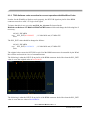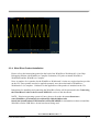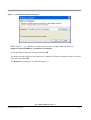
1
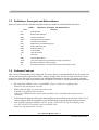
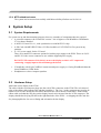
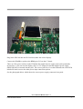
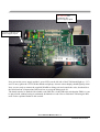
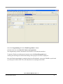
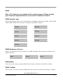
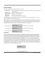
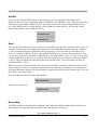
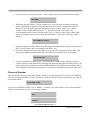
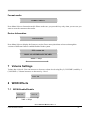
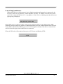
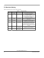
Freescale Semiconductor Document Number: MCF5251_TRIOUserManual Rev.1.5 User Guide 09/2007 MCF5251 TRIO User’s Manual 1 Introduction 1.1 Objective This document describes the use of the TRIO compressed audio player demo software on the Freescale Semiconductor M5251C3 EVB board. It describes how to set up the hardware, what additional hardware maybe required, how to boot the system and the software, and how to identify system issues. It also includes how to set-up the latest WindRiver tools (WorkBench) and how to flash the board with the WindRiver tools. 1.2 M5251C3 EVB Board Requirements The M5251C3 Rev 1.1 board is needed to run the demo software (audio/video mode). A colour QCIF format display (supplied) also needs to be attached to the board. An SD card formatted to FAT16 or FAT32 and containing MP3 files is also required to allow the audio playback demo to run. Contents 1 2 3 5 6 7 8 9 10 11 12 13 Introduction...........................................................1 System Setup..........................................................6 Flash Programming with WorkBench ..............47 Key Pad ................................................................52 Menu ....................................................................53 Volume Settings...................................................61 WOW Effects.......................................................61 Multiple Partitions and Multiple Devices .........64 Connecting to PC Through USB ...................65 Image/Video Related Changes.......................66 Play From Device ...........................................68 Revision History .............................................70 This document contains information on a new product. Specifications and information herein are subject to change without notice. © Motorola India Electronics Ltd., 2001, 2002, 2003, 2004, 2005. All rights reserved. © Freescale Semiconductor, Inc., 2006. All rights reserved. _______________________________________________________________________ 1.3 Definitions, Acronyms and Abbreviations Below are terms referenced in this document or that are needed to understand this document. Table 1. Definitions, Acronyms, and Abbreviations Term 1.4 Definition AD Audio Decoder BFM Buffer and File Manager DBB Dynamic Bass Boost GPIO General Purpose Input/Output ISR Interrupt Service Routine MP3 MPEG1 layer III and MPEG2 layer III MSC Master State Controller ROM Read Only Memory TBD To Be Decided TOC Table Of Contents UI User Input WMA Windows Media Audio JPEG Joint picture expert group (A standard for image compression) BMP Bit map (A standard for storing images) AVI Audio video interleave, a container format to store audio/video content Software Features This is a list of features that can be supported. The source demo s/w downloaded from the Freescale web site does not necessarily support these entire features straight of the box due to legal restrictions. Please contact your local Freescale representative for additional information or for any s/w feature upgrades. Features in italics are either not present in the web based s/w release or will be limited in their operation. • • • • MP3 playback (MPEG-1 Layer 3 and MPEG-2 Layer 3 with lower sampling rates) Limited to 30s playback for each file. WMA playback (high rate, mid rate and low rate). Limited to 30s playback for each file. Full function WMA decoder can be made available only to suitability Microsoft licensed customers. OGG Playback (Supports all bit rates and sampling rates specified by the encoder version 1.0 or earlier, supports both floor0 and floor1 spectral decoding, supports multiple logical streams) AAC Playback (Supports MPEG2-AAC LC profile, all bit rates (0-576), all sampling rates 8/11.025/12/16/22.05/24/32/44.1/48 except 64/88.2/96) Limited to 30s playback for each file. “Trio” HDD User Manual, Rev. 1.5 2 Freescale Semiconductor • • • • • • • • • • • • • • • • • • WAV file playback (16 or 8 bit linear samples; sampling rates supported as same as for MP3 and WMA) MP2 playback (MPEG-1 Layer 2 and MPEG-2 Layer 2). Real-time recording of input audio stream in MP3 format and storing it in the Hard disk. Encoder quality limited and record time limited to 30s. Real-time recording of input audio stream in ADPCM format (proprietary) and storing it in Hard disk as .adp file. Playback of files stored in ADPCM format. FAT32/FAT16 file system support. Multiple partition support. Multiple device support (Currently we support Hard disk HDD SD card, where SD card can be inserted and removed any time and USB Memory stick (via adaptor not supplied). Support for 3.5” HDD, 2.5” HDD, Compact Flash card, SD card, MMC card and USB Memory sticks Backup of data from SD card to Hard disk. USB 1.1 slave driver support, subsequent releases will also support USB 2.0 (HS and FS) USB MTP device driver support. Automatic device driver configuration (Mass storage/MTP) based on host OS. USB 1.1 host driver support, , subsequent releases will also support USB 2.0 (HS and FS) USB MTP host driver support. USB PlayFromDevice (non-DRM 1-wire and 2-wire) host driver support. File System related features ― Multi-task access. ― File related operations such as Open/Close/Seek/Create/Delete/Write ― Directory related operations such as Create Directory/Delete Directory/ Change Directory ― Data cache for file reading. ― Opening of multiple files at same time. ― Creation of multiple files at same time. ― Free space calculation ― Byte level access for reading files. ― Byte level access for reading and writing files. ― FAT32 and FAT16 Formatting of partition. ― Creation of a primary or secondary partition. Basic player controls ― Play/Pause/Stop ― Next track/Previous track ― Fast forward/Rewind ― Digital Volume Control Hierarchical file system browsing. “Trio” HDD User Manual, Rev. 1.5 Freescale Semiconductor 3 • • • • • • • • • • • • • • • • • • • • 1.5 Browsing through the directory structure and delete file/empty directories. Formatting media. Repeat (None / One / AB / Album) Preset 5-Band Graphical Equalizer (Flat / Rock / Classic / Jazz / Ultra bass modes) User Definable 5-Band Graphic Equalizer SRS effect, with controls for speaker type, WOW (width), TruBass and Brightness (focus). Intro-Scan Booting from Flash memory ID3 tags supported with artist, title, album, genre and year. WMA tags supported with artist and title only. Optional I2C interface support for UI/Display control from external chips. Alterate build option required to enable this feature. Clock switching to save power Switching the hard disk to low power mode, when not in use. Choice of encoder type (MP3 or ADPCM) Ability to decode and display JPEG compressed image Ability to decode and display BMP compressed image Slide show mode for image files Simultaneous decoding and display of image files without disturbing audio playback Ability to read and play MPEG4 simple profile video + MP3 audio stored in AVI file format. The maximum video frame size can be 220 * 176 where 220 is width and 176 is height of the video, the maximum video bit rate can be 128 kbps and maximum supported frame rate at that bit rate is 10 fps, assuming audio is 128 kbps 44.1 KHz). For simultaneous audio/video playback, audio sampling frequency should be 44.1 KHz. Note:- Depending on the Video bit rate frame rates of between 10~20fps are possible. Microsoft DRM 10 (Janus) protected WMA content transfer through MTP and playback. WMA and DRM libraries can only be provided to suitably Microsoft licensed customers, upon request via your Freescale representative. System Testing The system has gone through some basic system testing for various HDD, SD Card and USB Memory stick and FAT related test cases. The following sections will describe some categories of test cases. 1.5.1 Disk Related test cases 1. Read Single partition disk 2. Read Multiple Partition disk “Trio” HDD User Manual, Rev. 1.5 4 Freescale Semiconductor 3. 4. 5. 6. 7. 8. Read FAT32 file system created under Windows 2000 and Windows XP Read FAT32 file system created under Linux. Read FAT16 file system. Read 3.5” hard disks (from SeaGate, Maxtor) Read 2.5” hard disks (from Fujitsu, IBM) Read SD/MMC cards, which have FAT16 or FAT32 file systems and show them as another drive along with the partitions of HDD. 9. Compatible with Cornice discs and Compact Flash cards 10. The USB Host stack has been tested to be compatible with the following makes of USB memory sticks (thumb drives): SanDisk, Transcend 1.1, Transcend 2.0, JetFlash, PQI, Sony, Samsung, PNY Attache, Itek, Iomega, Trek, Lexar Jump. Various disk capacities like 32MB, 64MB, 128MB and 256MB, have been tested with the above makes. 512MB and 1G capacities have also been tested but not for all types listed above. 1.5.2 Directory Management related test cases 1. Read empty directory. 2. Read single-section directory (If a file/directory is stored in one single chunk of memory, they are referred as single section directory/file. If the file is split and stored in different chunks, they are referred as multiple section file/directory). 3. Read multiple section directory 4. Delete Single Section directory 5. Delete Multi Section directory 1.5.3 File Management related test cases 1. Read single section file 2. Read multiple section files 3. Open multiple files at the same time (currently two). 4. Read multiple files at the same time (currently two). 5. Create multiple files at the same time. 6. Delete single section file 7. Delete multi section file 8. Seek through a single section file 9. Seek through a multi-section file 10. Read data in bytes 11. Write data in bytes.. “Trio” HDD User Manual, Rev. 1.5 Freescale Semiconductor 5 1.5.4 MTP related test cases The system has been tested successfully with Microsoft PlaysForSure test kit 2.01.01. 2 System Setup 2.1 System Requirements For system set up and demonstration purposes, there are a number of components that are required. • • • • A personal computer with VisionClick version 7.9A or higher or with WindRiver WorkBench V2.4 or better installed. A M5251C3 board Ver 1.1, with a production version MCF5251 chip. A SD Card with MP3/JPEG/Video AVI files loaded in a FAT32/FAT16 file system in any partition. 8~ 12V power supply for the C3 board. There are a number of connector options for hooking up a supply to the EVM. These are J4, P1 and P2. P2 is the correct connector to use with the supplied power supply. DO NOT USE connector J14 which is next to the display as this is a 5V output and connecting a supply input to this will damage the board. • • 2.2 VisionProbe with 26 pin ColdFire® connector and power supply or if using WorkBench then the latest WindRiver (USB) Probe. Headphones or stereo computer speakers. Hardware Setup Attach the colour display to the EVM. The cable with the red connector plugs into the red (LCD2) connector on the EVM. The red coloured edge of the ribbon cable indicates the end that is number 1. The “key” on the connector may need to be broken off as on some boards the hole that it should locate with is blocked with solder. Then fold the ribbon cable such that the SIL plug on the display board can be inserted into the LCD1 connector. The display should then be lying flat and to the right hand-side of the EVM – overlapping the SD Card slot. See photograph below for correct fitting and orientation for the display. “Trio” HDD User Manual, Rev. 1.5 6 Freescale Semiconductor Plug in the SD Card into the SD Card slot (under the colour display). Connect the WindRiver probe to the BDM port (J12) on the C3 board. There are 2 DC power sockets on the EVM that the supplied power supply jack can be potentially inserted in to . The one near the display (J14) is a 5V output port and the supplied power supply SHOULD NOT be inserted into this jack. The correct jack to use is on the left hand side of the EVM labelled P2 and is next to the other power input connection options. See the photograph below which shows the correct power supply connector being used. “Trio” HDD User Manual, Rev. 1.5 Freescale Semiconductor 7 Do Not Use this connector for Power supply input Correct connector for Power supply input Now turn on the power supply and the 2 green LED’s on the left side of the EVM should light up – 3V3 and 5V ones, ignore the 1V2 LED this should not light up. Also the colour display should light up white. Now you are ready to connect the supplied WindRiver debug tool and compile the code, download it to the board and run it. Instructions follow on how to set up the debug tools etc. The board can also be flashed with suitable code (BIN file) via the WR tools such that the TRIO s/w can be played with without having to continually download exe code. How to flash the EVM using the WR tools is also explained further in this section. “Trio” HDD User Manual, Rev. 1.5 8 Freescale Semiconductor 2.3 Software / Debug Tool Setup 2.3.1 WindRiver WorkBench Set-up Instructions and TRIO Software Installation This section describes how to perform software development with the Freescale M5251C3 evaluation board with MCF5251 TRIO Evaluation Software using the Wind River Workbench 2.4, On-Chip-Debugging Edition with Wind River Compiler Evaluation, and Wind River Probe. This section includes the following topics: • • Freescale MCF5251 HDD Evaluation Software Installation. Wind River Product Installation. Launching Wind River Workbench. Creating the TRIO Software Project. Building the TRIO Software Project. Connecting the Wind River Probe to the Freescale M5251C3. Debugging the TRIO Software on the Freescale M5251C3. 2.3.2 Freescale MCF5251 HDD Evaluation Software Installation. The evaluation software needs to be downloaded from the following Freescale Semiconductor MCF5251 Web page. Access to this software for download is not instant as a request and approval must be sought first. The approval process may take between 1~3 working days. So its best to make this request in advance before proceeding further. The URL for the MCF5251 web page is :http://www.freescale.com/webapp/sps/site/prod_summary.jsp?code=MCF5251&srch=1 Then to access the link to the software download process scroll down the web page to "Software" "Application Software" - "Application Development Framework" and then click on the link which is named 5251_WRWB_TRIOSOFTWARERELx_x_x and then follow the online instructions. Note: The values for x in the links name may change from time to time. Once your request is approved you will receive a one time use URL via email from which to download the 5251_WRWB_TRIOSOFTWARERELx_x_x zip file. This zip file should then be extracted to a suitable location on your PC. It can be safely extracted to the root directory (C: or D: drive) as the extraction process will create its own unique folder location within the root for the TRIO software package. “Trio” HDD User Manual, Rev. 1.5 Freescale Semiconductor 9 2.3.3 TRIO Software code correction for correct operation with WindRiver Probe In order for the Wind River Probe to work properly, the PSTCLK signal on pin 24 of the BDM connector must be a valid 3.3V logic clock signal. To insure that this is true, go to the mcf5249_hw_init.asm file located in the HddSoftwareRelease6.3.2\HddCode\HddCodeHW\source folder and change the following line if necessary: #if (AP || PICARD) .equ PLL_INIT,0x13419025 #else ; 11.2896 MHz xtal, 97 MHz CPU The PLL_INIT value should be changed as follows: #if (AP || PICARD) .equ PLL_INIT,0x12434039 #else ; 11.2896 MHz xtal, 97 MHz CPU The original value causes the PSTCLK on pin 24 of the BDM connector to be unusable by the Wind River Probe and results in a loss of communications. The following is what the PSTCLK on pin 24 of the BDM connector looks like when the PLL_INIT value is set to the original value of 0x13419025: The following is what the PSTCLK on pin 24 of the BDM connector looks like when the PLL_INIT value is set to the new value of 0x12434039: “Trio” HDD User Manual, Rev. 1.5 10 Freescale Semiconductor 2.3.4 Wind River Product Installation Please refer to the instructions printed on the back of the Wind River Workbench 2.4, On-ChipDebugging Edition with Wind River Compiler Evaluation, CD jacket to install Wind River Workbench and the Wind River Compiler. Note: A number of s/w patches for the Wind River Workbench 2.4 suite are required and are provide on the CD. These patches need to be applied separately once the main install of Wind River Workbench 2.4 is complete. Guidance for the application of the patches is included on the CD. Instructions for installing and connecting the Wind River Probe will be presented in the Connecting the Wind River Probe to the Freescale M5251C3 section of this document. NOTE - If the host operating system is Linux, please refer to the document /home/username/WindRiver_Evaluation2.4/workbench-2.4/dfw/0128/host/x86linux2/bin/visionProducts/USBLinuxDriverFiles/README for information on how to install the Wind River Probe USB Driver for the host kernel being used. “Trio” HDD User Manual, Rev. 1.5 Freescale Semiconductor 11 2.3.5 Launching Wind River Workbench Launch Wind River Workbench using the method for your host operating system. (a) Linux Run the command: /home/user-name/WindRiver_Evaluation2.4/startWorkbench.sh. (b) Windows Select Start->Programs->Wind River->Wind River Workbench 2.4 Evaluation ->Wind River Workbench 2.4. Wind River Workbench launches and displays the revision, as shown in Figure 1 - 1. Figure 1 - 1 Workbench Revision Banner After the Java Virtual Machine has started and Wind River Workbench is loaded, the Workspace Launcher dialog box appears, as shown in Figure 1 - 2. “Trio” HDD User Manual, Rev. 1.5 12 Freescale Semiconductor Figure 1 - 2 Workspace Launcher Dialog Box NOTE: Figure 1 - 2 is a Windows example. On Linux, the workspace path will default to /home/user-name/WindRiver_Evaluation2.4/workspace. Accept the default workspace location and select OK. A warning message dialog box may appear as a reminder of when the evaluation license will expire. Take notice and click OK. The Welcome screen appears, as shown in Figure 1 - 3. “Trio” HDD User Manual, Rev. 1.5 Freescale Semiconductor 13 Figure 1 - 3 Welcome Screen Click Start. The Start Options screen appears, as shown in Figure 1 - 4. “Trio” HDD User Manual, Rev. 1.5 14 Freescale Semiconductor Figure 1 - 4 Start Options Screen 2.3.5.1 Importing the existing HDD Software Project Click Workbench. The Application Development perspective appears, as shown in Figure 1 - 5. “Trio” HDD User Manual, Rev. 1.5 Freescale Semiconductor 15 Figure 1 - 5 Application Development perspective Select File on the top left corner of Workbench tool bar and then select Import from the drop down menu. The Import: Select dialog box appears, as shown in Figure 1 - 6. “Trio” HDD User Manual, Rev. 1.5 16 Freescale Semiconductor Figure 1 - 6 Import: Select Dialog Box Select Existing Projects into Workspace as the import source. Click Next >. The Import: Import Projects dialog box appears, as shown in Figure 1 - 7. “Trio” HDD User Manual, Rev. 1.5 Freescale Semiconductor 17 Figure 1 - 7 Import: Import Projects Dialog Box Browse to C:\HddSoftwareRelease6.3.2\HddCode for the root directory. The project HDD_V6.3.2 appears under Projects. Please note that the top-level directory name will change as Freescale releases new software revisions. Click Finish. Workbench imports the HDD_V6.3.2 project in the default workspace folder and updates the Application Development perspective, as shown in “Trio” HDD User Manual, Rev. 1.5 18 Freescale Semiconductor Figure 1 - 8. “Trio” HDD User Manual, Rev. 1.5 Freescale Semiconductor 19 Figure 1 - 8 Updated Application Development Perspective Expand the HDD_V6.3.2 project folder and the Build sub-folder in the Project Navigator view. The Project Navigator will now display the project build targets in blue, as shown in Figure 1 - 9. “Trio” HDD User Manual, Rev. 1.5 20 Freescale Semiconductor Figure 1 - 9 Project Build Targets Freescale has predefined several project build targets. Currently, these are AP, APFLASH, APVIDEO, APVIDEOFLASH, and clean. Please note: that APVIDEO is the build option that should be used here. The AP and APFLASH build options should be ignored if present. The APVIDEOFLASH build produces a BIN file that can subsequently be used to program the Flash on the EVM. So for the purposes of this section we are only dealing with the APVIDEO build option and the clean option. 2.3.5.2 Building the HDD Software Project The project is now ready to build. First clean the project by highlighting the clean build target, right clicking, and selecting Build Target from the drop down menu that appears. The Build Console view will display the results of the build, as shown in Figure 1 - 10. “Trio” HDD User Manual, Rev. 1.5 Freescale Semiconductor 21 Figure 1 - 10 Build Console View for “clean” Build Target Now, build the target desired. For a target that can be downloaded to the Freescale M5251C3 evaluation board using the Wind River Probe, build the AP target by highlighting the AP build target, right clicking, and selecting Build Target from the drop down menu that appears. A number of warnings will be highlighted and displayed in the Build Console view. These can be safely ignored. The Build Console view output will be displayed, as shown in Figure 1 - 11. “Trio” HDD User Manual, Rev. 1.5 22 Freescale Semiconductor Figure 1 - 11 Build Console View for “AP” Build Target 2.3.5.3 Connecting the Wind River Probe to the Freescale M5251C3 Make sure the power to the Freescale M5251C3 is off. Please leave the power off until instructed to apply power later in this section. Detach the ColdFire 26-pin target-specific adapter from the Wind River Probe coaxial cable. Insert the target-specific adapter into the 26-pin keyed BDM header on the Freescale M5251C3. Attach the coaxial cable connector to the target-specific adapter. The connector and target-specific adapter are keyed to prevent an invalid connection. Plug the Wind River Probe into a USB port of the host system, if this has not already been done. The power/activity LED should light steady green. NOTE – For more information on setting up the Wind River Probe hardware, please refer to chapter 2 of the Wind River Workbench OCD Probe Hardware Guide. This document is located in the doc’s folder of the Wind River Workbench 2.4, On-Chip-Debugging Edition with Wind River Compiler Evaluation, CD. “Trio” HDD User Manual, Rev. 1.5 Freescale Semiconductor 23 A Workbench connection to the Wind River Probe will now be created. In the Target Manager view, click on the Create a New Target Connection icon. This icon is located just under the Target Manager tab to the far left side of all the other icons. The New Connection: Connection Type dialog box will appear, as shown in Figure 1 - 12. Figure 1 - 12 New Connection: Connection Type Dialog Box Select Wind River Probe. Click Next >. The New Connection: Wind River Probe Settings dialog box will appear, as shown in Figure 1 13. “Trio” HDD User Manual, Rev. 1.5 24 Freescale Semiconductor Figure 1 - 13 New Connection: Wind River Probe Settings The serial number for the Wind River Probe should appear in the USB Device Name field. If it does not appear, please refer to chapter 4 of the Wind River Workbench OCD Probe Hardware Guide located in the “docs” folder of the Wind River Workbench 2.4, On-Chip-Debugging Edition with Wind River Compiler Evaluation, CD. Click Select. The Processor Selection: Current Connection - Wind River Probe dialog box will appear, as shown in Figure 1 - 14. “Trio” HDD User Manual, Rev. 1.5 Freescale Semiconductor 25 Figure 1 - 14 Processor Selection: Current Connection - Wind River Probe Dialog Box Expand MCF52XX and select MCF5251. Click OK. Back at the New Connection: Wind River Probe Settings dialog box, click Next >. The New Connection: Target Operating System Settings dialog box will be appear, as shown in Figure 1 - 15. “Trio” HDD User Manual, Rev. 1.5 26 Freescale Semiconductor Figure 1 - 15 New Connection: Target Operating System Settings Dialog Box Click Next >. The New Connection: Object Path Mappings dialog box will be appear, as shown in Figure 1 - 16. “Trio” HDD User Manual, Rev. 1.5 Freescale Semiconductor 27 Figure 1 - 16 New Connection: Object Path Mappings Dialog Box Click Next >. The New Connection: Target State Refresh dialog box will appear, as shown in Figure 1 - 17. “Trio” HDD User Manual, Rev. 1.5 28 Freescale Semiconductor Figure 1 - 17 Nee Connection: Target State Refresh Dialog Box Click Next >. The New Connection: Connection Summary dialog box will appear, as shown in Figure 1 - 18. “Trio” HDD User Manual, Rev. 1.5 Freescale Semiconductor 29 Figure 1 - 18 New Connection: Connection Summary Dialog Box Click Finish. Workbench will now open a connection to the Wind River Probe in the Target Manager view, as shown in Figure 1 - 19. “Trio” HDD User Manual, Rev. 1.5 30 Freescale Semiconductor Figure 1 - 19 Target Manager View with Wind River Probe Connection In the Target Manager view, left click on the MCF5251 [connected] (indeterminate) line to highlight it. With the MCF5251 [connected] (indeterminate) line highlighted, right click and select Attach to Core from the drop down menu that appears. The Device Debug perspective will now be displayed, as shown in Figure 1 - 20. NOTE – For more information on establishing communications with the Wind River Probe, please refer to chapter 3 of the Wind River Workbench OCD Probe Hardware Guide. This document is located in the doc’s folder of the Wind River Workbench 2.4, On-Chip-Debugging Edition with Wind River Compiler Evaluation, CD. “Trio” HDD User Manual, Rev. 1.5 Freescale Semiconductor 31 Figure 1 - 20 Device Debug Perspective Open the OCD Command Shell view by selecting Window->Show View->OCD Command Shell. The OCD Command Shell view should show the ERR> prompt, as shown in Figure 1 - 21. “Trio” HDD User Manual, Rev. 1.5 32 Freescale Semiconductor Figure 1 - 21 OCD Command Shell View Click the Settings icon on the far right end of the OCD Command Shell view. It appears as a yellow box just to the right of the magnifying glass icon. The OCD Command Shell Settings dialog box will appear, as shown in Figure 1 - 22. Figure 1 - 22 OCD Command Shell Settings Dialog Box “Trio” HDD User Manual, Rev. 1.5 Freescale Semiconductor 33 Click Browse for the Playback File selection. Browse to locate the M5152C3.reg file. This file may not be present in the s/w release as shown below. But will be available as a separate download from the Freescale web page that the s/w release was obtained. This file contains the default register settings that will be used by the Wind River Probe to initialize the MCF5251 on the Freescale M5251C3. The Open dialog box should appear as shown in Figure 1 - 23. Figure 1 - 23 Open Dialog Box The OCD Command Shell Settings dialog box should now appear as shown in Figure 1 - 24. “Trio” HDD User Manual, Rev. 1.5 34 Freescale Semiconductor Figure 1 - 24 Updated OCD Command Shell Dialog Box Click OK. Click the Playback File icon on the far left end of the OCD Command Shell view. It appears as a black triangle pointing to the right. The M5251C3 register file will be loaded into the Wind River Probe. This step only needs to be performed the first time a new Wind River Probe connection is created in the Workbench Target Manager view. After the playback of the M5251C3 register file is completed, the OCD Command Shell view will appear as shown in Figure 1 - 25. “Trio” HDD User Manual, Rev. 1.5 Freescale Semiconductor 35 Figure 1 - 25 OCD Command Shell View After M5251C3 Register File Playback NOTE - For more information on configuring target registers, please refer to chapter 7 of the Wind River Workbench On-Chip Debugging Guide. The document is located in the doc’s folder of the Wind River Workbench 2.4, On-Chip-Debugging Edition with Wind River Compiler Evaluation, CD. Apply power to the Freescale M5251C3. The Target Exception dialog box will be displayed, as shown in Figure 1 - 26. This indicates that the Wind River Probe has detected a reset of the MCF5251 when power was applied to the Freescale M5251C3. “Trio” HDD User Manual, Rev. 1.5 36 Freescale Semiconductor Figure 1 - 26 Target Exception Dialog Box Click OK. The OCD Command Shell view should now show the BKM> prompt, as shown in Figure 1 - 27. If the ERR> prompt is still displayed, please enter the command IN at the ERR> prompt followed by the <Enter> key. NOTE - If the BKM> prompt is not displayed; please refer to chapter 4 of the Wind River Workbench OCD Probe Hardware Guide. This document is located in the doc’s folder of the Wind River Workbench 2.4, On-Chip-Debugging Edition with Wind River Compiler Evaluation, CD. NOTE – For more information on Wind River Probe low-level commands, please refer to the Wind River Workbench On-Chip Debugging Command Reference. This document is located in the doc’s folder of the Wind River Workbench 2.4, On-Chip-Debugging Edition with Wind River Compiler Evaluation, CD. “Trio” HDD User Manual, Rev. 1.5 Freescale Semiconductor 37 Figure 1 - 27 OCD Command Shell View with BKM> Prompt 2.3.5.4 Running and Debugging the TRIO Software on the Freescale M5251C3 The APVIDEO build target produces a file called hdd.elf. This file is will be downloaded to the M5251C3 using the Wind River Probe. To build the APVIDEO exe file, right-click on the APVIDEO in the Project Navigator Window and select “Build Target”. Once the build is complete a hdd.elf file will appear in the Project Navigator Window. Click the OCD Reset and Download icon in the Target Manager view. The icon is the fourth from the left and appears as a clockwise red arrow. The Reset & Download: Reset dialog box will appear, as shown in Figure 1 - 28. “Trio” HDD User Manual, Rev. 1.5 38 Freescale Semiconductor Figure 1 - 28 Reset & Download: Reset Dialog Box Click the Download tab. The Reset & Download: Download dialog box will appear, as shown in Figure 1 - 29. “Trio” HDD User Manual, Rev. 1.5 Freescale Semiconductor 39 Figure 1 - 29 Reset & Download: Download Dialog Box Click Add Files. When the Open dialog box appears, browse and select the hdd.elf file in the Build folder of the HDD_V6.3.2 project, as shown in Figure 1 - 30. “Trio” HDD User Manual, Rev. 1.5 40 Freescale Semiconductor Figure 1 - 30 Open Dialog Box Click Open. The Reset & Download: Download dialog box with be updated to show the hdd.elf file Download and Load Symbols boxes checked, as shown in Figure 1 - 31. “Trio” HDD User Manual, Rev. 1.5 Freescale Semiconductor 41 Figure 1 - 31 Reset & Download: Download Dialog Box Updated Click Reset and Download. The Reset & Download: Status dialog box will appear, as shown in Figure 1 - 32. The status will be displayed as the reset and download progresses. The entire process will take approximately 20 seconds to complete. “Trio” HDD User Manual, Rev. 1.5 42 Freescale Semiconductor Figure 1 - 32 Reset & Download: Status Dialog Box Click Close. The Save Changes dialog box will appear, as shown in Figure 1 - 33. Figure 1 - 33 Save Changes Dialog Box Click Yes. NOTE - For more information on using the Reset and Download view, please refer to chapter 7 of the Wind River Workbench On-Chip Debugging Guide. This document is located in the doc’s folder of the Wind River Workbench 2.4, On-Chip-Debugging Edition with Wind River Compiler Evaluation, CD. “Trio” HDD User Manual, Rev. 1.5 Freescale Semiconductor 43 Click the start() function displayed in the Debug view. The MCF5251 – WRProbe_MCF5251 System Context view will appear in the Workbench editor position, as shown in Figure 1 - 34. The MCF5251 Program Counter will be set to the instruction located at the start symbol. Figure 1 - 34 Debug View To run the code and to allow you to play back content on the SD Card, highlight the System Context line in the Debug view. Click the Resume icon in the Debug view. This icon is on the far left side and appears as a green triangle pointing to the right. The code should now be running and the colour display on the EVM will turn mostly blue, with some text display on the top row. Please refer to section.3. for the messages that will be displayed and how to then control the TRIO application that is now running. 2.3.5.5 How to set a breakpoint in WorkBench Open the Symbol Browser view by selecting Window->Show View-> Symbol Browser. “Trio” HDD User Manual, Rev. 1.5 44 Freescale Semiconductor Click on the Show the symbols loaded by the debugger icon in the Symbol Browser view. The icon appears as a bug on the far left of the Symbol Browser view. Enter OS_User in the Name Filter: box of the Symbol Browser view. Notice that the list of possible matching symbols is reduced as each new letter is entered. This is a feature of the Workbench code analysis features. Double click on the OS_UserInitPostConfig() entry with the round red function definition indicator icon to the left. The file main.c will be opened in the Workbench editor. The Device Debug perspective will be updated to appear as shown in Figure 1 - 35. Figure 1 - 35 Updated Device Debug Perspective Double click in gutter to the left of the line void OS_UserInitPostConfig(void) in the file main.c. This will plant a software breakpoint at the entry to function OS_UserInitPostConfig. Highlight the System Context line in the Debug view. Click the Resume icon in the Debug view. This icon is on the far left side and appears as a green triangle pointing to the right. “Trio” HDD User Manual, Rev. 1.5 Freescale Semiconductor 45 The TRIO software will execute until hitting the software breakpoint. The Device Debug perspective will be updated, as shown in Figure 1 - 36. Figure 1 - 36 Updated Device Debug Perspective After Software Breakpoint is hit Click the Resume icon in the Debug view to allow the HDD software to continue execution. The Suspend icon, to the immediate right of the Resume icon, can be used to halt the software at any time. “Trio” HDD User Manual, Rev. 1.5 46 Freescale Semiconductor 3 Flash Programming with WorkBench We need to build the BIN file and to do this we use the APVIDEOFLASH build option. Or any other valid “flash” type build option. Prior to doing a new build we first do a clean. Right click on the “clean” in the Project Navigator Window and select Build Target. The APVIDEOFLASH build target produces a file called hdd.bin. This is the file that will be used to program the Flash on the EVM using the Wind River Probe. To build the APVIDEOFLASH BIN file, right-click on the APVIDEOFLASH in the Project Navigator Window and select Build Target. Once the build is complete a new hdd.bin file will appear in the Project Navigator Window. Next connect the WindRiver probe to the EVM and power the board up. Connect the probe as previously instructed and attach to core. NOTE:In some cases it maybe necessary to unplug the colour LCD display completely from the EVM to allow Flash programming to complete successfully. Also to ensure correct Flash programming operation please ensure that BDM communication is set to CLK 4. To do this select the OCD Command Shell window. At he BKM prompt type CF CLK 4 and hit return. Your entry should look like dialog box below:- “Trio” HDD User Manual, Rev. 1.5 Freescale Semiconductor 47 Next select the Flash Programmer tab as shown below if the Flash Programmer tab is not available, Open the Flash Programmer view by selecting Window->Show View-> Flash Programmer. Then expand the Flash Programmer window to fill the screen. Select the Configuration tab within the Flash Programmer window and scroll down the Device Selection window to AMD, find the 29F160xB entry and expand it. Select and expand the, 1024 x 16 entry and finally select 1 Device. Set the RAM Workspace – Size box to 65372 this will maximize the flash programming speed). And click the Select All button at the bottom of the Sectors window and hit the return key on your keyboard. This selects all the sectors of the flash device to be erased. The dialog box should then look like the screen shot below. “Trio” HDD User Manual, Rev. 1.5 48 Freescale Semiconductor Now select the Add/Remove Files tab in the Flash Programmer window. Press the Add file button and navigate to the folder that now contains the new hdd.bin file. Once selected the window should look like the screen shot below. “Trio” HDD User Manual, Rev. 1.5 Freescale Semiconductor 49 “Trio” HDD User Manual, Rev. 1.5 50 Freescale Semiconductor Select the Programming tab in the Flash Programmer window. Click the check box for Send “IN” before each operation. The Programming window should now look like the screen shot shown above. To start the Flash erase and program sequence press the Erase/Program button. A dialog box showing the current status along with a progress bar will be displayed. Once the Flash programming is complete shut-down Workbench, remove the WindRiver probe and cycle the power on the EVM. The code should now be running on the EVM. “Trio” HDD User Manual, Rev. 1.5 Freescale Semiconductor 51 4 Startup When the system is started, the display may show different Status messages. If no SD Card is inserted in the SD card slot then it will display “NO MEDIA”. If no recognisable audio or video content is found on the SD Card it will display “NO MEDIA”. If media is present depending on the shows the message “RECOGNIZING DISC”. The display will be scrolling to the left. During this time, the system reads the Hard disk and gets the contents of the root directory. After reading the disc, it shows the first file/track, name/number. It plays by default the first song in the disc and shows the track/file being played. FILE1.MP3 5 Key Pad The keypad has 8 keys. Each of the keys is labeled on the board and has the following format. 3 6 2 5 8 1 4 7 Key 1 (REWIND / PREVIOUS TRACK) Key 2 (VOLUME- / MENU-) Key 3 (MENU CANCEL) Key 4 (STOP / MENU DOWN) Key 5 (MENU SELECT / MENU ITEM SELECT) Key 6 (PLAY/PAUSE/MENU_UP) Key 7 (FAST FORWARD / NEXT TRACK) Key 8 (VOLUME+ / MENU+) The keys are multiplexed and there action depends on the mode running. In normal mode the following keys are active: Table 2. Key Mappings in Normal Play Mode Keys Present Action Taken Key 1 (REWIND / PREVIOUS TRACK) Short press plays the previous track. Long press activates Rewind for as long as the key is pressed Key 2 (VOLUME- ) Digitally decreases the volume. Key 3 (CANCEL) No functionality Key 4 (STOP) Stop play. Key 5 (MENU SELECT ) Go into the main menu. Key 6 (PLAY/PAUSE) Short press alternates between Play and pause Key 7 (FAST FORWARD / NEXT TRACK) Short press plays the next track. Long press activates forward for as long as the key is pressed. “Trio” HDD User Manual, Rev. 1.5 52 Freescale Semiconductor Key 8 (VOLUME+) Digitally increase the volume. Table 3. Key Mappings When Menu is ON Keys Present Action Taken Key 1 (REWIND / PREVIOUS TRACK) No action. Key 2 (MENU-) Go from submenus to their parent menus. Key 3 (MENU CANCEL) Exit menu mode Key 4 (MENU DOWN) Navigate through current menu items. Key 5 (MENU ITEM SELECT) Select the currently displayed menu item. Key 6 (MENU UP) Navigate through the current menu item. Key 7 (FAST FORWARD / NEXT TRACK) No action. Key 8 (MENU+) Enter the sub-menu that is currently displayed (if the current entry has a sub-menu). 6 Menu The menu has the following sub options: 1. GRAPHICAL EQUALIZER SETTING 2. USER EQUALIZER SETTING 3. WOW SETTING 4. SPEAKER SETTING 5. BRIGHTNESS SETTING 6. SRS SETTING 7. TRUBASS SETTING 8. REPEAT SETTING 9. INTROSCAN 10. SHUFFLE 11. SEEK 12. FILE ERASE 13. SLIDE SHOW 14. RECORD 15. ENCODER TYPE 16. PLAYLIST 17. ID3 18. BACKUP DEVICE TWO 19. FORMAT MEDIA 20. DEVICE INFO “Trio” HDD User Manual, Rev. 1.5 Freescale Semiconductor 53 User can scroll through the various options using MENU-UP and MENU-DOWN keys in the order given above. Graphical Equalizer Settings This is a fixed Graphic Equalizer, with six settings: Flat, User Equalizer, Rock, Classic, Jazz and Ultra bass. These options can be viewed by using the Menu Plus & Menu Minus Keys. They can be selected using Menu select key. EQ: FLAT EQ: ROCK EQ: CLASSIC EQ: JAZZ EQ: ULTRA BASS Menu Plus/Menu Minus Keys User Equalizer Settings This is a variable (user configurable) graphic equalizer. The menu item has the following settings. It has 5 frequency bands: • • • • • 60 Hz 250 Hz 1000 Hz 4000 Hz 12000 Hz USER EQ: 60 HZ USER EQ: 250 HZ USER EQ: 1000 HZ USER EQ: 4000 HZ Menu Plus/Menu Minus keys Every band has separate amplitude levels ranging from 0 – 15. The user can browse through the bands using Menu +/- keys. A particular band is selected by pressing menu select key. After selecting the band, its present amplitude settings are displayed. The amplitude settings can be changed using the Menu +/- keys. The settings will not go below 0 or above 15. 60 HZ - 7 60 HZ – 8 60 HZ - 9 60 HZ - 10 Menu Plus/Menu Minus keys Amplitude level for the particular band is selected by pressing Menu Select key. User can come go back to the main display by pressing Menu cancel key. Presently there is no option for going back one level in the menu. “Trio” HDD User Manual, Rev. 1.5 54 Freescale Semiconductor WOW Note:- This feature is not enabled in the web s/w release. Please contact your Freescale representative for access to this feature if desired. WOW Speaker Type Nine different Speaker types can be selected (They are Headphone, 40Hz, 60Hz, 100Hz, 150Hz, 200Hz, 250Hz, 300Hz, 400Hz). This selection is valid only when WOW is enabled. SPK-HP SPK-200 SPK-40 SPK-250 SPK-60 SPK-300 SPK-100 SPK-400 SPK-150 WOW Brightness (Focus) Three levels of brightness can be selected (Low, Middle and High). This selection is valid only when WOW is enabled. BRI-L BRI-M BRI-L SRS (Width) Eleven levels 0-10 can be selected for SRS. This selection is valid only when WOW is enabled. WOW TruBass Eleven levels 0-10 can be selected for TRUBASS. This selection is valid only when WOW is enabled. “Trio” HDD User Manual, Rev. 1.5 Freescale Semiconductor 55 Repeat Settings This is the sixth menu item. Presently it has five settings: Repeat None Repeat All Repeat Album Repeat One Repeat AB This is the default setting and all tracks are played in order. Player stops at the end of the last song. Repeat all of the files in the disc. Repeat the current directory Repeat the current file/track. Repeat a portion of the current file/track. The repeat setting can be set by Menu select key. They can be browsed using the Menu +/- keys. This option is applicable to the present play setting. Repeat AB mode is set by pressing Menu Select key 2 times in the Repeat AB option of Menu. First key press sets position A in the current playing track, second key press sets the position B. The player loops around playing between the A and B position of the current file. Third Menu select key press disables the mode. This mode is only valid for a single track and in Pause or Play states. Menu Select Key REPEAT AB Set position A in current track Menu Select Key REPEAT AB Set position B in current track Menu Select Key Cancel Repeat AB REPEAT AB Introscan User can select this menu item by pressing Key 5 (Menu Select). When this menu item is selected, all the tracks in the CD are played for 10 seconds in an order determined by the Repeat and the Shuffle setting. If the software is already in repeat or shuffle mode, the introscan will play the first 10 seconds of the songs in the order determined by the repeat or the shuffle. Once introscan is selected, the keypad exits the menu mode and continues displaying “INTROSCAN”. User can come out of the introscan mode by pressing PLAY, by which the currently playing song will come out of the introscan mode and will be played fully, display also changes from INTROSCAN to display the file/track currently playing. Introscan mode is reset when STOP key is pressed. Introscan mode starts scanning with the first song according to the present play settings, eg. If a directory is played then introscan will start scanning songs from the first file in the current playing directory. INTROSCAN “Trio” HDD User Manual, Rev. 1.5 56 Freescale Semiconductor Shuffle User can select the SHUFFLE option. In this menu item, the current SHUFFLE setting will be displayed. There are only two possible options (SHUFFLE_ON, SHUFFLE_OFF). The user can see the other option by pressing the Menu Plus key. Any option can be selected by pressing the Menu Select key. If the shuffle mode is on, then shuffle is done within the current directory. If a playlist is being played, then shuffle is done within the Playlist. SHUFFLE OFF SHUFFLE ON Seek This sub-menu will allow the user to search for a track/folder in the directory structure or disc. User can enter the root directory by scrolling to Seek menu item in the Main Menu and pressing Key 8 (MENU +). This will display the first track/folder in the root directory or first file in the first sub-directory or disc. User can press (MENU UP) Key 1 and (MENU DOWN) key 2 to browse the root directory. User can exit the root directory and return to Main Menu by selecting (MENU -) Key 2. If user wants to enter a folder within the root directory, he scrolls down to that folder in the root directory and selects (MENU +) Key 6. This will display the first track/folder in the chosen folder. User can exit this sub folder by selecting (MENU -) Key 2. When user chooses a track/file/folder, the selected track/file/folder (all songs within that folder) will be played. When user selects a song from a particular directory then the play setting is set to that directory and repeat and shuffle settings will be applicable to songs present in the present directory only. User can also choose a directory to play. Files are displayed with their names and extension. FILENAME.EXT Directories are shown as: >DIRECTORY Recording The HDD system has an option of recording any audio input into an MP3/ADPCM file and store it in the hard disk. The steps that have to be taken to use this option are as follows: “Trio” HDD User Manual, Rev. 1.5 Freescale Semiconductor 57 1. Choose the menu using the menu key. The recording option is the sixth item in the menu. RECORD 2. When this option is chosen, a check is made to see if the file system contains a directory named “RECORD” in the root. If the directory does not exist, it is created first. Once the directory is present, a file with name MUSICxxx.mp3 is created, where “xxx” equals “number of files in RECORD directory + 1”. If the file already exists, then “xxx” is incremented until we find a valid file name. For e.g. if there are three files in RECORD directory, then the system creates a file “MUSIC004.mp3”. Once this is done the system displays: RECORDING MODE 3. Upon this, the user should connect the audio input to the audio input ports that are present on the C3 board. Then to start recording press the PLAY key. 4. Once the recording starts, the song, which is being recorded is played out on the DAC. The system also displays the name of the file onto which the recorded song is being stored. MUSIC003.mp3 5. To stop recording Press the stop key. The system then completes the recording of the file system. It then re-reads the directory structure and starts playing again from the first file. The newly created file would be present in the RECORD directory and the user should be able to select and play it through the seek option / or by going to it through next/previous track keys. Choice of Encoder The user has the option to record either in MP3 format or in ADPCM format. It is good to use ADPCM for voice recording and MP3 for audio. The menu provides an option to choose the encoder we want. Go to the menu option ENCODER TYPE If you press the MENU SELECT key or MENU + key then you will be able to see the current encoder format. Use the Menu+ key to go to the desired format MP3 ADPCM “Trio” HDD User Manual, Rev. 1.5 58 Freescale Semiconductor Press the MENU SELECT key to select your desired encoder type. It is not necessary to select the encoder type every time we have to record. Once the encoder type is selected, all the future recordings will be of the same encoder until we change the encoder type specifically. Playlist The “PLAYLIST” option in main menu is for playing playlist files present in the Hard Disk. The Playlist option is the 7th item in the main menu. The system supports, the .rmp playlist files (Created using Real Audio Player).pls and .m3u playlist files.(Created by Winamp). User can go in to the playlist menu by pressing Menu+ in Playlist option of the main menu. PLAY LIST Browsing through the playlist The system displays all the playlist files (.m3u or .pls or .rmp) in the Hard Disk. Presently, it supports playlist files within the current directory. User can scroll through the playlist files using Menu Up/Down keys. The system currently does not read all the playlists upfront. Rather it reads the playlists which are present in each directory, as and when the user enters a new directory. Menu Up/Down PLAYLIST1.RMP : : PLAYLIST2.RMP User can see the content of a particular playlist file by pressing Menu+ in the corresponding playlist file entry. The display shows the first song file in the playlist. User can scroll through the songs in playlist using the Menu Up/down keys. User can come back to the playlist menu by pressing Menu- key. Playlist selection User can select a playlist file (.m3u or .pls) to play by pressing Menu Select key. System will play all the files of the selected playlist. User can also play a particular song file from the playlist. After selecting a particular file to play, only the files in the particular playlist will be played. Now the play setting is set to playlist, shuffle and repeat will be valid only for the files currently in the playlist file. The Playlist is automatically cancelled, when the user selects another song to play through the seek functionality. The playlists can also be played by selecting them through the normal seek menu. “Trio” HDD User Manual, Rev. 1.5 Freescale Semiconductor 59 File Erase File erase option in the main menu is for the user to select the file to be deleted in the hard disk. User can select directory or file to delete. The file or the directory to be deleted can be in any of the directories present in the hard disk. Before selecting, the user should stop playing the current file and go in to erase mode. In erase mode the user can search for the file to be deleted as in seek mode. To select the file after going to file erase mode refer to Seek. It does not delete directories, with valid files to play. If the user selects such directory to delete, it displays DIRECTORY NOT EMPTY. From here the user can change the mode through menu. ID3 Tags Trio supports ID3 version 2.3 and version 1.0. User can enter the Id3 sub menu by pressing MENU+ key in ID3 main menu option. It Parses mp3 files to get basic information about the file like Album name, Artist, Genre etc. Presently supports following fields: • • • • • Album Name Title of song Artist Name Genre Year If there are no tags in the file then only the file name is displayed. Otherwise, all the fields are concatenated and displayed with “-“ as a field separator. The whole display keeps scrolling. ALBUM1 – TITLE1 – PETER- POP- 2002 Backup of Device Two Trio supports copying the entire directory structure of the second device (SD card in our case) into the HDD. A new directory “backxxx’ is created in the root directory of the first partition of the hard disk and the entire contents of SD card is copied into that. While the copying is going on, the system will be displaying, COPYING DEVICE TWO Once the backup is complete the system then displays STOP. “Trio” HDD User Manual, Rev. 1.5 60 Freescale Semiconductor Format media FORMAT MEDIA Press Menu Select to format the media. Please make sure you press this key only when you are sure you want to erase the content on the media. Device Information DEVICE INFO Press Menu Select to display the firmware version. Press menu plus/minus to browse through the versions of different features enabled/disabled in the system. F/W version: 6.6 Build: AP/APVIDEO/APUPICARD Menu +/- Keys 7 Volume Settings Volume has 64 levels. User can increase or decrease volume levels using Key 2 (VOLUME-) and Key 8 (VOLUME+). Volume increases or decreases by 1 level. VOL - 50 8 WOW Effects 7.1 WOW Enable/Disable WOW: OFF WOW: ON VOL +/- Keys “Trio” HDD User Manual, Rev. 1.5 Freescale Semiconductor 61 1. Press Menu Select Key (Key 5) to enter the main menu 2. Press menu down key (STOP key, i.e. key 4)/Up key (PLAY/PAUSE key, i.e. key 6) until SRS is displayed. 3. Then press VOL+/VOL- key (i.e. key 2/key 8) to enable/disable SRS (i.e. SRS ON/ SRS OFF will be displayed) 4. Then press the Menu select key to enable or disable SRS 7.2 WOW Settings There are four different SRS settings and they can be selected using Menu Up/Down Keys as shown below. SPK: HP BRI: H Menu Up/Down Keys TRUBS: 6 SRS: 8 a. SPEAKER TYPE – There are 9 different speakers types that can be selected. A Particular Speaker type can be selected by following the steps given below 1) Press Menu Select Key (Key 5) to enter the main menu. 2) Press menu Up/Down Key until SPK: HP is displayed as shown above. The default speaker type is headphone. 3) Press VOL+ Key to move from Speaker type “HP” to “400” HZ and Press VOLKey to move from Speaker type “400” HZ to “HP” The following are the different speaker types "HP", "40HZ", "60HZ", "100HZ", "150HZ ", "200HZ ", “Trio” HDD User Manual, Rev. 1.5 62 Freescale Semiconductor "250HZ ", "300HZ ", "400HZ” SPK: HP SPK: 40 SPK: 60 SPK: 100 SPK: 150 SPK: 200 SPK: 250 SPK: 300 SPK: 400 Vol + Key Vol - Key b. BRIGHTNESS – This has 3 options. Low Medium and High. A Particular brightness can be selected by following the steps given below. 1) Press Menu Select Key (Key 5) to enter the main menu 2) Press menu Up/Down key until BRI: H is displayed as shown above. The default brightness is High. BRI: L BRI: M BRI: H Vol + Key Vol - Key 3) Press VOL- key to move from H to L and VOL+ key to move from L to H. c. BASS CONTROL – This is the control for True Bass in SRS. This can be varied from 0 to 10. TruBass can be varied by using the following steps: 1) Press Menu Select Key (Key 5) to enter the main menu 2) Press menu Up/Down key until TRUBS: 6 is displayed as shown above. The default True Bass value is 6. TRUBS: 0 TRUBS: 10 Vol + Key Vol - Key 3) Press VOL+ Key to move from 0 to 10 and VOL- key to move from 10 to 0. “Trio” HDD User Manual, Rev. 1.5 Freescale Semiconductor 63 d. SRS CONTROL – This is the control for WOW in SRS. This can be varied from 0 to 10. SRS Width can be varied by using the following steps: 1) Press Menu Select Key (Key 5) to enter the main menu 2) Press menu Up/Down key until WOW: 8 is displayed as shown below. SRS: 0 SRS: 10 Vol + Key Vol - Key 3) Press VOL+ Key to move from 0 to 10 and VOL- key to move from 10 to 0. Note: If you are already in the main menu then, Menu Up/Down keys can be used to browse through different SRS settings. 9 Multiple Partitions and Multiple Devices If the hard disk contains more than one partition, the Trio HDD system reads all the valid partitions that have FAT32/FAT16 file systems. If the disk has 4 partitions, then these partitions are named as Partition 1, Partition 2, Partition 3 and Partition 4. In case of the HDD containing more than one partition, when the user enters the Seek Menu to browse through the directory, the system displays the first partitions in which we want to enter. PARTITION 1 PARTITION 2 If the HDD has only one partition then when the user enters the Seek option, the contents of the root directory are directly displayed. The Trio HDD system allows connection of other removable devices like SD/MMC card to the system. These can be inserted either before powering the system or while the system is playing. As soon as the system detects that the SD/MMC card is inserted, it reads the file system on the SD/MMC card and adds it as another partition on the disk. The user can then use the seek menu option to browse through the contents of the disk. “Trio” HDD User Manual, Rev. 1.5 64 Freescale Semiconductor 10 Connecting to PC Through USB The Trio HDD system allows the user to connect to PC through USB. Depending on the Operating system running on the PC, to which the device is connected to, Mass storage device or MTP device driver will be configured at runtime. In the Mass storage mode as soon as the USB cable is plugged on to the device, the system stops playing and then displays. USB CONNECTED In case of MTP device, the system remains in the same state as it was before the USB cable plug-in. So, playback is not stopped in this case. The default driver of the device is MTP. If the PC has Windows XP operating system with Windows media player 10 installed, then the device is recognized as a MTP device else Mass storage device. Mass storage device When configured as a Mass storage device, the PC displays the device HDD as another drive. Then the user can do the normal operations like transferring files to/from the disk, formatting the disk, deleting files, etc. Basically the user can treat the HDD as another drive. Once the user finishes his operations on the PC, then he/she should disconnect the USB drive properly before plugging out the USB cable. Once this happens, the system automatically starts playing again from the root directory. Currently the Trio HDD system connects only the HDD to the PC through USB. Even if the SD/MMC card is inserted in the system, it does not show up on the PC as another drive. Media transfer protocol (MTP) device “Trio” HDD User Manual, Rev. 1.5 Freescale Semiconductor 65 After device is detected as a MTP device, start WMP if not running already. In WMP, click on the “Sync” tab and go to device synchronization feature. Once the device is detected as an MTP device, WMP will show the following dialog box, asking for sync option. This dialog can be ignored by clicking on the “Cancel” button. The WMP window will show the file/folders on the device as shown below. File transfer to the device can be done thorough the “sync” feature. The playlist to be synced can be selected form the upper left list box. Transfer or Sync starts when the “Start Sync” button is pressed. Sync list selection box. Device name. Current selected playlist to be synced Device content. 11 Image/Video Related Changes This section will describe the changes in HDD system user interface to accommodate Image decoding and display and for playback of video files. 10.1 Decoding and display of image files During normal audio/video playback, image files are skipped. For e.g. if we have file1.mp3, xyz.jpg and file2.mp3 files stored in sequence in the HDD then after playing file1.mp3, system will directly jump to file2.mp3 thus skipping xyz.jpg during continuous playback. “Trio” HDD User Manual, Rev. 1.5 66 Freescale Semiconductor Image can be decoded and displayed only in two modes: 1. Normal Image mode 2. Slide Show Mode When in image mode, only audio files are played. 10.1.1 Normal Image Mode To enter normal image mode, user should browse the files through seek menu and then select an image (jpeg/bmp) file. This will change the player mode to image mode. In image mode following key mapping will be applicable. Table 4. Key Mapping in Image Mode Keys Present Action Taken Key 1 (REWIND / PREVIOUS TRACK) Short press decodes and displays the previous image. Long press no functionality. Key 2 (VOLUME- ) No functionality Key 3 (CANCEL) Exit image mode Key 4 (STOP) No functionality Key 5 (MENU SELECT ) No functionality Key 6 (PLAY/PAUSE) No functionality Key 7 (FAST FORWARD / NEXT TRACK) Short press decodes and displays the next image. Long press no functionality. Key 8 (VOLUME+) No functionality If user exits the image mode by pressing image cancel mode then normal key mapping, as indicated in section 5 will be applicable. In case system encounter an error while decoding an image then it will display “Image Decode Error” on the LCD. User can then select some other image by pressing appropriate key (Previous Track/Next Track in this case). Please note that menu will not be enabled when image mode is on. 10.1.2 Slide Show Mode In slide show mode, the image files stored in the selected directory are decoded and displayed continuously. After decoding the last image, it again starts from first image in the directory. The directory can be selected through the menu. The images are decoded or displayed at a preset time (currently 5 sec) or after image decodes time, whichever is higher. E.g. if image decode time is 6 sec. then image will be displayed after 6 second. If image decode time is 3 second then image will be displayed after expiry of timer (5 seconds). In case there is error in image decoding then that image is automatically skipped without giving any indication of error to user. Key mapping as specified in section 5 are applicable in slide show mode. “Trio” HDD User Manual, Rev. 1.5 Freescale Semiconductor 67 Selecting Slide Show Mode 1. Select Slide Show mode item from the main menu. 2. Browse through the directory structure and select a directory or an image file in a directory 3. This will set the image mode to slideshow mode. The system will decode and display all the images in the directory. In case there are no image files in the selected directory then the system will display error message 10.2 Playback of video file Video file playback is similar to audio playback file. Instead of displaying file names as in audio file case, here the video frame is displayed on the LCD screen. During video playback, key mapping is changed slightly as indicated in the table below. Table 5. Key Mappings during Video Playback Keys Present Action Taken Key 1 (REWIND / PREVIOUS TRACK) Short press plays the previous track. Long press activates Rewind for as long as the key is pressed Key 2 (VOLUME- ) Digitally decreases the volume. Key 3 (CANCEL) No functionality Key 4 (STOP) Stop play. Key 5 (MENU SELECT ) No functionality Key 6 (PLAY/PAUSE) Short press alternates between Play and pause Key 7 (FAST FORWARD / NEXT TRACK) Short press plays the next track. Long press activates forward for as long as the key is pressed. Key 8 (VOLUME+) Digitally increase the volume. As indicated in the table, menu is disabled during video playback. 12 Play From Device When an MTP device is connected to the host it first checks the target device supports 1-wire PFD, else it checks if it supports 2-wire support and lastly if none of the options are available then it checks if it supports getPartialObject operation. 1-wire PlayFromDevice When an MTP device which supports 1-wire operations or supports getPartialObject, the current playback is stopped and the connected media file/directory information is read to search for a playable file. In 1-wire mode, menu items like Erase, Recording, Encoder type etc are disabled. “Trio” HDD User Manual, Rev. 1.5 68 Freescale Semiconductor 2-wire PlayFromDevice When an MTP device which supports 2-wire defined operations and properties is connected to the host port, read its the root directory, and the playback will stop. The display will reflect the system state of the connected USB device, i.e. stop, pause or if the device is in playing state then the current playing song is displayed. PFD_DEVICE_SONG.MP3 When MTP device is connected, all the menu options will be disabled except SEEK option. SEEK submenu will now display the contents of connected MTP device in the similar fashion it does for itself. Using SEEK submenu from MENU, user can search through the contents of the device connected and select a file/track to play from the MTP device connected. When the USB cable is disconnected host goes to STOP state and displays STOP. STOP “Trio” HDD User Manual, Rev. 1.5 Freescale Semiconductor 69 13 Revision History Table 6 summarizes the revisions to this document. Table 6. Revision History Version Date Revised By Description of Changes 0 5/2006 – First release of this document. 1 6/2006 G.Kwiecinski Updated from the AllGo TRIO HDD Manual. th Last review 15 March. Also added updates specifically for MCF5251 and added WindRiver Workbench set-up instructions from the QSG 1.1 6/2006 G.Kwiecinski Removed VisionClick / VisionProbe set-up guide section 1.2 109/2006 G.Kwiecinski 1.3 9/2006 G.Kwiecinski 1.4 10/2006 Ashutosh Srivastava 1.5 09/2007 Ashutosh Srivastava Added WB Flash programming guide and suggested improvements by WR Improved WB Flash programming guide, added additional steps for EVM set-up (including photographs). Added steps to download 5251 TRIO software from the FSL web site. Updated for the 5251 release 6.5 Updated for the 5251 release 6.6 “Trio” HDD User Manual, Rev. 1.5 70 Freescale Semiconductor Notes “Trio” HDD User Manual, Rev. 1.5 Freescale Semiconductor 71 How to Reach Us: Home Page: www.freescale.com E-mail: [email protected] USA/Europe or Locations Not Listed: Freescale Semiconductor Technical Information Center, CH370 1300 N. Alma School Road Chandler, Arizona 85224 +1-800-521-6274 or +1-480-768-2130 [email protected] Europe, Middle East, and Africa: Freescale Halbleiter Deutschland GmbH Technical Information Center Schatzbogen 7 81829 Muenchen, Germany +44 1296 380 456 (English) +46 8 52200080 (English) +49 89 92103 559 (German) +33 1 69 35 48 48 (French) [email protected] Japan: Freescale Semiconductor Japan Ltd. Headquarters ARCO Tower 15F 1-8-1, Shimo-Meguro, Meguro-ku, Tokyo 153-0064, Japan 0120 191014 or +81 3 5437 9125 [email protected] Asia/Pacific: Freescale Semiconductor Hong Kong Ltd. Technical Information Center 2 Dai King Street Tai Po Industrial Estate Tai Po, N.T., Hong Kong +800 2666 8080 [email protected] For Literature Requests Only: Freescale Semiconductor Literature Distribution Center P.O. Box 5405 Denver, Colorado 80217 1-800-441-2447 or 303-675-2140 Fax: 303-675-2150 [email protected] Information in this document is provided solely to enable system and software implementers to use Freescale Semiconductor products. There are no express or implied copyright licenses granted hereunder to design or fabricate any integrated circuits or integrated circuits based on the information in this document. Freescale Semiconductor reserves the right to make changes without further notice to any products herein. Freescale Semiconductor makes no warranty, representation or guarantee regarding the suitability of its products for any particular purpose, nor does Freescale Semiconductor assume any liability arising out of the application or use of any product or circuit, and specifically disclaims any and all liability, including without limitation consequential or incidental damages. “Typical” parameters that may be provided in Freescale Semiconductor data sheets and/or specifications can and do vary in different applications and actual performance may vary over time. All operating parameters, including “Typicals”, must be validated for each customer application by customer’s technical experts. Freescale Semiconductor does not convey any license under its patent rights nor the rights of others. Freescale Semiconductor products are not designed, intended, or authorized for use as components in systems intended for surgical implant into the body, or other applications intended to support or sustain life, or for any other application in which the failure of the Freescale Semiconductor product could create a situation where personal injury or death may occur. Should Buyer purchase or use Freescale Semiconductor products for any such unintended or unauthorized application, Buyer shall indemnify and hold Freescale Semiconductor and its officers, employees, subsidiaries, affiliates, and distributors harmless against all claims, costs, damages, and expenses, and reasonable attorney fees arising out of, directly or indirectly, any claim of personal injury or death associated with such unintended or unauthorized use, even if such claim alleges that Freescale Semiconductor was negligent regarding the design or manufacture of the part. Freescale™ and the Freescale logo are trademarks of Freescale Semiconductor, Inc. All other product or service names are the property of their respective owners. © Freescale Semiconductor, Inc. 2006. All rights reserved. HddUserManual Rev. 1.5 09 /2007 Document Number: MCF5251_TRIOUserManual