1
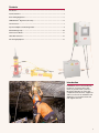
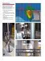
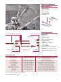
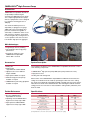
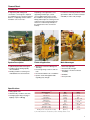
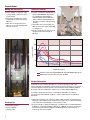
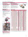
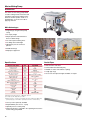
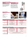
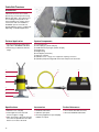
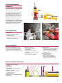
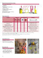
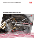
Service, Accessories and Equipment
2
Contents
Introduction .................................................................................................................. 3
Technical Service .......................................................................................................... 4
Rock Drilling Equipment ............................................................................................... 5
OMEGA-BOLT® High-Pressure Pump .......................................................................... 6
Cement Grout ............................................................................................................... 7
Injection Adapters and Flushing Heads........................................................................ 9
Mortar-Mixing Pump................................................................................................... 10
Flow-Pressure Meter................................................................................................... 11
Cable Bolt Tensioner................................................................................................... 12
Pull Testing Equipment ............................................................................................... 13
Introduction
DYWIDAG-Systems International (DSI)
provides its customers with a large
variety of ground control systems for
Mining and Tunneling as well as with
competent technical service, equipment
and accessories for the installation and
application of rock reinforcement and
rock support elements.
3
Technical Service
A DSI team of experienced technicians
and supervisors provides technical
support as well as on-site product
management. Our service team is
available for general and product-specific
questions in the following areas:
■■ Design, testing, and evaluation of
rock bolt systems
■■ Self-Drilling reinforcement technology
■■ Layout and optimization of lattice girder
support
■■ Pipe umbrella support and drainage
drilling works
■■ Accomplishment and monitoring of
injection works
■■ Testing of product usage properties
4
Rock Drilling Equipment
Fields of Application
■■ Blasthole drilling
■■ Production drilling
■■ Extension drilling
■■ Overburden drilling
■■ Pre-Drilling
System Components
Shank adapters
Extension drilling equipment
Drill bits in retrac design
■■ Shank adapters
Drill bits in flat face
■■ Couplings
■■ Adapter couplings
■■ Extension drilling equipment
■■ Coupling adapters
■■ Drill bits
■Drill bits in either flat face or
retrac design
■Cross drill bits
■■ Pre-Drilling bits for the AT-SYSTEM
Couplings
Adapter couplings
Coupling adapters
Cross drill bits
■■ Various adapters and driver tools for
rock bolts
■■ Individual drill bits available on request
Order Information
Article Description
Available Thread Types 2)
Shank adapters
R32, R38, R51, T32, T38, T51
Couplings
Coupling adapters F/F 1)
Extension rods M/F 1)
Extension rods M/M 1)
Adapter M/F 1)
Adapter M/M 1)
Button drill bits version flat face
Button drill bits version retrac
Cross drill bits
Pre drill bits
Driver tools
R32, R38, R51, T32, T38, T51
R32, R38, R51, T32, T38, T51
R32, R38, R51, T32, T38, T51
R32, R38, R51, T32, T38, T51
R32, R38, R51, T32, T38, T51
R32, R38, R51, T32, T38, T51
R32, R38, R51, T38, T51
R32, R38, R51, T38, T51
R32, R38, R51, T38, T51
R32, R38, R51, T38, T51
R32, R38
Required Information 3)
Thread (connecting thread type; version M or F),
rock drill type, length [mm] 1), 3)
Thread (connecting thread type)
Thread (connecting thread type A and B)
Thread (type connecting thread); length [mm] 3)
Thread (type connecting thread); length [mm] 3)
Thread (connecting thread type A and B)
Thread (connecting thread type A and B)
Thread (connecting thread type), drill bit diameter
Thread (connecting thread type), drill bit diameter
Thread (connecting thread type), drill bit diameter
Thread (type connecting thread), drill bit diameter
Rock bolt type, thread (type connecting thread)
1) ”F” ... female (inner) thread; ”M” ... male (outer) thread
2) Special thread types available on request
3) Special lengths available on request
5
OMEGA-BOLT® High-Pressure Pump
Introduction
OMEGA-BOLT® Expandable Rock Bolts
are preferably installed using the
electrical type 300E high-pressure pump.
This compact high-performance pump
with an 11 [kW] electric motor is designed
for a maximum working pressure of
300 [bar].
The maximum inflation pressure is
adjusted by a spring pressure gauge;
additionally, a pressure limiting valve
prevents overload. The regulation is
effected by a combination switch on/off
and emergency shutdown, respectively.
Protection against dry running ensures a
secure operation of the low-noise and
low-vibration high-pressure aggregate.
Main Advantages
■■ Tough design and easy handling
■■ Fast installation due to high pump
performance
■■ An optimum expansion of the
OMEGA-BOLT® Expandable
Friction Bolt is ensured
Accessories
System Description
■■ Setting arm
The installation equipment for the OMEGA-BOLT® Expandable Rock Bolt consists
of the following components:
■■ Setting head
■Type EFB-120 or EFB-160/240
■■ OMEGA-BOLT® high-pressure pump 300E (water pump and electric motor)
■■ High-pressure hoses in different
lengths available
■■ High-pressure hose
■■ Spare parts available on request
■■ Setting arm with setting head
■■ Alternative high-pressure pumps
available on request
■■ OMEGA-BOLT® pull testing equipment
available on request
Further References
■■ Brochure OMEGA-BOLT®
Expandable Friction Bolt
■■ Operating manual OMEGA-BOLT®
High-Pressure Pump Type 300E
■■ Spare parts list OMEGA-BOLT®
High-Pressure Pump Type 300E
After insertion of the OMEGA-BOLT® Expandable Rock Bolt into the borehole, the
setting arm is fitted to the bolt’s head. By operating the valve lever on the setting
arm, the bolt is hydraulically expanded (unfolded) using high-pressure water, which is
induced into the inside of the folded bolt tube. After reaching the defined maximum
setting pressure, the valve lever is released and the setting head is pulled away from
the bolt’s head.
Specifications
Characteristics
Dimensions (L x W x H)
Weight
Max. flow rate
Operating pressure 1)
Max. operating pressure
Power supply
Nominal power
Electrical connection
Pumping rotation speed
Unit
[mm]
[kg]
[l/min]
[bar]
[bar]
[V]
[kW]
[A]
[rpm]
1) Required tube connection 3/4", water connection pressure: 2 [bar]
6
Value
800 x 400 x 455
90
21
300
320
3 ~ 400
11
25
1,400
Cement Grout
Introduction
In engineering and underground
construction, cement grout is required
for establishing a force and form fit bond
between a supporting member and the
foundation soil or rock mass.
Depending on the application or the
supporting member type, cement
grout is applied either before or after
the installation using an injection hose.
Mixing and transport of cement grout are
carried out using mortar-mixing pumps,
which are constructed specifically for
the requirements in the construction
industry.
In contrast to customary products, cement
grout features both an excellent overhead
workability as well as early strength.
System Description
Fields of Application
Main Advantages
■■ Hydraulically bonded cement grout
■■ Grouting of rock bolts in Mining and
Tunneling
■■ Universally applicable
■■ Pressure grouting of anchors and soil
nails
■■ Thixotrope – excellent overhead
workability
■■ Portland cement with high quality
mineral additives
■■ Bonding medium for cement grout
embedded anchors and rock bolts
■■ Rock and foundation soil consolidation
■■ Injection works with high demands
regarding early strength
■■ Increased early strength
■■ Swellable
■■ Frost-proof XF3
Specifications
■■ Mixing liquid: water
■■ Shelf life in dry conditions: 6 months
■■ Packaging: paper bag of 25 [kg] or
bigbags of up to 1,000 [kg]
Characteristics 1)
Yield
Bulk density
Granulation
Liquid requirement
Mixing time
Processing time
Swelling
UCS after 1 day
UCS after 7 days
UCS after 28 days
Bending tensile strength after 28 days
Unit
[kg/L]
[kg/dm3]
[mm]
[ml/kg]
[min]
[min]
[%]
[N/mm2]
[N/mm2]
[N/mm2]
[N/mm2]
Value
ca. 1.6
ca. 1.4
0.8
ca. 205 - 220
ca. 1.5 - 3.0
ca. 30
ca. 0.5 - 1.0
ca. 30
ca. 45
ca. 55
ca. 9.0
1) The indicated values are laboratory values and may deviate on-site
7
Cement Grout
Mixing and Processing
Technical Features
■■ For pre-mixing, a compulsory mixer
or a high quality continuous mixer is
recommended
■■ Tested in combination with SN-Anchors
with special ALWAGRIP rib geometry
(see load-displacement diagram)
■Specific rib area between 0.02 and
0.04 (cf. RVS 8T, Federal Ministry for
Transport, Innovation and Technology,
Austria)
■■ After curing, immediate processing
is advantageous due to thixotropic
stiffening
■■ When the cement grout begins to
stiffen, it must not be mixed up with
water by any means
■■ Examination of the inner bond of two
different anchor steel types, depending
on curing times
■■ Results of pull-out tests after 12 hours
curing time with a bond length of
500 [mm]
250
Tension force [kN]
200
150
100
50
0
0
25
50
75
100
Displacement [mm]
Rock bolt steel Ø 25 [mm] FA 650/820 with special ALWAGRIP rib geometry
Ribbed reinforcement steel Ø 25 [mm] B 500 B
Further References
In general, the common basic principles of concrete technology as well as the
relevant standards and guidelines must be observed. This brochure gives only general
information based on internal experience and examination under standard conditions
at the time of pressure application, and does not consider individual applications.
According to external circumstances – especially the foundation soil, nature of
processing, and environmental conditions – results can deviate from the indications
presented.
Accessories
■■ Mortar-Mixing pumps
■■ Injection adapters
■■ Flushing heads
8
■■ Blümel, M.; Schweiger, H.F.; Golser, H.: Effect of Rib Geometry on the Mechanical
Behaviour of Grouted Rock Bolts, World Tunnel Congress ´97, 23rd General Assembly
of the International Tunnelling Ass., Vienna, Austria, 1997
■■ Payer, M., Maydl, P.: Untersuchungsbericht - Ausziehversuche von SN-Mörtelankern.
Auftrags-Nr.: 77.645/08, Prüfdatum: 2008-04-22 - 2008-06-13. Technische Versuchsund Forschungsanstalt für Festigkeits- und Materialprüfung, Graz University of
Technology. Graz, Austria, 2008
Injection Adapters and Flushing Heads
Main Advantages
Rotary Injection Adapters
Fields of Application
■■ Injection adapters: subsequent
injection following the self-drilling
installation of the DYWI® Drill
Hollow Bar System
■■ Flushing heads (rotary injection
adapters): drilling and injecting in one
operational step
System Components
flushing head
■■ Flushing shaft with connecting thread
for the hollow bar and the shank
adapter
■■ Gasket and wiper (internal)
■■ Fixing bracket with connection thread
for the injection hose
■■ Grease fitting
■■ Dampening rubber
Fixing bracket
Flushing shaft
Grease fitting
■■ Penetration of the injection material
into the surrounding foundation soil
■■ Ground improvement and homogenous
distribution of the injection material
Order Information
■■ Flushing head housing
Flushing head
housing
■■ Simultaneous drilling and injecting
ensures an ideal bond with the loose
rock or soil
Flushing connection
(connecting thread)
Further References
Description
Post Injection Adapter, R32/R38
Post Injection Adapter, R51
Rotary Injection Adapter, HEX22M-R32F-045
Rotary Injection Adapter, XDDD-R32-080 1)
Rotary Injection Adapter, XDDD-R38-080 1)
Rotary Injection Adapter, XDDD-R38-085 1)
Rotary Injection Adapter, XDDD-R51-085 1)
Rotary Injection Adapter, XDDD-R51-110 1)
Rotary Injection Adapter, XDDD-R51-140 1)
Rotary Injection Adapter, XDDD-T76-110 1)
Rotary Injection Adapter, XDDD-T76-140 1)
Flushing Shaft Type RIA, R32F-R32F
Flushing Shaft Type RIA, R38F-R32F
Flushing Shaft Type RIA, T38F-R32F
Flushing Shaft Type RIA, T45F-R32F
Flushing Shaft Type RIA, R38F-R38F
Flushing Shaft Type RIA, R51F-R38F
Flushing Shaft Type RIA, T38F-R38F
Flushing Shaft Type RIA, T45F-R38F
Flushing Shaft Type RIA, H55F-R38F
Flushing Shaft Type RIA, T51F-R38F
Flushing Shaft Type RIA, R51F-R51F
Flushing Shaft Type RIA, H55F-R51F
Flushing Shaft Type RIA, T51F-R51F
Flushing Shaft Type RIA, H64F-R51F
Flushing Shaft Type RIA, C64F-R51F
Flushing Shaft Type RIA, H90F-R51F
Flushing Shaft Type RIA, H92F-R51F
Flushing Shaft Type RIA, RT70F-R51F
Flushing Shaft Type RIA, H64F-T76F
Flushing Shaft Type RIA, C64F-T76F
Flushing Shaft Type RIA, H90F-T76F
Flushing Shaft Type RIA, H92F-T76F
Flushing Shaft Type RIA, RT70F-T76F
Flushing head-080
Flushing head-085
Flushing head-110
Flushing head-140
Rotary Injection Adapter, Seal kit head-080
Rotary Injection Adapter, Seal kit head-085
Rotary Injection Adapter, Seal kit head-110
Rotary Injection Adapter, Seal kit head-140
Article Code
IA-R32-15/22
IA-R51-30/45
RIA-HEX22M-R32F-LI
RIA-XDDD-R32-080-LI 1)
RIA-XDDD-R38-080-LI 1)
RIA-XDDD-R38-085-LI 1)
RIA-XDDD-R51-085-LI 1)
RIA-XDDD-R51-110-LI 1)
RIA-XDDD-R51-140-LI 1)
RIA-XDDD-T76-110-LI 1)
RIA-XDDD-T76-140-LI 1)
FS-RIA-R32F-R32F-080
FS-RIA-R38F-R32F-080
FS-RIA-T38F-R32F-080
FS-RIA-T45F-R32F-080
FS-RIA-R38F-R38F-080
FS-RIA-R51F-R38F-085
FS-RIA-T38F-R38F-080
FS-RIA-T45F-R38F-080
FS-RIA-H55F-R38F-085
FS-RIA-T51F-R38F-085
FS-RIA-R51F-R51F-085
FS-RIA-H55F-R51F-085
FS-RIA-T51F-R51F-085
FS-RIA-H64F-R51F-110
FS-RIA-C64F-R51F-110
FS-RIA-H90F-R51F-140
FS-RIA-H92F-R51F-140
FS-RIA-RT70F-R51F-140
FS-RIA-H64F-T76F-110
FS-RIA-C64F-T76F-110
FS-RIA-H90F-T76F-140
FS-RIA-H92F-T76F-140
FS-RIA-RT70F-T76F-140
FH-RIA-080
FH-RIA-085
FH-RIA-110
FH-RIA-140
RIA-SK-080
RIA-SK-085
RIA-SK-110
RIA-SK-140
Article No.
300060012001
300060012002
301061221045
301060021080
302060021080
302060021085
303060021085
303060021110
303060021140
304060021110
304060021140
301060142080
301060242080
301060442080
301060542080
302060241080
302060341085
302060442080
302060542080
302060641085
302061041085
303060341085
303060641085
303061041085
303060741110
303060841110
303060941140
303061141140
303061241140
304060741110
304060841110
304060941140
304061141140
304061241140
301060031080
301060031085
301060031110
303060031140
301060051080
301060051085
301060051110
303060051110
1) Consisting of: flushing shaft, flushing head and sealing kit;
X ... connection thread shank adapter ( R; T; H; RT; C ) / DDD ... inner thread diameter [mm]
■■ Brochure DYWI® Drill Hollow Bar
System
■■ User manual DYWI® Drill Hollow Bar
System
9
Mortar-Mixing Pump
Introduction
The electric mortar-mixing pump MP06
is used in underground construction and
foundation engineering for filling anchor
boreholes and for injection works. To a
limited degree, it can also be used for
applying shotcrete.
Main Advantages
■■ Tough design and galvanized pump
casing
■■ Low empty weight
■■ Simple operation and maintenance
due to modular design
■■ Low start-up and cleaning times
■■ Low filling and overall height
■■ High delivery rate at continuous
pressure
■■ Variable discharge
■■ All-purpose equipment
Specifications
Characteristic Value
Nominal power
Gear motor
Power supply 2)
Electrical connection
Min. fuse protection
Remote control
Spiral pump type
Max. grain size
Flow rate 3)
Max. delivery pressure
Max. transport distance 3)
Casing length
Total length
Height
Grid height
Width
Weight
Article No.
Gunite Pipes
Unit
[kW]
[rpm]
[V/Hz]
[A]
[A]
[–]
[–]
[mm]
[l/min]
[bar]
[m]
[mm]
[mm]
[mm]
[mm]
[mm]
[kg]
[–]
Type MP06
5.5
190 1)
400/50
3 x 12 (5 pole)
3 x 32
Optional (cable or radio)
MP2 to MP20
8
6.3 - 63.3
50
60
1,000
1,950
860
95
650
190
300070011001
1) Rotational speeds from 132 - 290 [rpm] optional
2) Country-specific adaptation possible
3) Depends on the consistency and grain size of the material, the W/C-ratio,
spiral pump type, and rotation speed (based on the nominal value)
■■ Conveyor mixer optionally available
■■ Required Water pressure 2.5 - 4 [bar]
■■ Optional pressure control pump
■■ Further information is included in the operating manual of the
mortar-mixing pump MP06
10
■■ Wear-resistant steel tubes
■■ Nominal diameter 50 and 60 [mm]
■■ Welded-on collars and carbofer couplings
■■ Length app. 9 [m]
■■ Accessories and special lengths available on request
Injection Flow-Pressure Meter
Introduction
System Description
The injection flow-pressure meter
permits an exact and comprehensible
documentation of ground improvement
as well as a comprehensible control
system of the specified injection
termination criteria.
Flow rates and injection pressures are
recorded separately for each injection
borehole. The manipulation-proof
digital data recording is operated via a
user-friendly and simple touch-screen
terminal. Subsequent to the injection
works, the readout of the stored data is
carried out via a serial interface as well
as a computer-based raw data analysis.
System Components
■■ Flow meter
■■ Pressure transmitter
■■ Operating and analysis unit
■■ Readout lead
■■ Tripod
■■ Technical documentation
■■ User manual
■■ Software package
Technical Data Flow Meter and Pressure Tranducer
Component
Casing
Transducer
Flow meter
Pressure transducer
Charateristics [Unit]
Length x width x height [mm]
Description stainless steel / material No.
Thread connectors
Power supply
Plug-in connection to evaluation and operating unit
Flow medium
Max. flow rate (100%) [m³/h]
Max. deviation at 46% or 100% flow rate
Max. pressure [bar]
Deviation measuring range (related to nominal value) [%]
Nominal Value / Description
250 x 430 x 400
X5CrNi18-10 / 1.4301
1" external thread
max. 24 [V] (DC)
16-pin (shielded, intrinsically safe wire)
Cement suspension
3.53
0.06 and 0.02
100
< 0.6
Technical Data Operating and Evaluation Unit
Component
Casing
Electric
Charateristics [Unit]
Length x width x height [mm]
Length x width x height incl. stand [mm]
Description stainless steel / material No.
Connection power with pump
Connection power without pump [kW]
Power supply
Plug-in connection
Nominal Value / Description
380 x 210 x 600
600 x 500 x 1,450
X5CrNi18-10 / 1.4301
5.7
0.3
3 x 400 [V] / 50 [Hz]
CEE 5 / 32 [A]
Display screen
Touchscreen
Backlighted LCD graphic display with 256 colors
Manuel modus (own user interface) or automatic modus
Control and
data processing
Read out and record the plotted data with a data cable to the computer via COM1
11
Cable Bolt Tensioner
Introduction
Cable bolt tensioners are used for
prestressing or active pre-tensioning
Mining cable bolts. These devices for
use in underground operations are
characterized by low weight, robust
construction and user-friendliness.
DYWIDAG-Systems International
provides different systems of cable bolts,
depending on individual applications.
Fields of Application
System Components
■■ Pre-Tensioning of type CB15.3 and
Type CB15.7 DYWIDAG Cable Bolts
1) Tensioning head
2) Hollow plunger cylinder 320 [kN]
3) Handholds hollow plunger cylinder 320 [kN]
4) Bearing plate
5) Wedge casing
6) Domed plate (schematic)
7) High-flow coupling
8) Hydraulic hose L = 6 [m], incl. 2 high-flow coupling connectors
9) Hydraulic pump with integrated manometer and pressure relief valve
■■ Prestressing of cable bolts with free
length
1)
9)
8)
2)
3)
4)
5)
6)
7)
7)
Specifications
Accessories
Further References
■■ Maximum force: 320 [kN]
■■ DYWIDAG Cable Bolts
■■ User manual cable bolt tensioners
■■ Total weight tensioner head and
tensioner: approx. 16 [kg]
■■ Hydraulic spare parts
■■ Brochure DYWIDAG Cable Bolts
■■ When tensioning or pre-tensioning, the
forces that are permitted for the cable
bolts in use must be observed
12
■■ Tensioning equipment for up to 640 [kN]
available on request
Pull Testing Equipment
Introduction
Pull testing equipment is required for pull
out tests on anchors and rock bolts.
Pull out tests on anchors and rock bolts
are performed for supervision of the
rock bolting quality. Depending on the
type and design of the rock bolt in use,
different testing equipment is utilized.
Depending on the operation purpose,
modularly designed sets of different pull
testing equipment can be adapted to the
whole range of rock bolts provided by
DYWIDAG-Systems International.
Fields of Application
■■ Pull out tests
■■ Supervision of quality criteria of
installed rock bolts
■■ Research and development in the field
of ground control technology
System Components
The pull testing equipment consists
of a series of mechanic and hydraulic
components and is designed for an
ultimate test force of up to approx. 60 [t].
■■ Supporting frame
■Depending on test requirements and
test forces, the frame is available
either as a tripod or a tubular frame
in different sizes
■■ Hydraulic components
■Hollow plunger cylinder
■Hydraulic hose
■Electric pump or hand pump,
with gauge
■Gauges are provided on demand
with a calibration certificate
■■ Mechanic components
■Intermediate discs
■Angle compensation plates
■Balance rods and adapters for
rock bolts that are to be tested
System Components Hand Pump
1) Bearing plate hollow plunger
cylinder/nut
2) Thrust piece
3) Hydraluic hollow plunger cylinder,
single acting
4) High-flow coupling
5) Hydraulic hose incl. 2 high-flow
coupling connectors
6) Manometer piece
7) Manometer (incl. calibration certificate)
8) Hand pump
1)
2)
3)
4)
5)
4)
7)
8)
6)
13
System Components Electric Pump
1) Bearing plate hollow plunger
cylinder/nut
2) Thrust piece
3) Hydraluic hollow plunger cylinder,
single acting
4) High-flow coupling
5) Hydraulic hose incl. 2 high-flow
coupling connectors
6) Manometer piece
7) Manometer (incl. calibration certificate)
8) Compact electric pump
1)
2)
3)
4)
5)
4)
7)
8)
6)
Order Information
Rock Bolt
Hydraulics 1)
Max.
320 [kN]
GEWI® Mining Anchors
Mechanical Anchors Type ALWAG
SN-Anchors
Resin Rock Bolts
DYWIDAG Threadbar Anchors
DYWIDAG GRP Solid Bars
DYWIDAG GRP Hollow Bars and S-D Hollow Bars
OMEGA-BOLT® Expandable Friction Bolts
POWER SET Self-Drilling Friction Bolt
Friction Stabilizers
CT-BoltTM Combination Rock Bolts
Cable Bolt, System Barrel & Wegde
DYWIDAG Tensionable Strand Anchors
DYWI® Drill Hollow Bar System
X
X
X
X
X
X
X
X
X
X
X
X
X
X
Tripod or Bearing Cylinder 2)
Pull Adapter 3)
Max.
640 [kN]
X
X
X
X
X
X
X
X
X
X
X
X
X
X
X
X
X
X
X
X
X
X
X
GEWI® coupling, rod, and nut
Pull adapter, washer, and nut 4)
Pull adapter, washer, and nut 4)
Pull adapter, washer, and nut 4)
GEWI® coupling, rod, and nut
Pull adapter, washer, and nut 4)
DYWI® Drill coupling, hollow bar, and nut 4)
OMEGA-BOLT® pull head, washer, and nut
POWER SET pull testing eqipment
POWER SET pull testing eqipment
Pull adapter, washer, and nut 4)
See section cable tensione
See section cable tensione
DYWI® Drill coupling, hollow bar, and nut
1) Proof force 0 - 320 [kN]: hollow plunger cylinder type RCH-302, proof load: 0 - 640 [kN], hollow plunger cylinder type RCH-603
2) Tripod or bearing cylinder according to hydraulics (320/640)
3) Schematic display. Coupling and pull head, pull rod, washer and nut are adapted to each anchor and rock bolt
4) Recommentation: max. proof force ... Fp,0.2 of the anchor or rock bolt
Further References
■■ DSI leaflets on pull tests
■■ System sketch of test assemblies
■■ Data sheets and operating procedures
Remarks/Links
■■ Pull tests must only be carried out
in compliance with the present
instructions by skilled personnel
■■ DSI has experienced technical
personnel for planning, operation,
and analysis of pull tests
14
15
Austria
EMEA
DYWIDAG-Systems International GmbH
Alfred-Wagner-Strasse 1
4061 Pasching/Linz, Austria
Phone +43-7229-610 49 0
Fax +43-7229-610 49 80
E-mail [email protected]
www.alwag.com
Argentina
Australia
belgium
Bosnia and herzegovina
Brazil
Canada
North America
DSI Underground Systems Inc.
9786 S Prosperity Road
West Jordan, UT 84081, USA
Phone +1-801-973 7169
Fax +1-801-973 7172
E-mail [email protected]
www.dsiunderground.com
Chile
Colombia
C o s t a R i ca
Croatia
Czech republic
Denmark
South America
DSI Chile Industrial Ltda.
Las Encinas #1387, Valle Grande
Lampa, Santiago de Chile, Chile
Phone +56-2-596 96 20
Fax +56-2-596 96 69
E-mail [email protected]
www.dsi-chile.com
Egypt
estonia
Finland
France
Germany
Greece
APAC/ASEAN
DYWIDAG-Systems International Pty. Ltd.
25 Pacific Highway
Bennetts Green, NSW 2290, Australia
Phone +61-2-49 48 90 99
Fax +61-2-49 48 99 56
E-mail [email protected]
www.dsiminingproducts.com/au
GU A TEM A L A
HONDUR A S
Hong Kong
Indonesia
Italy
Japan
Korea
Lebanon
Luxembourg
Ma l a y s i a
Mexico
Netherlands
Norway
Oman
Pa n a m a
Pa r a g u a y
Peru
POL A ND
Portugal
Qatar
Sa u d i A r a b i a
singapore
S o u t h A f r i ca
Spain
Sweden
Switzerland
Ta i w a n
Thailand
Turkey
”ALWAG” (AM 952/79), ”AT” (AM 6138/2003),
”AT-SYSTEM” (AM 6139/2003),
”DYWI®” (4197869), ”LSC” (AM 4326/2008),
”OMEGA-BOLT®” (3258282),
”POWER SET” (AM 6163/2002), and
”TUBESPILE” (AM 4328/2008) are registered
trademarks of DYWIDAG-Systems International GmbH.
”Combi Coat®” and ”CT-Bolt” are trademarks
of Vik Ørsta AS.
DYWIDAG-Systems International GmbH
is a partner of Vik Ørsta AS.
United kingdom
Uruguay
US A
Venezuela
04354-1/04.13-web-he
Please note:
This brochure serves basic information
purposes only. Technical data and information
provided herein shall be considered
non-binding and may be subject to change
without notice. We do not assume any liability
for losses or damages attributed to the use
of this technical data and any improper
use of our products. Should you require
further information on particular products,
please do not hesitate to contact us.
United Arab Emirates