1
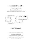
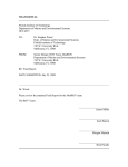
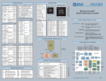
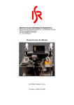
EEL 4914 Senior Design
Final Design Report
December 5th Fall 2007
Fresh Water Aquarium Monitor
Team Name: “Finding Nemo”
Submitted by:
Mike Arms
[email protected]
727.560.1663
Beth Spalding
[email protected]
352.870.7232
Table of Contents
I.
II.
III.
IV.
V.
VI.
VII.
VIII.
IX.
X.
XI.
XII.
XIII.
XIV.
INTRODUCTION
ABSTRACT
TECHNICAL OBJECTIVES
PROJECT FEATURES
CONCEPT/TECHNOLOGY
PRODUCT COMPARISON
PROJECT ARCHITECTURE
HARDWARE/SOFTWARE
DESIGN PROCEDURE
FLOWCHARTS/DIAGRAMS
BILL OF MATERIALS
USER MANUAL
GANTT CHART/RESPONSIBILITIES
APPENDICIES
1
1
2
2
3
5
6
8
13
14
15
16
19
21
I. INTRODUCTION
This project has very practical applications to almost every individual who has interest in
owning a fresh water aquarium or who already owns a fresh water fish aquarium. For
example, if a family leaves their home for a week long vacation, instead of trying to find
someone to care for the aquarium while they are away, the fish monitor will feed the fish,
monitor the temperature and PH levels, and adjust accordingly. This device will have
great value for those individuals who value the health of their fresh water friends.
Existing commercial products are very costly and provide many features that the average
aquarium owner may not use or need. Commercial available features include password
protection, water conductivity, weather simulation, sunrise and sunset simulation, and
ORP (oxidation reduction potential). All of these features are excess for the average
owner. Costs range anywhere from $150 upwards to $400, more than an owner would
want to pay if their aquarium only cost around $50. Our product will minimize cost and
provide only the basic features needed to successfully monitor and maintain a fresh water
aquarium.
II. ABSTRACT
This project was realized over the summer when a close friend received a fresh water
aquarium as a gift. One afternoon, the fish were found with small white spots all over
them. It turned out to be a bacterial infection and something that could have easily been
prevented if the water temperature was kept between a certain levels.
Project “Finding Nemo” aims to monitor and control the temperature, PH levels, and feed
the fish in a fresh water fish aquarium. The temperature will be monitored using a basic
temperature sensor and the temperature adjustment will be performed by turning on or off
a light. The PH levels will be monitored using a color sensor and the levels will be
adjusted according to the user’s discretion. The technical challenges this team will face
is programming the monitor for temperature and PH, and working with the color sensor.
Typical PH sensors are difficult to work with and on average, last only a year.
At the end of the term, this outcome we expect is to build a working aquarium monitor to
monitor the temperature and PH levels within the tank. The device will be able to store
user input as to when and how often the fish will be fed, at what temperature the water
should be kept, and the required PH levels. It will a provide feedback of the current
levels and adjust the temperature accordingly if the levels are out of the specified user
input.
III. TECHNICAL OBJECTIVES
This project will use basic DC wall power. There will be a temperature sensor to monitor
the water and another sensor to measure the pH. The pH levels can be adjusted at the
user’s discretion while the temperature will be corrected automatically. A step motor will
be used to dispense food. A microprocessor will take in the data from the sensors and
output the data to an LCD screen. The user will input the range of acceptable conditions
of the aquarium as well as the desired number of feedings per day on a keypad.
IV. PROJECT FEATURES
In order to minimize cost and facilitate ease of use, this product will have the necessary,
but minimal features.
Main Objective
Our goal is to market this product to the average aquarium owner, so a basic, userfriendly product is a must.
Features
LCD Display – this part of the device will be used to enter user-defined inputs for
temperature, pH and fish feeding time, through basic push buttons and display the
current temperature and pH levels.
Push-Button Input – minimal push-buttons will be used as the means for entering
the desired data.
Temperature monitoring and control – the device will monitor the temperature of
the aquarium and then display the temperature of the aquarium, and if the
temperature is out of the user-specified range, the device will turn on/off a lamp
to adjust the temperature.
PH monitoring – the device will monitor and display the current pH readings and
notify the user if the pH is out of the user-defined range.
Fish feeder – the device will contain a step motor with rotating cavity to provide
food to feed the fish. At the user-defined time, the motor will dispense the food to
the aquarium.
V. CONCEPT/TECHNOLOGY
PIC Microcontroller
We chose the PIC over other controllers based on the wide array of features
available which are appropriate for the needs of this project. It is widely available,
has a very low cost, wide range of available development tools, and the
availability of a real-time clock. It has a variety of features including a CPU,
RAM, ROM, I/O lines, and can store and run a program.
LCD Display
A basic LCD display will interface with the PIC Microcontroller in order to
display the information pertaining to the temperature and pH sensors.
Real-Time Clock
We chose to use a separate Real-Time Clock instead of the one on the PIC
Microcontroller because it is more stable than the PIC. It is more accurate and
will not fluctuate with a change in load.
Temperature Sensor
This sensor will take analog temperature data and then convert the value to a
digital format through the use of the microcontroller. There are many temperature
sensors available that easily interface with the PIC Microcontroller. We chose a
Fahrenheit temperature sensor because converting to Kelvin or Celsius with the
PIC loses some accuracy in the decimal place.
PH sensor
PH sensors test how basic or acidic the liquid is and can be translated into a
concentration of hydrogen ions. The measurement ranges between 0 and 14. A
very acidic solution has a low pH value from 0 to 2, corresponding to a large
concentration of hydrogen ions. A basic solution has a high pH value from 12 to
14, corresponding to a small number of hydrogen ions. It is important to note that
over time, the electrical properties in the pH measuring electrodes change, so the
electrode will eventually have to be replaced. This makes typical pH sensors
unfavorable to use.
We chose to use a color sensor instead of the more common pH sensors because
of its wide range of uses, consistent readings and the fact that it will not need to
be replaced, unlike basic pH sensors. The current method for testing the pH is
adding the appropriate chemicals to a small vial of the aquarium water and then
inserting it into the pH testing device, where the color sensor reads the intensity of
the water color in the vial and displays the results on the LCD. The color sensor
could also be adapted to test for ammonia and nitrate levels.
Stepper Motor
The stepper motor is ideal for feeding the fish. A stepper motor will run after a
pulse of electricity and this pulse will rotate the motor by a predefined increment
in a step fashion and has a high degree of precision. By using the step motor, we
will be able to control precisely how much food we want to feed the fish and
while using minimal power, unlike other types of motors.
VI. PRODUCT COMPARASION
After deciding on this design product, we researched to see if there were any comparable
existing products. We can see from the monitors introduced below that they are not only
expensive, but have many more features than the average aquarium owner would need.
Digital Aquatics ReefKeeper 2
(AquaDirect Link)
Features – fully enclosed stand-alone
device. PH monitor, interface with PC,
several channels, different modes,
timers, wavemaker, digital
thermometer and temperature control,
fan/chiller control, high power
Cost - $49.00
AquaController Jr, 3 and 3 Pro (Neptune Systems Link)
Features – fully enclosed, stand-alone device. This device includes pH, Temperature,
ORP, Cond and DO monitoring and control, Ethernet port, e-mail alarms, telnet server,
lighting control, wavemaker, seasonal variations, digital calibration (a picture of each
device is shown below).
Cost – $149.95 to $649.95
VII. PROJECT ARCHITECTURE
PCB Schematic
Project Architecture – A high level description of how the parts in your project work
together.
VIII. HARDWARE/SOFTWARE
PIC Microcontroller
We chose to use the PIC18F4620 because it is the largest one available with a
wide range of features required for our design.
- Operating voltage: 2.0V to 5.5V
- Internal real-time clock and oscillator
- 10-bit ADC, 13 channels at 100K samples per second
- Program Memory: 65536 bytes
- RAM size: 3968 bytes
- EEPROM data size: 1024 bytes
- I/O pins: 36
Figure – PIC18F4620 Pin-out
LCD Display
The LCD display provided in the senior design class was very basic and provided
two lines with twenty characters each, which is sufficient for our design.
Figure – 20x2 LCD Screen and Device Front Panel
Real-Time Clock
We used the PCF8583 to keep track of time and to store memory that needed a battery
back-up.
Temperature Sensor
Since we wanted to display the temperature in Fahrenheit, the LM34 temperature
sensor was the most feasible solution. It was very inexpensive and widely available. The
output voltage of the sensor is linearly proportional to the Fahrenheit temperature on a
10.0mV/°F scale, has a range of -50°F to 300°F range, has low self heating, and does not
require any outside calibration or programming conversions to obtain the correct value.
The figure below shows the configuration for a basic temperature sensor and its
corresponding current and temperature curve. For the basic configuration without using
any resistors, the temperature range stops at 0°F, which is sufficient because the
temperature of the fish tank is not expected to drop below 65°F.
Figure – LM34 Fahrenheit Temperature Sensor DIP and Curve
PH sensor
The TCS230 was used to read the color of the pH from a standard liquid test kit. The
color sensor outputs a PMW signal that is read by the microprocessor. As the intensity of
the red, green, or blue light increases the pulse widths get smaller. The time between two
pulses is measured of one particular color and then compared to that of the other colors.
The ratio is used to determine the shade of the color.
The vial containing the water to be tested and pH chemicals will be inserted into the
opening at the face of the device. A diagram of the color sensor compartment can be
seen in Figure X. The color sensor will then take samples of the color in the vial and
output the results to the LCD. If the pH is out of the desired range, the user can make the
decision to adjust the pH of the water.
Figure. PH Sensor Enclosure with Color Sensor and Test Vial.
Many samples were recorded of solutions varying in pH. The samples were grouped to
what they appear to represent on the color chart. The data was plotted and equations were
calculated. The red to green ratio was the best fit and most predictable. This equation was
implemented into the Microprocessor.
5.25
5
4.75
4.5
4.25
4
3.75
3.5
3.25
3
2.75 y = 1.2504x - 6.2334
2.5
R2 = 0.9912
2.25
2
1.75
1.5
1.25
1
0.75
0.5
0.25
0
5.8
6
6.2 6.4 6.6
y = 0.0002e1.349x
R2 = 0.9666
R/G vs pH
R/B vs pH
G/B vs pH
Linear (G/B vs pH)
Expon. (R/B vs pH)
Linear (R/G vs pH)
y = 0.6339x - 3.5348
R2 = 0.9241
6.8
pH
7
7.2
7.4
7.6
7.8
8
This technology can also be adapted to testing for Ammonia, Nitrate and Oxidation levels,
as the less advanced method of using test strips or litmus paper is the same method to test
for pH. These elements will obtain a certain color depending on the level of each in the
water, and the color sensor can be programmed to identify the range for those elements.
Stepper Motor
A stepper motor is an electromechanical device that rotates in discrete angular
steps. The angle of rotation is dependent on the sequence of pulses applied at the input.
It has very precise control and is ideal for this situation because the fish feeding
mechanism needs precise and limited rotation.
We are using the 20M020D1B bipolar, two-phase stepper motor which has 18º of
precision, meaning each step it rotates 18º. In conjunction we are also using a FAN8200
low voltage stepping motor driver. The device we built to contain the fish food and
dispense it to the fish tank has four compartments with dividers located 90 º apart. This
means we need 90º/18º = 5 steps in order to rotate enough to dispense the food.
The first figure is a drawing of the feeding mechanism. There is a food reservoir
that holds the food until the dispenser is rotated. After the stepper motor rotates the
dispenser, gravity brings food into the next empty compartment.
Figure – Feeding Mechanism
A certain sequence is required in order to power the stepper motor. A signal is
sent from the PIC through the driver and then the output to the driver moves the stepper
motor. The driver is basically two logic flip-flops or four inverters. The motor is
energized in full step mode, meaning two phases can be energized at a given time. A
diagram of the driver and the input and output sequences required to power the motor is
shown below.
Once the entire device is set up on the fish tank with food in the food reservoir,
the motor will need to rotate the dispenser once in order for the food to be on either the 0
or 180 mark; this way, once the set time is reached to feed the fish, the food will dispense
properly.
Figure – Stepper Motor Driver and Input and Output Sequence
IX. DESIGN PROCEDURE
Once we came up with an idea for a project, we brainstormed about features and
hardware we would need to implement the task. Since we knew what features we wanted
– temperature and pH sensing, automatic feeding and a basic user interface, we
researched available options for these features.
We decided on each hardware device based on the project needs. We chose the PIC
18F4620 after adding up the I/O pins we would need – we originally calculated around
20 I/O pins and ended up using all but two of the pins. We chose the LM34 temperature
sensor because of its ease of use and the fact that the output voltage is linear to the
Fahrenheit. We chose a stepper motor for the fish feeder because it has very precise
control. After doing extensive research on pH sensors, we found a new approach to
testing the pH – using a color sensor. Later in the semester we also realized that the color
sensor could also be adapted to test for Ammonia levels, Nitrate levels and other
chemicals typically adjusted in aquariums. We used a separate real-time clock due to its
stability.
Once we received all the parts, we split the responsibilities between the two of us and
programmed on two breadboards. That way, each individual was in charge of certain
aspects of the project, and if one of the breadboards or one of the components on the
board failed, we wouldn’t have to move the entire project to a new board or risk
damaging other components.
For the enclosure, we chose materials that were easy to work with. The plastic housing
was purchased for a local retailer and was easy to drill and cut holes for the components.
We used balsa wood for the rotating portion of the feeder, once again, because it was
easy to shape. A basic funnel was the container to hold the fish food.
X. Flowcharts & Diagrams
LCD
Light
Keypad
PIC Microcontroller
120 VAC Relay
Feeder
Motor
Temperature
Sensor
pH Sensor
X. BILL OF MATERIALS
PIC Microcontroller
Temperature Sensor
Color Sensor
RTC
Transistor
Diode
Cap (0.1 uf)
Cap (0.47 uf)
Cap electrolytic (33uF)
Resistor (10K)
Resistor (4.7k)
Resistor (1K)
Motor
Relay
Fuse
LCD
Motor Driver
Crystal Oscillator
Potentiometer
Total Cost
P/N
18F4620
LM34
TCS230-LM
8583
2N3189
1N4148
OUZ-SS-105D
FAN8200
S591
6P320K
Price per
Amount Each
Total
1
$10.20 $10.20
2
$2.51
$5.02
1
$59.95 $59.95
1
$2.48
$2.48
1
$0.75
$0.75
4
$0.10
$0.40
5
$0.25
$1.25
1
$0.20
$0.20
1
$0.12
$0.12
2
$0.30
$0.60
3
$0.30
$0.90
1
$0.80
$0.80
1
$19.60 $19.60
1
$1.15
$1.15
1
$2.87
$2.87
1
$10.00 $10.00
1
$0.80
$0.80
1
$1.16
$1.16
1
$3.00
$3.00
$121.25
This cost, $121.25, is in the range between the two lowest priced competing
products. The color sensor was the most expensive part in this design. If we had decided
to use the more common pH sensor, the cost would be cut significantly, but the pH leads
would have to be replaced often which would increase the price over time. The product
with the color sensor might be more expensive, but it requires little to no maintenance
and can be kept in full working condition for years.
XII. USER MANUAL
XIII. Gantt Chart
Task Name
Project Research
Preliminary Design Report
Order Parts
Circuit Design
Breadboard (Preliminary Assembly)
Programming
Preliminary Debug
MIL PCB
Debug/Testing
Packaging
Fine Tune Project
Report
Final Presentation
0
1
2
4
4
5
6
7
7
9
9
11
12
Mike
0
0
2
0
0
0
0
1
0
1
0
0
0
Beth
0
2
0
0
0
0
0
0
3
0
0
2
0
Both
1.5
0
0
3
2.5
4
2
0
0
0
2
0
1
1.5
3
4
7
6.5
9
8
8
10
10
11
13
13
RESPONSIBILITIES
At the beginning, we had alternately divided up the responsibilities. As the
semester went on, we divided up the responsibilities based on strengths and weaknesses.
Since Mike had the most programming knowledge and experience, he was responsible
for programming the color sensor, real-time clock and user interface for the device. He
was also responsible for the physical assembly of the feeder and installing the LCD and
buttons for the enclosure. Because Beth has a less diverse programming background, she
was responsible for programming the temperature sensors and the motor for the fish
feeder. She was also responsible for soldering the components to the PCB board and the
majority of the writing.
Mike
1.
Programming
- Color Sensor
- Real-Time Clock
- User Interface
2. Protel
3. Mechanical
Beth
1. Programming
- Temperature Sensor
- Stepper Motor
2. Soldering board
XIV. APPENDICIES
'****************************************************************
'* Name : FishMonitor
*
'* Author : Mike Arms, Beth Spalding
*
'* Notice : Copyright (c) 2007
*
'*
: All Rights Reserved
*
'* Date : 10/9/2007
*
'* Version : 1.0
*
'* Notes :
*
'*
:
*
'****************************************************************
DEFINE LCD_DREG PORTA 'LCD data port
DEFINE LCD_DBIT 0 'LCD data starting bit 0 or 4
DEFINE LCD_RSREG PORTA 'LCD register select port
DEFINE LCD_RSBIT 4 'LCD register select bit
DEFINE LCD_EREG PORTB 'LCD enable port
DEFINE LCD_EBIT 3 'LCD enable bit
DEFINE LCD_BITS 4 'LCD bus size 4 or 8
DEFINE LCD_LINES 2 'Number lines on LCD
DEFINE LCD_COMMANDUS 2000 'Command delay time in us
DEFINE LCD_DATAUS 50 'Data delay time in us
DEFINE HSER_RCSTA 90h
DEFINE HSER_TXSTA 20h
DEFINE HSER_BAUD 9600
DEFINE HSER_SPBRG 6
DEFINE HSER_CLROERR 1
'*****ALIASES******************************************************
CS_S0 VAR PORTC.0
CS_S1 VAR PORTC.1
CS_INPUT VAR PORTC.2
CS_S2 VAR PORTA.6
CS_S3 VAR PORTA.7
CS_OE VAR PORTC.5
CS_LED VAR PORTC.6
ALERT VAR PORTB.0
LIGHT_EN VAR PORTC.7
SDA VAR PORTC.4
SCL VAR PORTC.3
i2c_read CON 1
i2c_write CON 0
i2c_out VAR BYTE
i2c_in VAR BYTE[6]
i2c_ack VAR BIT
temp VAR WORD
UP VAR PORTB.7
DOWN VAR PORTB.6
LEFT VAR PORTB.5
RIGHT VAR PORTB.4
SEL VAR PORTB.1
Position VAR BYTE
Hours VAR BYTE
Minutes VAR BYTE
'****REGISTER CONFIGURATION**************************************
OSCCON = %01100010
CCP1CON = %00000101 'Capture on rising edge
T3CON = %10000001
T1CON = %10001001
'*********************A/D Setup*****************************************
DEFINE ADC_BITS 10
' Set A/D for 10-bit operation
DEFINE ADC_CLOCK 3
' Set A/D clock
DEFINE ADC_SAMPLEUS 50 ' Set A/D sampling time @ 50 uS
' bit# 76543210
ADCON1 = %00001000
' ADCON1 - A/D control reg 1
' bit3-0 = 0010, A/D port config, AN0-AN6 analog,
' bit4 = 0, VREF+ = VDD
' bit5 = 0, VREF- = VSS
ADCON2 = %10111110
' bit7: right Justified
'*****PORT DIRECTION ASSIGNMENTS**********************************
TRISE.0 = 1
' set RE1/AN5 to input for water temp reading
TRISA = %00100000
' set all of port A output for LCD
' set RA5/AN4 to input for room temp reading
TRISB.0 = 0 ' B.0 is output
TRISC.2 = 1 'Input for CCP1
TRISC.7 = 0
TRISC.0 = 0
TRISC.1 = 0
TRISC.3 = 0
TRISC.4 = 0
TRISC.5 = 0
TRISC.6 = 0
TRISC.3 = 0 'SCL output
TRISB.1 = 1
TRISB.7 = 1
TRISB.6 = 1
TRISB.5 = 1
TRISB.4 = 1
'*****VARIABLES**************************************************
'********************Room temp A/D Variable Definitions********************
rsamples VAR WORD
' Multiple A/D sample accumulator
rsample VAR BYTE
' Holds number of samples to take
rtemp VAR BYTE
' room temp storage
rbinary1 VAR BYTE
' storage for binary value
rtemp1 VAR BYTE
DEG CON 223
' write a degree mark on the LCD
rsamples = 0
'********************Water temp A/D Variable Definitions*******************
wsamples VAR WORD
' Multiple A/D sample accumulator
wsample VAR BYTE
' Holds number of samples to take
wtemp VAR BYTE
' water temp storage
wbinary1 VAR BYTE
' storage for binary value
wtemp1 VAR BYTE
wsamples = 0
H20Temp VAR BYTE 'Variable that holds the set temp
TempAdd VAR BYTE
TempAdd=$20
'Address on RTC where set temp in backed up
'********************Motor Variable Definitions***************************
steps VAR WORD
' storage for the # of steps
stepArray VAR BYTE(4) ' sets the number of available arrays
run VAR WORD
' storage for variable run
steps = 0
' initializes the step # to zero
run = 0
' initializes the run # to zero
'clear
' clears all registers
TRISD = %11110000
' sets D.0,1,2 to low (output) and the rest high
'CE1 var PORTD.0
'IN1 VAR PORTD.1
'IN2 VAR PORTD.2
'CE2 VAR PORTD.3
stepArray[0] = %00001001
stepArray[1] = %00001011
stepArray[2] = %00001111
stepArray[3] = %00001101
'****CS VARIABLES***********************************************
OldCap VAR WORD
NewCap VAR WORD
PulseW VAR WORD
Red VAR WORD
Green VAR WORD
Blue VAR WORD
T3OF VAR BYTE
SampDone VAR BYTE
EN_CS VAR BIT
pH VAR WORD[2]
DONE VAR BIT
RG VAR WORD
'****RTC VARIABLES*************************************************
Address VAR BYTE
SAddR VAR BYTE
SAddW VAR BYTE
Sec1 VAR BYTE
Sec10 VAR BYTE
Min1 VAR BYTE
Min10 VAR BYTE
Hour1 VAR BYTE
Hour10 VAR BYTE
WHour VAR BYTE
WMin VAR BYTE
IAMPM VAR BIT
AMPM VAR BYTE
AlarmNum VAR BYTE
AlarmAdd VAR BYTE
i VAR BYTE
AMin1 VAR BYTE 'LCD View of Alarm Contents
AMin10 VAR BYTE
AHour1 VAR BYTE
Ahour10 VAR BYTE
AAMPM VAR BYTE
AHour VAR BYTE[4] 'Raw Alarm Data
AMin VAR BYTE[4]
rHours VAR BYTE
rMinutes VAR BYTE
EN_Alarm VAR BIT
Buttons VAR BYTE
Busy VAR BIT
'*****INTERRUPT INITIALIZATION**********************************
ON INTERRUPT GoTo IntHandler
INTCON = %11000000 ' Enable global and pir interrupts
INTCON.3 = 1
'PORTB INTERRUPT
INTCON.0 = 0
'CLEAR PORTBIF
IPR1 = %00000100 ' Set CCP to high priority
'PIE2 = %00000010 ' Enable TMR3I
'PIE1 = %00000100 ' Enable CCP1 interrupt
PIR2.1 = 0
' Clear TMR3IF
PIR1 = %00000000 ' clear flags
'*****MAIN******************************************************
Buttons=PORTB
PORTB.0 = 1
T3OF = 0
SAddR = %10100001 'Slave Read
SAddW = %10100000 'Slave Write
EN_CS = 0 'CS Off
AlarmNum = 0 'No Alarms on Fresh Start
AlarmAdd = $10 'Address of First Alarm
EN_Alarm = 0 'Turn of Alarm Condition
Light_EN=0
DONE=0
Busy=0
Pause 2000
GoSub Init_Clock
GoSub CS_INT
'^^^^^^^^^^^^^^^^^^^^^^^^^^^^^^^^^^^^^^^^^^^^^^^^^^^^^^^^^^^^^^^
Main:
GoSub I2C_READ_TIME
GoSub WaterTemp
GoSub RoomTemp
Pause 500 ' Wait 500mS for LCD to startup
LCDOut $fe, 1 ' Clear LCD screen
Pause 1 ' Wait 1 millisecond
LCDOut $fe,$80 ' Move cursor to the beginning of the first line
LCDOut DEC1 Hour10,DEC1 Hour1,":",DEC1 Min10,DEC1 Min1,":",DEC1 Sec10,
DEC1 sec1, " "
IF AMPM == 0 Then
LCDOut "AM"
Else
LCDOut "PM"
EndIF
LCDOut "
",DEC2 rtemp1,DEG, "F"
LCDOut $FE,$C0
LCDOut "Water Temp=", DEC2 wtemp1,DEG, "F"
GoTo Main
'*****INITIALIZE COLOR SENSOR FOR READING***********************
CS_INT:
PIR2.1 = 0
' Clear TMR3IF
PIR1 = %00000000 ' clear flags
sampdone = 0
CS_S0 = 0 ' Set division for 1:50
CS_S1 = 1
CS_S2 = 0 's2s3'---red='00', blue='01', clear='10', green='11'
CS_S3 = 0
CS_LED = 0
CS_OE = 1
Return
'**********************Room Temp Reading Loop*************************
RoomTemp:
ADCON0 = %00010001
Pause 10
For rsample = 1 TO 20 ' Take 20 samples
ADCIN 4, rtemp
' Read analog chan AN4 into rtemp var
rsamples = rsamples + rtemp ' Accumulate 20 samples
Pause 10
' Wait 10ms per loop
Next rsample
rtemp = rsamples/20
' divide by # of samples
rbinary1 = rtemp
' store the number into the binary storage
rtemp1 = (rtemp*/500)>>2
rsamples = 0
' Clear old sample accumulator
Pause 75
Return
'**********************water Temp Reading Loop***************************
WaterTemp:
ADCON0 = %00010101
Pause 10
For wsample = 1 TO 20 ' Take 20 samples
ADCIN 5, wtemp
' Read analog chan AN5 into wtemp var
wsamples = wsamples + wtemp ' Accumulate 20 samples
Pause 10
' Wait 10ms per loop
Next wsample
wtemp = wsamples/20 ' divide by # of samples
wbinary1 = wtemp
' store the number into the binary storage
wtemp1 = (wtemp*/500)>>2
wsamples = 0
' Clear old sample accumulator
Pause 75
Return
'*****Get Color Sample*******************************************
GetSample:
PIR2.1 = 0
' Clear TMR3IF
PIR1 = %00000000 ' clear flags
pie2.1 = 1 'Turn on TMR3I
PIE1.2 = 1 'Turn on CCPI
Done = 0
LCDOut $fe,1
Pause 1
LCDOut $fe, $80
LCDOut "pH = "
While Done==0
Wend
GoSub DisplayColors
Buttons=PORTB 'Reading PortB will update the resting state, avoiding false
inturrupts
INTCON.0 = 0
Return
'***Display Colors**************************************************
DisplayColors:
'LCDOut $fe, 1 ' Clear LCD screen
'Pause 1 ' Wait 1 millisecond
'LCDOut $fe,$80 ' Move cursor to the beginning of the first line
'LCDOut "Red=", dec5 Red," ","Blue=", Dec5 Blue
'LCDOut $fe,$c0 ' Move cursor to the beginning of the second line
'LCDOut "Green=", dec5 Green, " "
RG=Green/10
IF (Red//RG)>(RG/2) Then
RG=8*((Red/RG)+1)
Else
RG=8*(Red/RG)
EndIF
pH[0]=(RG/10)+50
pH[1]=pH[0]//10
pH[0]=pH[0]/10
LCDOut DEC1 pH[0],".", DEC1 pH[1]
Pause 2000
Return
'**********************Fish Feeding Loop*********************************
FishFeed:
PORTD.0 = 1
PORTD.3 = 1
' sets portd.0 high for chip enable1
' sets portd.3 high for chip enable2
For run = 1 TO 5
' step through the sequence 5 times
GoSub motorRun ' go to the subroutine motorRun
Pause 150
Next run
' increment the run count
Pause 100
PORTD.0 = 0
PORTD.3 = 0
' sets portd.0 low for chip enable1 to disable
' sets portd.3 low for chip enable2 to disable
Return
'**********************Motor Rotation Loop*******************************
' Input 1234 Output 1234
' CE1 1111 Out1 1001
' IN1 0110 Out2 0110
' IN2 0011 Out3 1100
' CE1 1111 Out4 0011
motorRun:
Pause 100
steps = steps + 1
PORTD = stepArray[steps //4]
Pause 100
Return
Enable
'#######I2C COMMUNICATION#########################################
I2C_READ_TIME:
GoSub I2C_START 'Read Time
i2c_out=SAddW
GoSub I2C_TX
i2c_out=$02 'Start reading at Seconds address
GoSub I2C_TX
GoSub I2C_START
i2c_out=SAddR
GoSub I2C_TX
ShiftIn SDA, SCL, 0, [i2c_in[0]] 'Shift in first byte MSBF
ShiftOut SDA, SCL, 1, [%0\1] 'Send ACK = 0
ShiftIn SDA, SCL, 0, [i2c_in[1]] 'Shift in second byte MSBF
ShiftOut SDA, SCL, 1, [%0\1] 'Send ACK = 0
ShiftIn SDA, SCL, 0, [i2c_in[2]] 'Shift in first byte MSBF
ShiftOut SDA, SCL, 1, [%1\1] 'Send not acknowledge (NACK)=1
GoSub I2C_STOP
rMinutes = i2c_in[1] 'raw time data
rHours = i2c_in[2]
sec1 = i2c_in[0] & %00001111 'LCD viewable Time Format
Sec10 = i2c_in[0] >> 4
Min1 = i2c_in[1] & %00001111
Min10 = i2c_in[1] >> 4
Hour1 = i2c_in[2] & %00001111
Hour10= (i2c_in[2] >> 4) & %00000011
AMPM = (i2c_in[2] >> 6) & %00000001
IF AlarmNum !=0 AND AlarmNum <5 Then
GoSub I2C_START
'Read Alarms
i2c_out=SAddW
GoSub I2C_TX
i2c_out=$10 'AlarmAdd
GoSub I2C_TX
GoSub I2C_START
i2c_out=SAddR
GoSub I2C_TX
For i=0 TO (AlarmNum-1)
'i= 0,1,2,3
ShiftIn SDA, SCL, 0, [Amin[i]]
'Shift in AMinutes from ADDR=$00,02,O4,6
ShiftOut SDA, SCL, 1, [%0\1]
'Ack=0
ShiftIn SDA, SCL, 0, [Ahour[i]]
'Shift in MHour from ADDR=$01,03,05,07
IF i != (AlarmNum-1) Then
'Send ACK if more to read
ShiftOut SDA, SCL, 1, [%0\1] 'Send ACK = 0 if more data to get
EndIF
Next i
ShiftOut SDA, SCL, 1, [%1\1] 'Send not acknowledge (NACK)=1
GoSub I2C_STOP
For i=0 TO (AlarmNum-1)
IF rHours == Ahour[i] AND rMinutes == AMin[i] AND sec1 == 0 AND sec10 == 0
Then
GoSub FishFeed
EndIF
Next i
EndIF
IF H20Temp > WTemp1 Then
Light_EN=1
Else
Light_EN=0
EndIF
Return
I2C_START:
High SDA
High SCL
Low SDA
Low SCL
Return
I2C_STOP:
Low SDA
High SCL
High SDA
Pause 1
Return
I2C_RX:
ShiftIn SDA, SCL, 0, [i2c_in[0]] 'Shift in first byte MSBF
ShiftOut SDA, SCL, 1, [%0\1] 'Send ACK = 0
ShiftIn SDA, SCL, 0, [i2c_in[1]] 'Shift in second byte MSBF
ShiftOut SDA, SCL, 1, [%1\1] 'Send not acknowledge (NACK)=1
Return
I2C_TX:
ShiftOut SDA,SCL,1,[i2c_out] 'Shift out "i2c_out" MSBF
ShiftIn SDA,SCL,0,[i2c_ack\1] 'Receive ACK bit
IF i2c_ack != 0 Then
GoSub error
EndIF
Return
I2C_WRITE_TIME:
GoSub I2C_START
i2c_out = SAddW
GoSub I2C_TX
i2c_out = Address 'Start at Minutes address
GoSub I2C_TX 'Send Address
i2c_out = WMin
GoSub I2C_TX
i2c_out = WHour
GoSub I2C_TX
GoSub I2C_STOP
Return
Init_Clock:
GoSub I2C_START
i2c_out = SAddW
GoSub I2C_TX
i2c_out = $00
GoSub I2C_TX
i2c_out = %00000000 'RTC Control Setup
GoSub I2C_TX
GoSub I2C_STOP
GoSub I2C_START
i2c_out = SAddW
GoSub I2C_TX
i2c_out = $08
GoSub I2C_TX
i2c_out = %00000000 'Alarm Control Setup
GoSub I2C_TX
GoSub I2C_STOP
GoSub I2C_START 'Read Temp Backup
i2c_out=SAddW
GoSub I2C_TX
i2c_out=TempAdd 'Start reading TempAdd
GoSub I2C_TX
GoSub I2C_START
i2c_out=SAddR
GoSub I2C_TX
ShiftIn SDA, SCL, 0, [i2c_in[0]] 'Shift in first byte MSBF
ShiftOut SDA, SCL, 1, [%1\1] 'Send not acknowledge (NACK)=1
GoSub I2C_STOP
H20Temp=i2c_in[0]
GoSub I2C_READ_TIME 'Get Time and Alarms
IF hour10 == 0 AND AMPM == 0 Then 'Set up RTC on fresh start
GoSub I2C_START
i2c_out = SAddW
GoSub I2C_TX
i2c_out = $04
GoSub I2C_TX
i2c_out = %10010010 'Set default time to 12:00AM
GoSub I2C_TX
GoSub I2C_STOP
GoSub I2C_START
i2c_out = SAddW
GoSub I2C_TX
i2c_out = $0F
'Start at AlarmNum and clear everything
GoSub I2C_TX
i2c_out = $00
GoSub I2C_TX 'AlarmNum
GoSub I2C_TX 'A1
GoSub I2C_TX
GoSub I2C_TX 'A2
GoSub I2C_TX
GoSub I2C_TX 'A3
GoSub I2C_TX
GoSub I2C_TX 'A4
GoSub I2C_TX
GoSub I2C_STOP
GoSub I2C_START
i2c_out = SAddW
GoSub I2C_TX
i2c_out = TempAdd 'Start at temperature address
GoSub I2C_TX 'Send Address
i2c_out = 70
GoSub I2C_TX
GoSub I2C_STOP
EndIF
AHour[0]=0
AHour[1]=0
AHour[2]=0
AHour[3]=0
AMin[0]=0
AMin[1]=0
AMin[2]=0
AMin[3]=0
'Alway clear unknown memory contents on PIC boot
GoSub I2C_START
'Read AlarmsNum backup
i2c_out=SAddW
GoSub I2C_TX
i2c_out=$0F
'Point to AlarmNum backup Address
GoSub I2C_TX
GoSub I2C_START
'Repeat Start to read
i2c_out=SAddR
GoSub I2C_TX
ShiftIn SDA, SCL, 0, [AlarmNum] 'Shift in first byte MSBF
ShiftOut SDA, SCL, 1, [%1\1] 'Send not acknowledge (NACK)=1
GoSub I2C_STOP
Return
Set_Temp:
Disable
Pause 200 ' Wait 10mS for LCD to startup
LCDOut $fe, 1 ' Clear LCD screen
Pause 1 ' Wait 1 millisecond
LCDOut $fe,$80 ' Move cursor to the beginning of the first line
LCDOut "Water Temp <= ", DEC2 H20Temp, DEG, "F"
repeat
IF up == 1 Then
Pause 50
IF H20Temp <90 Then
H20Temp=H20Temp+1
EndIF
GoTo set_temp
EndIF
IF down == 1 Then
Pause 50
IF H20Temp >65 Then
H20Temp=H20Temp-1
EndIF
GoTo set_temp
EndIF
until Sel==1
GoSub I2C_START
i2c_out = SAddW
GoSub I2C_TX
i2c_out = TempAdd 'Start at temperature address
GoSub I2C_TX 'Send Address
i2c_out = H20Temp
GoSub I2C_TX
GoSub I2C_STOP
Pause 50
Buttons=PORTB
'Reading PortB will update the resting state, avoiding false
inturrupts
INTCON.0 = 0
Enable
Return
TimeInput:
Disable
Position = 0
LCDOut $FE, $0F 'Blinking cursor on
Update: Pause 200 ' Wait 10mS for LCD to startup
LCDOut $fe, 1 ' Clear LCD screen
Pause 1 ' Wait 1 millisecond
LCDOut $fe,$80 ' Move cursor to the beginning of the first line
LCDOut DEC2 Hours,":",DEC2 Minutes," "
IF IAMPM == 0 Then
LCDOut "AM"
Else
LCDOut "PM"
EndIF
IF Position == 0 Then
LCDOut $FE, 2 'Return home (beginning of first line)
LCDOut $FE, $14
EndIF
IF Position == 1 Then
LCDOut $FE, 2
For i=1 TO 4
LCDOut $FE, $14
Next i
EndIF
IF Position == 2 Then
LCDOut $FE, 2
For i=1 TO 6
LCDOut $FE, $14
Next i
EndIF
Repeat
IF up == 1 Then
Pause 50
IF Position == 0 AND Hours < 12 Then
Hours = Hours + 1
Else
IF Position == 0 AND Hours == 12 Then
Hours = 1
EndIF
EndIF
IF Position == 1 AND Minutes < 59 Then
Minutes = Minutes + 1
Else
IF Position == 1 AND Minutes == 59 Then
Minutes = 0
EndIF
EndIF
IF Position == 2 AND IAMPM == 0 Then
IAMPM = 1
EndIF
GoTo Update
EndIF
IF down == 1 Then
Pause 50
IF Position == 0 AND Hours > 1 Then
Hours = Hours - 1
Else
IF Position == 0 AND Hours == 1 Then
Hours = 12
EndIF
EndIF
IF Position == 1 AND Minutes > 0 Then
Minutes = Minutes - 1
Else
IF Position == 1 AND Minutes == 0 Then
Minutes = 59
EndIF
EndIF
IF Position == 2 AND IAMPM == 1 Then
IAMPM = 0
EndIF
GoTo Update
EndIF
IF Left == 1 Then
Pause 50
IF Position == 1 Then
Position = 0
Else
IF Position == 2 Then
Position=1
Else
IF Position == 0 Then
Position = 2
EndIF
EndIF
EndIF
GoTo update
EndIF
IF Right == 1 Then
Pause 50
IF Position == 1 Then
Position = 2
Else
IF Position == 2 Then
Position=0
Else
IF Position == 0 Then
Position = 1
EndIF
EndIF
EndIF
GoTo update
EndIF
until sel==1
LCDOut $FE, $0C
WHour = ((Hours/10) << 4) | (Hours//10) | (IAMPM << 6) | %10000000
WMin = ((Minutes/10) << 4)| (Minutes//10)
GoSub I2C_WRITE_TIME
Pause 50
Buttons=PORTB
'Reading PortB will update the resting state, avoiding false
inturrupts
INTCON.0 = 0
Enable
Return
SetAlarms:
Disable
Pause 50
LCDOut $fe, 1 ' Clear LCD screen
Pause 1 ' Wait 1 millisecond
LCDOut $fe,$80 ' Move cursor to the beginning of the first line
LCDOut "How Many Feedings?"
Repeat 'Wait for Select
Pause 200
LCDOut $fe, $c0
LCDOut DEC1 AlarmNum
IF up == 1 AND AlarmNum < 4 Then
Pause 50
AlarmNum = AlarmNum+1
EndIF
IF down == 1 AND AlarmNum >0 Then
Pause 50
AlarmNum = AlarmNum-1
EndIF
until Sel==1
IF AlarmNum == 0 Then
Buttons=PORTB 'Reading PortB will update the resting state, avoiding false
inturrupts
INTCON.0 = 0
Return
EndIF
For i=0 TO (AlarmNum-1)
'i=0,1 2 3
Address = $10 + 2*i
'$10,$12,$14,$06
LCDOut $fe,1
Pause 1
LCDOut $fe,$80
LCDOut "Feeding ", DEC1 (i+1)
Pause 1000
'Convert BCD
IF Amin[i] != 0 AND AHour[i] != 0 Then 'Makes previously set alarms
viewable
AMin1 = AMin[i] & %00001111
AMin10 = AMin[i] >> 4
AHour1 = AHour[i] & %00001111
Ahour10= (AHour[i] >> 4) & %00000011
AAMPM = (AHour[i] >> 6) & %00000001
Minutes = AMin1+10*AMin10
Hours = AHour1 + 10*AHour10
IAMPM = AAMPM
Else
Minutes = 0 'Default Alarm Values
Hours = 12
IAMPM = 0
EndIF
GoSub TimeInput
Next i
GoSub I2C_START 'Backup the Number of Alarms
i2c_out = SAddW
GoSub I2C_TX
i2c_out = $0F 'AlarmNum Backup Address
GoSub I2C_TX 'Send Address
i2c_out = AlarmNum
GoSub I2C_TX
GoSub I2C_STOP
Pause 50
Buttons=PORTB
'Reading PortB will update the resting state, avoiding false
inturrupts
INTCON.0 = 0
Enable
Return
error:
Pause 500 ' Wait 500mS for LCD to startup
LCDOut $fe, 1 ' Clear LCD screen
Pause 1 ' Wait 1 millisecond
LCDOut $fe,$80 ' Move cursor to the beginning of the first line
LCDOut "no ack received" ' Display
Pause 500
GoTo error
Return
'*****INTERRUPT HANDLERS****************************************
Disable
IntHandler:
'~~~~~CCP1~~~~~~~~~~~~~~~~~~~~~~~~~~~~~~~~~~~~~~~~~~~~~~~~~~~~~~~
IF pir1.2 == 1 AND PIE1.2 == 1 Then ' The CCP1 ISR
PIR1.2 = 0 'Clear CCP1IF
OldCap = NewCap
NewCap = (CCPR1H << 8) | CCPR1L
PulseW = Newcap - oldcap
GoTo exitint2
EndIF
'~~~~~Timer 3~~~~~~~~~~~~~~~~~~~~~~~~~~~~~~~~~~~~~~~~~~~~~~~~~~~~
IF PIR2.1 == 1 AND PIE2.1 == 1 Then 'The TMR3OF ISR
pir2.1 = 0
'Clear TMR3IF
IF T3OF == 0 Then
CS_S2 = 0 's2s3'---red='00', blue='01', clear='10', green='11'
CS_S3 = 0
CS_OE = 0
IF SampDone == 0 Then
Red=0
Blue=0
Green=0
EndIF
EndIF
IF t3of == 1 Then
CS_S2 = 0 's2s3'---red='00', blue='01', clear='10', green='11'
CS_S3 = 1
CS_OE = 0
EndIF
IF t3of == 2 Then
CS_S2 = 1 's2s3'---red='00', blue='01', clear='10', green='11'
CS_S3 = 1
CS_OE = 0
EndIF
IF T3OF == 1 Then
red = PulseW+Red
EndIF
IF t3of == 2 Then
Blue = PulseW+Blue
EndIF
IF t3of == 3 Then
Green = Pulsew+Green
EndIF
IF t3of == 3 Then
IF sampdone = 1 Then
PIE1.2 = 0 'Turn off CCP1
PIE2.1 = 0 'turn of TMR3I
SampDone=0
T3OF=0
Red=Red
Green=Green
Blue=Blue
CS_OE=1
DONE=1
Else
t3of = 0
sampdone = sampdone + 1
EndIF
Else
t3of = t3of + 1
EndIF
GoTo exitint2
EndIF
'+++++TIME/ALARM/Color Sensor+++++++++++++++++++++++++++++++++++
IF INTCON.0 == 1 AND Busy==0 Then
Buttons=PORTB
Buttons=Buttons>>4
INTCON.0 = 0
IF Buttons==%00000001 Then 'right
Pause 200
GoSub fishfeed
GoTo exitint
EndIF
IF Buttons==%00000010 Then 'left
Pause 200
GoSub GetSample
GoTo exitint
EndIF
IF Buttons==%00001000 Then
Pause 200
Busy=1
GoSub options
Busy=0
GoTo exitint
EndIF
'up
IF Buttons==%00000100 Then
Pause 200
Busy=1
GoSub set_temp
Busy=0
GoTo exitint
EndIF
'down
GoTo exitint 'no match
options:
Pause 10 ' Wait 10mS for LCD to startup
LCDOut $fe, 1 ' Clear LCD screend
Pause 1 ' Wait 1 millisecond
LCDOut $fe,$80 ' Move cursor to the beginning of the first line
LCDOut "<=Clock | Feedings=>" ' Display
LCDOut $fe,$c0 ' Move cursor to the beginning of the second line
LCDOut "Select to Exit"
Pause 250
repeat
IF right == 1 Then 'Set Feeding Alarm
Pause 50
GoSub SetAlarms
GoTo endoptions
EndIF
IF left == 1 Then 'Set Clock
Pause 50
Address = $03
Minutes = Min1+10*Min10
Hours = Hour1 + 10*Hour10
IAMPM = AMPM
GoSub TimeInput
GoTo endoptions
EndIF
until sel == 1
endoptions:
Return
EndIF
exitint:
Pause 500
Buttons=PORTB
INTCON.0 = 0
exitint2:
'________________________________________________________________
Resume
Enable