1
SZA-NA(FM) Operation Manual
Thank you for purchasing the HOCHIKI Very High Sensitivity Smoke Detection System SZA-NA(FM).
This manual describes safety precautions and instructions to use the SZA-NA(FM) correctly. Read this
manual carefully before using the SZA-NA(FM). Keep this manual near for quick reference. HOCHIKI
shall not be liable for loss of profits or benefits, indirect, special, consequential or other similar damages
arising out of improper use of this product, for any reason. The content of this manual is subject to change
without any prior notice.
1700-10330 HA-06-141
Issued:
August 4, 2006
Table of Contents
1.
PARTS DESCRIPTION AND FUNCTIONS ...................................................................................... 1
1-1 Front Panel ................................................................................................................................... 1
1.2 Inside the SZA-NA(FM) .............................................................................................................. 2
2.
BASIC WIRING ................................................................................................................................... 4
3.
INITIAL SYSTEM STATUS AND NORMAL SMOKE DETECTION STATUS ............................. 5
4.
INDICATIONS AND OPERATION WHEN SMOKE IS DETECTED.............................................. 5
4.1 Indication When a Smoke Alarm Occurs ..................................................................................... 5
4.2 Resetting the Alarm...................................................................................................................... 5
5.
INDICATIONS AND OPERATION WHEN AN AIR FLOW FAULT IS DETECTED .................... 5
5.1 Indications When an Air Flow Fault Occurs (High Air Flow Fault or Low Air Flow Fault) ...... 6
5.2 Resetting the Air Flow Fault ........................................................................................................ 6
6.
INDICATIONS AND OPERATION WHEN FAULTS ARE DETECTED ........................................ 6
6.1 Monitoring Items .......................................................................................................................... 6
6.2 Indications When a Fault Occurs ................................................................................................. 6
6.3 Resetting the Faults ...................................................................................................................... 7
7.
LASER UNIT OPERATION TESTS ................................................................................................... 7
7.1 Automatic Laser Unit Test ........................................................................................................... 7
7.2 Manual Laser Unit Test ................................................................................................................ 7
8.
SETTINGS............................................................................................................................................ 7
8.1 Setting Procedure.......................................................................................................................... 8
8.2 Data Setting .................................................................................................................................. 8
9.
CONTACT OUTPUT STATUS ......................................................................................................... 14
9.1 Contact Output Status In Normal Monitoring ............................................................................ 14
9.2 Contact Output Status When Power to the SZA-NA(FM) is Lost ............................................. 14
10. SPECIFICATION ............................................................................................................................... 15
11. IF YOU HAVE ANY QUESTIONS, CONTACT .............................................................................. 15
1700-10330 HA-06-141
Issued:
August 4, 2006
I. SAFETY PRECAUTION
SYMBOLS AND MARKS
This manual contains various symbols and marking to alert and inform the user to prevent personal injury
and property damage. Read the notices and instructions below carefully before using the SZA-NA(FM).
WARNING
This safety reminder is given to items that are potentially dangerous to life and the
system. If these items are performed improperly, you may be seriously injured and in
extreme cases, loss of life may result. Operation of the system may be lost.
CAUTION
This safety reminder is given to items that are potentially dangerous to you and the
system. If these items are performed improperly, you may be injured and the system
may malfunction.
Prohibited items
Required items
Notices on installation and use of the product
This product is a Class 3B laser product.
Be sure to shut off power to the product before installing or cleaning the
product.
WARNING
Do not look into the sampling pipe from its opening. Exposure to a laser
beam can cause damage to your eyes.
Do not touch the inside of the product with a wet hand. You may get a severe
electrical shock and the product may be damaged.
CAUTION
Touch the head of a metallic screw to dissipate your static electricity before
opening the panel (to protect the internal circuitry of the product from damage
by static electricity).
Never disassemble or modify the product. Improper servicing may cause a
failure or malfunction of the product.
Avoid installing the product in the following places to prevent damage to the
product:
① Areas in which blockage of the exhaust port or inlet ports of the sampling
tube may occur.
② Areas of direct sunlight or exposure to high temperatures.
③ Areas in which high humidity, wet conditions, or significant dust buildup
can occur.
④ Areas near a high voltage source or places being affected by
electromagnetic induction.
⑤ Areas in which chemicals or gases are present.
Do not place objects or cabling on the product or smoke sampling pipe.
This is a precision instrument. Do not hit or drop the product.
Firmly couple the sampling pipe with the pipe joint. Any gap, clearance, or
hole on the joint will reduce the suction force.
Do not put your finger into the sampling pipe joint. The mesh guard in
the sampling pipe joint has a sharp edge.
1700-10330 HA-06-141
Issued:
August 4, 2006
1. PARTS DESCRIPTION AND FUNCTIONS
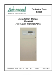
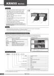
1-1 Front Panel
Spanner Screw
Alarm Level Indicators
Air Flow Fault Indicator
System Fault Indicator
POWER Indicator
RESET Switch
Spanner Screw
(1) Alarm Level Indicators
There are three alarm level indicators to indicate smoke density levels: Alarm 1, Alarm 2, and
Alarm 3. When detecting smoke, the SZA-NA(FM) turns on or blinks the appropriate
indicators Alarm 1, Alarm 2, or Alarm 3 according to the optical density of the smoke
detected.
.
When the smoke density level is at Alarm level 2 or Alarm level 3, the alarm indicator lights
together with the lower level alarm indicators.
Example: When the smoke density level is Alarm 3, the Alarm 3 indicator blinks and
the Alarm 2 and Alarm 1 indicators turn on.
Alarm 3: Highest smoke density level. The Alarm 3 indicator blinks red.
Alarm 2: Medium smoke density level. The Alarm 2 indicator turns on red.
Alarm 1: Lowest smoke density level. The Alarm 1 indicator turns on orange.
(2) Air Flow Fault Indicator
This indicator turns on (or blinks) when the SZA-NA(FM) detects a high or low air fault
trouble.
(3) System Fault Indicator
This indicator turns on (or blinks) when the SZA-NA(FM) detects a system failure.
(4) POWER Indicator
This indicator turns on (or blinks) when the SZA-NA(FM) is powered on normally. When this
indicator is off, the SZA-NA(FM) is non-operational.
(5) RESET Switch
When pressed, this switch resets the smoke, air flow and fault conditions of the SZA-NA(FM).
If the smoke density level is still over the preset alarm level after the RESET switch is pressed,
the SZA-NA(FM) turns on or blinks the related indicators.
6) Spanner Screws
These screws are used to mount the front panel on the SZA-NA(FM) body.
1
1700-10330 HA-06-141
Issued: August 4, 2006
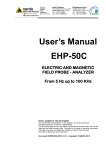
1.2 Inside The SZA-NA(FM)
UP Switch
7-Segment Display
DOWN Switch
DIP Switch
Rotary Switch
(SW8)
TEST Switch
Rotary Switch
(SW9)
SET Switch
(1) Rotary Switches (SW8, SW9)
These switches are used for setting of the SZA-NA(FM).
(2) 7-Segment Display
This display shows an error code representing a trouble when the SZA-NA(FM) detects a
failure. This display is also used for setting of the SZA-NA(FM).
(3) UP Switch
This switch is used to scroll up a list of error codes on the 7-segment display when the
SZA-NA(FM) detects some failures. This switch is also used to select a value in setting of the
SZA-NA(FM).
(4) DOWN Switch
This switch is used to scroll down a list of error codes on the 7-segment display when the
SZA-NA(FM) detects some failures. This switch is also used to select a value in setting of the
SZA-NA(FM).
(5) SET Switch
This switch is used for setting of the SZA-NA(FM).
(6) TEST Switch
This switch is used to test the operation of the SZA-NA(FM) system.
(7) DIP Switch
This switch is used to turn the indication of the 7-segment display upside down. When
installing the SZA-NA(FM) with the suction hole down, set the first microswitch of the DIP
switch to the OFF position. Always leave the second to fourth microswitches in the OFF
position.
2
1700-10330 HA-06-141
Issued: August 4, 2006
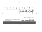
Laser Unit for
Smoke Detection
24 VDC Fuse
Air Flow Sensor
Jumper for Selecting
Contact Logic
Air Intake Fan
for Air Sampling
Connector for Power Supply
of Fan
(8) Laser Unit for Smoke Detection
This unit optically detects smoke.
(9) Air Flow Sensor
This sensor senses a flow of air taken in from the air sampling tube.
(10) Air Intake Fan for Air Sampling
This fan takes in air through the air sampling tube.
(11) 24 VDC Fuse (F3)
This is a 24 VDC-1A fuse for circuit protection.
(12) Jumper for Selecting Contact Logic (J1, J2, J3, J4)
These jumper pins are used to select dry contact output logic for Alarm 3, Alarm 2, Alarm 1,
and System Fault: N/O ("a" contact, normally open) and N/C ("b" contact, normally closed)
Jumper for Alarm 3: J3
Jumper for Alarm 2: J2
Jumper for Alarm 1: J1
Jumper for System Fault: J4
(13) Connector for Power Supply of Fan
This connector is for power of the fan, and it is usually inserted.
When starting up the SZA-NA(FM) in a low temperature environment, the SZA-NA(FM)
may detect and annunciate “Air flow sensor trouble”. In this case, start-up the SZA-NA(FM)
with this connector unplugged, then plug back in later.
3
1700-10330 HA-06-141
Issued: August 4, 2006
2. BASIC WIRING
WARNING
Make sure to observe correct polarity. Use only approved and proper
capacity cable when connecting the SZA-NA(FM).. Failure to follow these
recommendations may cause damage to the SZA-NA(FM) or cause a fire.
If a fuse blows, investigate the wiring and remove the cause of the problem..
Replace fuse only with similar type size and rating..
CAUTION
The earth terminal must be connected. If the earth is not connected,
improper operation may occur.
When making a inlet/outlet hole on the cable hole plate, remove the plate
from SZA-NA(FM) before making the hole. Do not make any holes on main
unit itself. After installation, ensure all debris is removed from and around
the main unit. When performing the insulation test, it is imperative that the
shorting bar in Jumper 7 (J7) and the FG line on the PCB should be
removed. Failure to remove these components at this point may result in
irreparable damage to the unit.
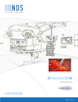
Wiring Example
DC Input Voltage: 24V±10%
Relay Contact Rating: 24VDC, 0.5A
(The wiring example shows the state of the relay contacts before the power source is switched ON.)
Alarm3
Output
Alarm2
Output
Alarm1
Output
System fault
Output
⇒
Power Supply
and
Output monitor
devices
Earth
Clamp filter
(accessory)
⇒
4
1700-10330 HA-06-141
Issued: August 4, 2006
3. INITIAL SYSTEM STATUS AND NORMAL SMOKE DETECTION
STATUS
When turned on, the SZA-NA(FM) initially turns on the POWER indicator, the Air flow fault
indicator, and the System fault indicator on the front panel, and shows the current sensitivity range
on the 7-segment display behind the front panel.
About 20 seconds later, the SZA-NA(FM) becomes ready for detection, turns off the Air Flow Fault
indicator, the System trouble indicator, and the 7-segment display. The SZA-NA(FM) starts normal
monitoring during which, only the POWER indicator is on. The following pages describe the
default settings operation.
4. INDICATIONS AND OPERATION WHEN SMOKE IS DETECTED
4.1 Indications When A Smoke Alarm Occurs
(1) When detecting smoke, the SZA-NA(FM) turns on or blinks all or some of Alarm 1, Alarm 2,
and Alarm 3 indicators according to the optical density of the detected smoke.
Alarm 3: The Alarm 1 indicator turns on orange. The Alarm 2 indicator turns on red.
Alarm 3 indicator blinks red.
Alarm 2: The Alarm 1 indicator turns on orange. The Alarm 2 indicator turns on red.
Alarm 1: The Alarm 1 indicator turns on orange.
The
(2) The buzzer sounds differently in accordance with the optical density of the smoke detected.
Alarm 3: Quick beeps (at short intervals)
Alarm 2: Medium beeps
Alarm 1: Slow and short beeps (at long intervals)
* You can mute the buzzer by employing switch settings found on page 11 of this manual.
(3) The SZA-NA(FM) operates the contact outputs according to the alarm level detected.
4.2 Resetting The Alarm
CAUTION
Find and remove the alarm cause before resetting the SZA-NA(FM),
otherwise the alarm condition will not be reset.
After locating and extinguishing the source of smoke, press the RESET switch on the front panel. If
the smoke density is still over the preset alarm level after the RESET switch is pressed, the
SZA-NA(FM) turns on or blinks the related indicators again.
The SZA-NA(FM) can be set to latch the alarm status until the RESET switch is pressed or
self-reset the alarm status (for automatic recovery) when the smoke optical density drops below the
alarm levels.. By default, the SZA-NA(FM) is factory-set to latch all smoke alarms signals.
5. INDICATIONS AND OPERATION WHEN AN AIR FLOW FAULT IS
DETECTED
5.1 Indications When An Air Flow Fault Occurs (High Air Flow or Low Air Flow
Faults)
(1) When detecting an air flow fault, the SZA-NA(FM) turns on the Air Flow Fault indicator.
Default setting is set to disable detection of a high Air Flow Fault.)
(2) The buzzer in the SZA-NA(FM) makes slow beeps to annunciate an Air Flow Fault.
5
1700-10330 HA-06-141
Issued: August 4, 2006
(3) The SZA-NA(FM) operates the System Fault contact outputs and alerts the related facilities.
(4) The SZA-NA(FM) shows a related error code on the 7-segment display. When other troubles
or faults exist, you can see their error codes by pressing the UP or DOWN switch.
Error code
Fault Name
11
High Air Flow Fault
13
Low Air Flow Fault
5.2 Resetting The Air Flow Fault
You can latch the air flow fault status until the RESET switch is pressed or self-reset the fault
status (for automatic recovery) when the air flow fault is removed. The default setting for the
SZA-NA(FM) is to latch Low Air Flow fault.
6. INDICATIONS AND OPERATION WHEN FAULTS ARE DETECTED
When the SZA-NA(FM) detects an fault, immediately troubleshoot and remove the cause to return
the SZA-NA(FM) to normal monitoring status.
6.1 Monitoring Items
Item
Name of alarm
Description
Laser unit fault
Laser unit trouble
Checks the smoke detecting laser unit for a failure.
Air flow sensor
trouble
Air flow sensor trouble
Checks the air flow sensor for a failure.
Power fault
Supply voltage failure
Detects a DC input voltage lower than 24 VDC.
Test-related error
Manual test error
Detects an error when the manual laser unit test fails.
Automatic test error
Detects an error when the automatic laser unit test (once
a week) fails.
6.2 Indications When A Fault Occurs
(1) When detecting one of the above faults, the SZA-NA(FM) turns on the System Fault indicator.
(2) The buzzer in the SZA-NA(FM) makes slow beeps to alert.
* You can mute the buzzer by setting.
(3) The SZA-NA(FM) operates the System Fault contact outputs and alerts the related facilities.
(4) The SZA-NA(FM) shows a related error code on the 7-segment display. When other faults
exist, you can see their error codes by pressing the UP or DOWN switch.
Error code
Name of alarm
07
Laser unit fault
09
Air flow sensor fault
15
Supply voltage failure
21
Manual test error
25
Automatic test error
6
1700-10330 HA-06-141
Issued: August 4, 2006
6.3 Resetting The Faults
When detecting a manual or automatic test error, press the RESET switch on the front panel of the
SZA-NA(FM).
For other faults or errors, you can set either latching of status until the RESET switch is pressed or
self-resetting of status (for automatic recovery) when the fault disappears. As default, the
SZA-NA(FM) is factory-set to latch fault status.
7. LASER UNIT OPERATION TESTS
7.1 Automatic Laser Unit Test
The SZA-NA(FM) performs an automatic laser unit test periodically once a week (at a preset time
on a preset day of the week). For setting of time and day, see section 7 “SETTINGS."
While the automatic laser unit test is in progress, the SZA-NA(FM) outputs no indication or
beeping.
When the automatic laser unit test fails, the SZA-NA(FM) outputs an error code and beeps. For
more information, see section 6. “INDICATIONS AND OPERATION FAULTS ARE
DETECTED." After checking and repairing, press the RESET switch to return the SZA-NA(FM)
to normal monitoring status.
7.2 Manual Laser Unit Test
CAUTION
In the manual laser unit test, the alarm contact output functions. Set the
related facilities if necessary.
You can manually test the smoke detection laser unit of the SZA-NA(FM).
To start the manual test, keep on pressing the TEST switch on the printed circuit board for 5
seconds or longer or connect the TEST INPUT terminal to the COMMON terminal for 5 seconds
or longer.
While this test is in progress, the SZA-NA(FM) turns on the indicators, activates alerting relays,
and buzzing assuming that it detects a smoke alarm. (You can set to suppress indication and
buzzing.)
When the manual laser unit test fails, the SZA-NA(FM) outputs an error code and beeps. For more
information, see "5. INDICATIONS AND OPERATIONS WHEN THE OTHER ALARM IS
DETECTED." After checking and repairing, press the RESET switch at the front side to return the
SZA-NA(FM) to the normal monitoring status.
8. SETTINGS
WARNING
Call your local HOCHIKI distributor or vendor before changing the setting of
the SZA-NA(FM). The SZA-NA(FM) has been factory-set to satisfy your
environmental requirements. If improperly set, the SZA-NA(FM) may not
work in case of emergency.
7
1700-10330 HA-06-141
Issued: August 4, 2006
8.1 Setting Procedure
Follow the instructions below to set data for the SZA-NA(FM).
Step 1
Press the SET switch for 2 seconds or longer when the SZA-NA(FM) is in normal monitoring status.
The 7-segment display turns on.
Step 2
Select an item you want to set. Set its number by the rotary switches (SW8 and SW9).
Step 3
Select a value for the item on the 7-segment display by pressing the UP or DOWN switch.
Step 4
Press the SET switch. The value on the 7-segment display blinks when the new value is set.
Step 5
Repeat the above steps 2 to 4 to set the other items.
Step 6
After setting all items, press the SET switch for 2 seconds or longer. The 7-segment display goes off.
Step 7
The 7-segment display shows the current sensitivity range for about 20 seconds. Check and make sure the range is
correct during this time period. Then the 7-segment display goes off and the SZA-NA(FM) enters the normal
monitoring status.
8.2 Data Setting
When you set an invalid value by the rotary switches, the 7-segment display shows "- -."
(1) Setting the current time
SW8
SW9
Value range
Initial value
1
0
02 to 89
02
Item name
Year
1
01 to 12
01
Month
2
01 to 31
01
Day
3
00 to 23
00
Hours
4
00 to 59
00
Minutes
Specify the current time here.
To specify a year of 2006, set "06" by the rotary switches.
8
1700-10330 HA-06-141
Issued: August 4, 2006
(2) Setting a sensitivity range
SW8
SW9
Value range
Initial value
2
0
01 to 04
02
Item name
Sensitivity range
Specify a range of smoke detection sensitivity here. Smoke detection sensitivity ranges are
assigned codes as shown below.
01: 0.005 to 0.1%/m (0.002 to 0.03%/ft)
02: 0.01 to 0.2%/m (0.003 to 0.06%/ft)
03: 0.025 to 0.5%/m (0.008 to 0.15%/ft)
04: 0.25 to 5.0%/m (0.08 to 1.55%/ft)
(3) Setting an alarm level
SW8
SW9
Value range
Initial value
Item name
2
1
01 to 20
20
Alarm 3 level
2
01 to 20
16
Alarm 2 level
3
01 to 20
10
Alarm 1 level
Select and specify a 3-step alarm level for smoke density monitoring.
(4) Setting an air flow fault level
SW8
SW9
Value range
Initial value
Item name
2
4
01 to 20
06
Low air flow fault level
5
01 to 20
20
High air flow fault level
Select and specify an air flow fault level in air flow monitoring.
* This setting is invalid when the air flow monitoring function is disabled.
(5) Setting to enable or disable the air flow monitoring function
SW8
SW9
Value range
Initial value
Item name
2
6
00 to 01
01
Low Air Flow Fault monitoring function
7
00 to 01
00
High Air Flow Fault monitoring function
Set the air flow monitoring function to enable or disable. The meaning of the setting is as
follows: Initially, the high air flow fault monitoring function is disabled.
00: Disabled
01: Enabled
(6) Setting an alarm delay time
SW8
SW9
Value range
Initial value
Item name
3
0
00 to 60
00
Alarm 3 delay time
1
00 to 60
00
Alarm 2 delay time
2
00 to 60
00
Alarm 1 delay time
Specify a time period (in seconds) during which smoke detection alarm level is reached before
the SZA-NA(FM) annunciates that an alarm has occurred. When "00" is set, the SZA-NA(FM)
outputs an alarm immediately when detecting it.
9
1700-10330 HA-06-141
Issued: August 4, 2006
(7) Setting an air flow fault delay time
SW8
SW9
Value range
Initial value
Item name
3
3
00 to 60
10
Low air flow fault delay time
4
00 to 60
10
High air flow fault delay time
Specify a time period (in seconds) during which an air flow fault is reached before the
SZA-NA(FM) annunciates that a fault has occurred. When "00" is set, the SZA-NA(FM)
outputs a fault immediately when detecting it.
(8) Setting the delay time of Other faults
SW8
SW9
Value range
Initial value
5
00 to 60
10
Not Used
6
00 to 60
10
Supply voltage alarm delay time
3
Item name
Specify a time period (in seconds) during which the above faults continue before the
SZA-NA(FM) annunciates that a fault has occurred. When "00" is set, the SZA-NA(FM)
outputs a fault immediately when detecting it.
(9) Setting to latch or self-reset the alarm status
SW8
SW9
Value range
Initial value
Item name
4
0
00 to 01
01
Latching or self-resetting Alarm 3
1
00 to 01
01
Latching or self-resetting Alarm 2
2
00 to 01
01
Latching or self-resetting Alarm 1
You can specify latching the alarm status until the RESET switch is pressed or self-resetting
the alarm status (for automatic recovery) when the alarm level drops below the threshold. As
the default, the SZA-NA(FM) is factory-set to latch all smoke alarms.
00: Self-resets the alarm status.
01: Latches the alarm status
(10) Setting to latch or self-reset the air flow and other faults
SW8
SW9
Value range
Initial value
Item name
4
3
00 to 01
00
Latching or self-resetting the low air flow fault
4
00 to 01
00
Latching or self-resetting the high air flow fault
5
00 to 01
00
Latching or self-resetting the other faults
You can specify latching of the alarm status until the RESET switch is pressed or
self-resetting of the alarm status (for automatic recovery) when the fault disappears. As default,
the SZA-NA(FM) is factory-set to non-latching.
00: Does not Latch the fault status.
01: Latches the fault status.
10
1700-10330 HA-06-141
Issued: August 4, 2006
(11) Setting to turn on or off the alarm indication while an alarm or fault is delayed
SW8
SW9
Value range
Initial value
Item name
5
0
00 to 01
00
Turns on the Alarm 3 indicator while Alarm 3 is
delayed.
1
00 to 01
00
Turns on the Alarm 2 indicator while Alarm 2 is
delayed.
2
00 to 01
00
Turns on the Alarm 1 indicator while Alarm 1 is
delayed.
3
00 to 01
00
Turns on the Air Flow Fault indicator while the
low air flow fault is delayed.
4
00 to 01
00
Turns on the Air Flow Fault indicator while the
high air flow fault is delayed.
5
00 to 01
00
Turns on the Power Failure indicator while the
AC power failure alarm is delayed.
6
00 to 01
00
Turns on the System Failure indicator while the
supply voltage alarm is delayed.
Specify the status of indicators on the front panel while smoke and faults are delayed. Specify
ON or OFF for the indicators. As default, the SZA-NA(FM) is factory-set to turn off all of
these indicators.
00: ON
01: OFF
* When the AC Power Failure indicator is set to OFF, and the power failure alarm is delayed,
the POWER indicator remains ON.
(12) Buzzer setting
SW8
SW9
Value range
Initial value
Item name
6
0
00 to 01
01
Activates the buzzer when Alarm 3 occurs.
1
00 to 01
01
Activates the buzzer when Alarm 2 occurs.
2
00 to 01
01
Activates the buzzer when Alarm 1 occurs.
3
00 to 01
01
Activates the buzzer when a low air flow fault
occurs.
4
00 to 01
01
Activates the buzzer when a high air flow fault
occurs.
5
00 to 01
01
Activates the buzzer when the other faults
occur..
Specify turning on or off the built-in buzzer when smoke detection and other faults occur.
Specify 00 (ON) or 01 (OFF) for each buzzer. As default, the SZA-NA(FM) is factory-set to
turn on the buzzer for all smoke detection and other faults.
00: OFF (Deactivates the buzzer.)
01: ON (Activates the buzzer.)
(13) Setting to enable or disable the automatic laser unit test
SW8
SW9
Value range
Initial value
7
0
00 to 01
01
Item name
Enables the automatic laser unit test.
Specify enabling or disabling the automatic laser unit test. Specify 00 to disable the automatic
laser unit test or 01 to enable the automatic laser unit test. As default, the SZA-NA(FM) is
factory-set to enable the automatic laser unit test.
00: Disable the automatic test.
01: Enable the automatic test.
11
1700-10330 HA-06-141
Issued: August 4, 2006
(14) Setting a day for automatically implementing the laser unit test
SW8
SW9
Value range
Initial value
7
1
01 to 07
01
Item name
Date of automatically implementing the laser
unit test
Specify a day for automatically implementing the laser unit test. Days of the week are
assigned unique codes as shown below. As default, the SZA-NA(FM) is factory-set to
implement the automatic laser unit test on Monday.
01: Monday
02: Tuesday
03: Wednesday
04: Thursday
05: Friday
06: Saturday
07: Sunday
* This setting is invalid when the implementation of the automatic laser unit test is disabled.
(15) Setting the time of automatically implementing the laser unit test
SW8
SW9
Value range
Initial value
Item name
7
2
00 to 23
10
Time (hours) of automatically implementing the
laser unit test
3
00 to 59
00
Time (minutes) of automatically implementing
the laser unit test
Specify the time of automatically implementing the laser unit test. As default, the
SZA-NA(FM) is factory-set to implement the automatic laser unit test at 10:00 am.
* This setting is invalid when the implementation of the automatic laser unit test is disabled.
(16) Setting to enable or disable fault indications for the manual laser unit test
SW8
SW9
Value range
Initial value
7
4
00 to 01
01
Item name
Enables fault indications for the manual laser
unit test.
Specify enabling or disabling fault indications (LED indication, beeping, etc.) in the manual
laser unit test. Specify 00 not to implement fault indications (LED indication, beeping, etc.) in
the manual laser unit test, or 01 to implement the fault indications. As default, the
SZA-NA(FM) is factory-set to enable the fault indications.
00: Disable the fault indications for the manual test.
01: Enable the fault indications for the manual test.
(17) Setting to enable or disable output contacts
SW8
SW9
Value range
Initial value
8
0
00 to 01
00
Item name
Enable or disable output contacts.
Specify to enable or disable output contacts when a smoke alarm or system fault occurs during
installation or maintenance of the SZA-NA(FM). This function controls the operation of the
output relay contacts. The setting values are 00 and 01. As default, the SZA-NA(FM) is
factory-set to enable alarm and fault output contacts.
00: Outputs enabled..
01: Outputs disabled.
12
1700-10330 HA-06-141
Issued: August 4, 2006
(18) Setting to activate the buzzer when output contacts are disabled
SW8
SW9
Value range
Initial value
8
1
00 to 01
00
Item name
Activates the buzzer when output contacts are
disabled.
Setting to activate the buzzer when output contacts are disabled. In this case, the buzzer beeps
at short intervals for about 30 seconds. The setting values are 00 and 01. As default, the
SZA-NA(FM) is factory-set to deactivate the buzzer.
00: OFF (Deactivates the buzzer.)
01: ON (Activates the buzzer.)
* This setting is invalid when the output contacts are enabled.
(19) Setting to enable or disable calculation of moving average deviations
SW8
SW9
Value range
Initial value
8
2
00 to 01
01
Item name
Calculates a moving average.
This function calculates a moving average of analog values for 2 seconds and monitors the
deviation of the analog value from the moving average. This ensures that a transient analog
value change does not significantly affect the monitoring of smoke detection or air flow. The
setting values are 00 and 01. As default, the SZA-NA(FM) is factory-set to calculate a moving
average of analog values.
00: Enable the calculation.
01: Disable the calculation.
*(20) Setting to clear the event history
SW8
SW9
Value range
Initial value
8
3
00 to 01
00
Item name
Self-resets the event history.
Specify to keep or self-reset the event history in the built-in memory.
00 and 01.
00: Does not clear the event history.
01: Clears the event history.
The setting values are
*(21) Setting to clear the analog history
SW8
SW9
Value range
Initial value
8
4
00 to 01
00
Item name
Clears the analog history.
Specify to keep or self-reset the analog history in the built-in memory.
00 and 01.
00: Does not clear the analog history.
01: Clears the analog history.
The setting values are
(22) Setting to initialize the system setting
SW8
SW9
Value range
Initial value
8
5
00 to 01
00
Item name
Initializes the system setting.
Specify whether you want to initialize the system settings stored in the built-in non-volatile
memory (to the default setting). This function initializes parameter values to the default values.
The setting values are 00 and 01.
00: Does not initialize the system setting.
01: Initialize the system setting.
* Note: Requires additional hardware and software to read event history.
13
1700-10330 HA-06-141
Issued: August 4, 2006
(23)
Setting for External Power Fault input monitoring
SW8
SW9
Value range
Initial value
8
6
00 to 01
00
Item name
External Trouble input logic (NO or NC).
If desired, the SZA-NA(FM) can monitor power faults on a power supply with battery backup
using dry relay contacts. Specify the External Fault input contact logic NO or NC. The
setting values are 00 and 01. As default, the SZA-NA(FM) is factory-set to "External Fault
input logic = NO."
00: Monitors NO contacts.
01: Monitors NC contacts.
9. CONTACT OUTPUT STATUS
9.1 Contact Output Status In Normal Monitoring
Jumper connection for
selection of contact logic
Alarm 3•2•1 output
System Fault output
NO
Closed for alarm and Normally-open
Closed for system alarm and
Normally-open
NC
Open for alarm and Normally-closed
Open for system alarm and
Normally-closed
9.2 Contact Output Status When Power to the SZA-NA(FM) is Lost
Jumper connection for
selection of contact logic
Alarm 3•2•1 output
System Fault output
NO
Open
Closed
NC
Closed
Open
14
1700-10330 HA-06-141
Issued: August 4, 2006
10. SPECIFICATION
Item
Specification
Model
SZA-NA(FM)
Power supply
24 VDC ± 10%
Working Voltage Range
19.4 VDC ~ 29.0 VDC
Sensitivity range
Selectable from four sensitivity ranges below
Sensitivity 1: 0.005 to 0.1%/m (0.002 to 0.03%/ft)
Sensitivity 2: 0.01 to 0.2%/m (0.003 to 0.06%/ft)
Sensitivity 3: 0.025 to 0.5%/m (0.008 to 0.15%/ft)
Sensitivity 4: 0.25 to 5.0%/m (0.08 to 1.55%/ft)
Current output
4-20mA DC output (Receiving resistance: 100 Ω or less)
Contact output
Alarm 1 output, Alarm 2 output, Alarm 3 output, and System Fault output
Contact capacity
24 VDC, 0.5A or less (each contact output)
Contact output logic
NO ("a" contact) or NC ("b" contact) selectable by a jumper
External power fault monitoring
input
NO ("a" contact) or NC ("b" contact) selectable by system setting
Wires used
Heat-resistant shielded wires
Materials
Body and panel: Steel 22 Gage, baked painting
Display operation panel: Steel 20 Gage
Colors
Body and panel: Munsell 2.5Y9/1 or equivalent
Display panel: Munsell 5Y6/0.5 or equivalent
Weight
Approx. 8 lbs.
Dimensions
12 ½” (W) × 8 7/8” (H) × 4” (D)
Operating temperature
-10°C to +50°C
Installation
Indoor (Non-condensing)
Accessory
Dedicated flexible pipe
0.5A or less
(mm)
11. IF YOU HAVE ANY QUESTIONS, CONTACT:
Hochiki America Corporation
7051 Village Drive, Suite 100
Buena Park, CA 90621-2268 USA
Tel (714) 522-2246
Fax (714) 522-2268
Technical Support: (800) 845-6692
15
1700-10330 HA-06-141
Issued: August 4, 2006