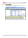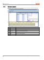
1
USER MANUAL © Copyright Reserved Autonics Co., Ltd. iii Preface Preface Thank you for purchasing an Autonics product. This user manual contains information about the product and its proper use, and should be kept in a place where it will be easy to access. iv © Copyright Reserved Autonics Co., Ltd. User Manual Guide User Manual Guide This user manual contains information about the product and its proper use, and should be kept in a place where it will be easy to access. Please familiarize yourself with the information in this manual before using the product. This manual provides detailed information on the product's features. It does not offer any guarantee concerning matters beyond the scope of this manual. This manual may not be edited or reproduced in either part or whole without permission. A user manual is not provided as part of the product package. Visit www.autonics.com to download a copy. The manual's content may vary depending on changes to the product's software and other unforeseen developments within Autonics, and is subject to change without prior notice. This manual is produced based on DAQMaster 1.5.3 version. 5 © Copyright Reserved Autonics Co., Ltd. v User Manual Symbols User Manual Symbols Symbol Description Supplementary information for a particular feature. Failure to follow instructions can result in serious injury or death. Failure to follow instructions can lead to a minor injury or product damage. An example of the concerned feature's use. ※1 vi Annotation mark. © Copyright Reserved Autonics Co., Ltd. Table of Contents Table of Contents Preface ......................................................................................................................... iv User Manual Guide ........................................................................................................ v User Manual Symbols ................................................................................................... vi Table of Contents .......................................................................................................... vii 1 2 DAQMaster Overview.................................................................................. 9 1.1 Overview ............................................................................................................ 9 1.2 Features .......................................................................................................... 10 Installing the Program .............................................................................. 11 2.1 System Requirements ..................................................................................... 11 2.2 Preparations .................................................................................................... 11 2.2.1 2.2.2 2.3 Start and Exit ................................................................................................... 16 2.3.1 2.3.2 2.4 3 Start ............................................................................................................ 16 Exit ............................................................................................................. 16 DAQMaster Screen Layout .............................................................................. 17 2.4.1 2.4.2 2.4.3 2.4.4 2.4.5 2.4.6 2.4.7 2.4.8 2.4.9 2.4.10 2.5 Installation Folder Structure ....................................................................... 15 Uninstalling the Program ............................................................................ 16 Menu .......................................................................................................... 18 Toolbar........................................................................................................ 20 Supported Device List (Docking Screen) ................................................... 21 Project ........................................................................................................ 21 I/O List (Docking Screen) ........................................................................... 22 My System.................................................................................................. 23 DAQ List ..................................................................................................... 24 Message ..................................................................................................... 24 DAQ WorkSpace ........................................................................................ 24 Property ...................................................................................................... 26 Runtime Screen Library ................................................................................... 32 Getting Started .......................................................................................... 35 3.1 Supported Device List - Selecting a Device ..................................................... 36 3.2 Setting RS-232, TCP/IP ................................................................................... 39 3.2.1 3.2.2 RS-232C..................................................................................................... 39 TCP/IP ........................................................................................................ 40 3.3 Adding a Unit to My System ............................................................................ 41 3.4 Scan Unit ......................................................................................................... 45 3.5 Adding an I/O to the I/O List ............................................................................ 47 3.6 DAQ List .......................................................................................................... 50 3.7 Adding from DAQ List to Runtime Screen Library ........................................... 51 3.7.1 3.7.2 3.7.3 3.7.4 Grid............................................................................................................. 52 Panel .......................................................................................................... 54 Line Graph.................................................................................................. 55 Bar Graph ................................................................................................... 62 © Copyright Reserved Autoonics Co., Ltd. vii Table of Contents 3.7.5 3.7.6 Color Map Graph ........................................................................................ 66 Gauge Graph .............................................................................................. 70 3.8 Connection ...................................................................................................... 73 3.9 Running the Program ...................................................................................... 75 3.10 Logging ............................................................................................................ 77 3.11 Saving Project ................................................................................................. 78 3.12 Opening a Project ............................................................................................ 80 3.12.1 Open Project .............................................................................................. 80 3.12.2 Open Project List: ....................................................................................... 80 3.13 4 5 Modbus Map Table Report .............................................................................. 81 Changing Program Language ..................................................................83 4.1 Change Language ........................................................................................... 83 4.2 Modifying and Adding Languages.................................................................... 84 Data Analysis .............................................................................................87 5.1 Screen Layout ................................................................................................. 88 5.1.1 5.1.2 5.1.3 5.1.4 5.1.5 5.1.6 5.2 Analyzing Data ................................................................................................ 92 5.2.1 5.2.2 6 Opening Data Files ..................................................................................... 92 Add Analysis Screen .................................................................................. 92 Special Features ........................................................................................95 6.1 KONICS ........................................................................................................... 95 6.1.1 6.1.2 6.2 KRN50 ........................................................................................................ 95 KRN100 ...................................................................................................... 99 ModBus Master ............................................................................................. 102 6.2.1 viii Menu........................................................................................................... 89 Toolbar ........................................................................................................ 90 File List ....................................................................................................... 90 DAQ List ..................................................................................................... 90 Grid ............................................................................................................. 91 Graph.......................................................................................................... 91 ModBus Master Communication and CRC Calculation ........................... 102 © Copyright Reserved Autonics Co., Ltd. 1 DAQMaster Overview 1 DAQMaster Overview 1.1 Overview DAQMaster is a comprehensive device management program that can be used with Autonics thermometers, panel meters, pulse meters, and counters, etc and with Konics recorders, indicators. DAQMaster provides GUI control for easy and convenient management of parameters and multiple device data monitoring. © Copyright Reserved Autonics Co., Ltd. 9 1 DAQMaster Overview 1.2 Features DAQMaster has the following features: (1) Multiple Device Support Simultaneously monitor multiple devices and set parameters. Simultaneously connect units with different addresses in a single device. Multiple RS-233 ports are available for communications using Modbus remote terminal unit. (2) Device Scan In cases of multiple units (with different addresses) connected together, the unit scan function automatically searches for units. (3) Convenient User Interface Freely arrange windows for data monitoring, properties, and projects. Saving a project also saves the screen layout. (4) Project Management You can save added device information, data monitoring screen layouts, and I/O source selection as project files. Opens project files to load the saved settings. Provides a project list for simple and easy project file management. (5) Monitoring Data Log When monitoring, data log files can be saved as either DAQMaster data files (.ddf) or CSV (.csv) files. Open files saved in .csv format directly from Microsoft Excel. Define log data file naming/saving rules and destination folders to make file management convenient. (6) Data Analysis Performs grid and graph analyses of .ddf data files using DAQMaster's data analysis feature. Saves grid data as .rtf, .txt, .html, or .csv files in Data Grid. (7) Print Modbus Map Table Report Print address map reports of registered Modbus devices. Modbus map table reports can be saved as .html and .pdf formats. (8) Multilingual Support Supports Korean, English, Japanese, Simplified Chinese. To add a different language, modify the files in the Lang folder, rename, and save. (9) Script Support Uses the Lua Script language and deals with different I/O processes for individual devices. 10 © Copyright Reserved Autonics Co., Ltd. 2 Installing the Program 2 Installing the Program 2.1 System Requirements 2.2 Item Requirements Processor IBM PC compatible computer with Intel Pentium 3 or above Operating system Microsoft Windows 98/NT/XP/Vista/Windows 7 RAM 256 MB or more Hard disk More than 1 GB of free hard disk space VGA 1024 X 768 or higher resolution display Others Communication port: RS-232 serial port, USB to 232 Preparations 1st Download DAQMaster program at Autonics’ web page(www.autonics.com). 2nd Close all programs before you start DAQMaster installation. Double-click DAQMaster setup.exe to start installation. 3rd Installer Language window appears. Select the language and click OK button. DAQMaster supports English, Japanese, Korean and Simplified Chinese. © Copyright Reserved Autonics Co., Ltd. 11 2 Installing the Program 4th Click Next in the installation welcome window. 5th Choose Install Location window appears. Default installation path is C:\Program Files\DAQMaster. 12 © Copyright Reserved Autonics Co., Ltd. 2 Installing the Program 6th Click Install button to choose the default path for installation. Click Browse button to change the installation path. In the Browse Folder window, select the desired destination folder and then click OK to start installation. 7th Installation progress is displayed in the status window as follows. © Copyright Reserved Autonics Co., Ltd. 13 2 Installing the Program 8th Installation Complete window appears after installation is completed. If the check box in the Installation Complete window is checked, DAQMaster runs upon completion of installation. You can now run DAQMaster by double-clicking the DAQMaster icon on the desktop. When running the program for the first time, the initial screen displays the following. 14 © Copyright Reserved Autonics Co., Ltd. 2 Installing the Program 2.2.1 Installation Folder Structure This section explains the folder structure created when you installed DAQMaster. After DAQMaster installs completely, folders are created as below. The program and all relevant documents are stored in these folders. If you selected the default installation path during installation, a DAQMaster folder is created under [C:\Program Files] as a subfolder. If you selected a new destination folder, DAQMaster folder is located in that folder. (1) Device folder Device folder contains the device information files (*.dev), which can be monitored and set with DAQMaster. When the program is executed, the files in this folder automatically add related devices to the program. If devices are added or upgraded after the program is installed, copy the device information file and put it into this folder. The list of available devices will be updated. However, if a communication related function is added or modified, it also changes the contents of the [plug-in] folder. Therefore changes may or may not be applied depending on the level of upgrade. (2) Lang folder The language information files (*.lang) available in this program are contained here. The program reads all files in the folder and automatically adds them to the program when it runs. The language information files are written in a text file format, so you can modify and add text using XML Notepad. Korean, English, Japanese, Simplified Chinese language files are in this folder by default. (3) Plug-in folder This folder contains core library files (*.dll) for ModBus communications as well as runtime screen files (*.rpu). The [prop] folder under the [plug-in] folder stores library files that have special functions for each specific device. © Copyright Reserved Autonics Co., Ltd. 15 2 Installing the Program 2.2.2 Uninstalling the Program There are procedures to uninstall DAQMaster. Select Start > Program > DAQMaster > Uninstall or Start > Setting > Control Panel > Add/Remove a Program > DAQMaster. If you select Remove, a confirmation window will appear. Click Yes to remove DAQMaster from the computer. 2.3 Start and Exit 2.3.1 Start Double-click DAQMaster on the desktop or select Start > Program > DAQMaster to start DAQMaster. 2.3.2 Exit Click X button on the top right corner of the screen, or select File > Exit on the menu bar to end the program. Projects are not saved automatically. Please make sure you save the project before you exit. . 16 © Copyright Reserved Autonics Co., Ltd. 2 Installing the Program 2.4 DAQMaster Screen Layout The program screen is divided into sections as shown in the preceding screenshot and each section is composed of the following items. NO. Item Description ① Menu ② Toolbar ③ Supported device list Displays a list of devices supported by DAQMaster. ④ Project Shows the basic information of the current project. ⑤ I/O List Displays parameter items of devices added to My System. ⑥ My System ⑦ DAQ List Displays DAQMaster menus by category. If you select a menu, submenus appear. Displays commonly used menus. Click one time to execute their functions. Shows list and connection status of devices connected to DAQMaster. Shows added parameter items in I/O List. Records events. ⑧ Message It displays communication connection and disconnection, errors. ⑨ DAQ WorkSpace ⑩ Property ⑪ Runtime Library © Copyright Reserved Autonics Co., Ltd. Displays added UI items in RunTime Screen. Allows checking and modification of information for items in Project, My System, DAQ List and setting unit parameters. Displays screen library for data monitoring. 17 2 Installing the Program 2.4.1 Menu (1) File New Project: Creates a new project. Open Project List: Opens a project from the project list. Open Project: Opens a saved project. Save Project: Saves the project you are working on. Save Project As: Saves the project as a file name. Exit: Ends the program. (2) View Select to display screens while the program is running. (3) Run 18 Connect/Disconnect: Connects or disconnects the device and communication. Run/stop: Starts or stops monitoring data in the connected devices. Start/stop logging: Saves or stops logging currently monitored data. © Copyright Reserved Autonics Co., Ltd. 2 Installing the Program (4) Tools Time Display: Displays monitoring time. Data Analysis: Runs the data analysis program. Allows analysis of DAQMaster data file (*.ddf). Language: Changes the program language. (5) Window Chooses a screen align option from Horizontal Align and Vertical Align and aligns screens when multiple runtime screens (Grid, Panel, Line Graph, Bar Graph, etc) are open. (6) Help Help: Starts the help file. Check Update: Checks and automatically updates the latest version on the update server. About DAQMaster: Check the program version. © Copyright Reserved Autonics Co., Ltd. 19 2 Installing the Program 2.4.2 Toolbar No. Item Description ① New project Creates a new project. ② Open Project List Opens a project from project list. ③ Open Project Opens a saved project. ④ Save Project Saves the project you are working on. ⑤ Disable -. ⑥ Connect Starts communications when a device is added and ready for communication. Enables when communications are connected. ⑦ Run Reads I/O parameter data according to the defined interval. Enables when communications are exchanged. Saves the log data temporarily in memory when ⑧ Log logging starts, and permanently saves the data when the logging stops. Allows log data to be saved as a DAQMaster data file (*.ddf) or a CSV file (*.csv). ⑨ 20 Layout Default: Sets the docking screen to the program start default. Runtime: Activates only runtime screen. Displays hidden docking screens by selecting the View menu. © Copyright Reserved Autonics Co., Ltd. 2 Installing the Program 2.4.3 Supported Device List (Docking Screen) Supported Device List shows list of devices supported by DAQMaster. The Supported Device List will be updated continuously. 2.4.4 Project Project saves runtime screen information and I/O source. Allows you to work in previously used environments again. In Property, you can change general information, data file, log data schedule, project open of project. For more information, refer to '2.4.10 Property'. © Copyright Reserved Autonics Co., Ltd. 21 2 Installing the Program 2.4.5 I/O List (Docking Screen) I/O List shows parameters you can monitor for devices added to My System. I/O List appears depending on connected devices. To monitor units of the connected device, parameter sources displayed in I/O List should be added to the DAQ List. Displays parameter sources added to DAQ List in gray. I/O source cannot be added to DAQ List when the Status is Run. 22 © Copyright Reserved Autonics Co., Ltd. 2 Installing the Program 2.4.6 My System My System displays devices and units added from the device list in a tree structure. You can also check and configure connection status. You can add, change or delete devices and units (addresses) added to My System. RS-232: Allows modification of RS-232 related communications in Property when disconnecting. ModBus Master: Allows property modification related to ModBus Master protocol while disconnected. Device (TK4): Allows you to see connected device information. Unit (1): Allows read and write of parameters as well as check the reading process while connected. Connects a device to multiple communications ports as displayed in following image. © Copyright Reserved Autonics Co., Ltd. 23 2 Installing the Program 2.4.7 DAQ List DAQ List is a list of I/O sources that will be communicated. DAQ List displays the number of I/O sources by signal type on the left, and rearranges them on the right when selected. Signal types: AI (Analogue Input), AO (Analogue Output), DI (Digital Input), DO (Digital Output). DAQ List cannot be added to a runtime screen when the Status is Run. 2.4.8 Message Records events. (It is not supported yet.) 2.4.9 DAQ WorkSpace Displays added UI screen (Grid, Panel, Line Graph, Bar Graph, Color Map Graph, Gauge Graph) in RunTime Screen. 24 © Copyright Reserved Autonics Co., Ltd. 2 Installing the Program To add or delete DAQ WorkSpace or change DAQ WorkSpace name, click pull-down icon (▼) on the upper right of DAQ WorkSpace. The below two DAQ WorkSpaces are changed name as ‘Gauge and Color map’ and ‘Line graph’. © Copyright Reserved Autonics Co., Ltd. 25 2 Installing the Program 2.4.10 Property The Property window allows item checking and modification of Project, My System and DAQ List. There are check-only items and modifiable items. Modifiable items are displayed as edit type, combo box type, run type and mixed edit/combo type. (1) Edit type Allows number or text entry. Input range (if applicable) is displayed at the bottom. (2) Combo box type Click the combo button on the right to see a list of items to select. (3) Run type Click [...] button on the right to start the relevant function. (4) Mixed edit-combo type Allows number or text entry (within the range specified at the bottom) and selection of a value from the list. Items out of range can only be selected from the combo box list. 26 © Copyright Reserved Autonics Co., Ltd. 2 Installing the Program 2.4.10.1 Project Properties Clicking Project Name (initial status: Noname) allows you to set and enter general (project name, company, worker, description), data file (data folder, data file creation rules, etc.), log data schedule (log data schedule, active schedule), and project open (run mode, layout). (1) General You can enter project name, company, worker, description for project management. (2) Data File Designates the folder to save log data and log data file’s creation rules when it is created automatically. Log data is available to save as *.csv or *.ddf file type. Data Folder: Designates the folder to save project data. Data file creation rules: Designates data file’s creation rules. © Copyright Reserved Autonics Co., Ltd. 27 2 Installing the Program (3) log data schedule Saves log data when the set scheduled time automatically. Log Data Schedule: Sets log data save time. No ① Description Displays scheduled log data items. You can delete the scheduled item by checking the left check box and clicking ⑧ button. ② Adds log data schedule items. ③ Designates log data name. The file name of data file creation rule is displayed next to the data name. ④ Designates start time. ⑤ Designates end time. ⑥ Designates split save time. When you set 1 hour 30 minutues, it saves the file for 1 hour 30 min. and creates another file and saves it. ⑦ Designates repetition day of week. ⑧ Saves or deletes the set items. ⑨ Checks log data schedule items. Active Schedule: Designates whether to active log data schedule. (4) Project Open Run Mode: Sets run mode when opening the saved project file. 28 Layout : Designates the screen layout (default, runtime, current layout) when opening the project. © Copyright Reserved Autonics Co., Ltd. 2 Installing the Program 2.4.10.2 My System Properties (1) RS232 Click RS-232 in My System to modify Name in RS-232 general properties. You can also modify Port List Detect, Port, Baudrate, Parity, Stop Bits, ByteSize, HW, SW, DTR, RTS in Config. (2) Modbus Master You can modify Name in ModBus Master general properties by clicking ModBus Master in My System. You can also modify Mode and Timeout in Config. (3) Device (TK4) Click a device (TK4) in My System to see basic device information in the Property window. © Copyright Reserved Autonics Co., Ltd. 29 2 Installing the Program (4) Address (1) Click the device address (1) in My System to see detailed device information. You can also change Unit Name and set Repeat Interval. You can check and modify device parameters by reading parameters while connected. 2.4.10.3 DAQ List Properties If you select items that were added from I/O List for communication, the Property window displays item information. You can change Tag Name, Decimal Point and Unit of an item. 30 © Copyright Reserved Autonics Co., Ltd. 2 Installing the Program 2.4.10.4 Runtime Properties You can desigante added runtime screen (Grid, Line Graph, Bar Graph, Color Map Graph, Gauge Graph) name, update interval, and the others. You can modify the name of the Grid in Run UI general properties by clicking Grid on the project's runtime screen. You can also modify Update Interval time in Config. (Default: 1,000 ms.) © Copyright Reserved Autonics Co., Ltd. 31 2 Installing the Program 2.5 Runtime Screen Library Double-click UI item in Runtime Screen Library and the item is added in DAQ WorkSpace. Runtime Screen Library is a list of runtime screens for data monitoring. Runtime screens support Grid, Panel, Line Graph, Bar Graph, Color Map Graph and Gauage Graph. You can open multiple screens at the same time for monitoring. Information such as screen position, screen size and I/O source is saved when saving the project. (1) Grid (2) Panel 32 © Copyright Reserved Autonics Co., Ltd. 2 Installing the Program (3) Line Graph (4) Bar Graph © Copyright Reserved Autonics Co., Ltd. 33 2 Installing the Program (5) Color Map Graph (6) Gauge Graph 34 © Copyright Reserved Autonics Co., Ltd. 3 Getting Started 3 Getting Started On a default layout screen, you generally work from left to right. The basic work order is as follows: 1st Select a device from the supported device list on the top left and add it to My System. 2nd Select a device from My System and add a relevant unit (address). 3rd From the top left I/O List, add I/O for monitoring to DAQ List at the bottom. 4th Select a monitoring screen from runtime screen library on the top right. 5th Drag an I/O source from DAQ List and drop it onto the runtime screen. 6th Configure RS-232 or Modbus TCP environment. 7th Connect (you can read and set the device parameters). 8th Run (data file logging is available). © Copyright Reserved Autonics Co., Ltd. 35 3 Getting Started 3.1 Supported Device List - Selecting a Device For example: TK4 (Address 3) is connected to RS-232 Port 1. First, select the device to communicate with from the Supported Device List. The Supported Device List (docking screen) is a list of devices supported by DAQMaster. You can only communicate with listed devices.(The Supported Device List will be updated continuously). Below is the example screen for the currently supported devices(as of November.2012). 36 © Copyright Reserved Autonics Co., Ltd. 3 Getting Started When a device is selected, you can see basic information about the device in Property window as follows. If you click or double-click the device manufacturer's (AUTONICS or KONICS) expand button (+), the supported device list will appear. Select the device you want to add to My System (Autonics Temperature Controller TK4). Double-click or mouse right-click the selected device and select Add to My System to add the device. Refresh: Updates Supported Device List when device files (*.dev) are added. Add to my system: Adds device to communicate with to My System. Expand all: Shows the list of all supported devices. Collapse all: Hides the list of all supported devices. © Copyright Reserved Autonics Co., Ltd. 37 3 Getting Started Double-click RS-232 or TCP/IP on the new DAQ interface, or select it and click OK. (TK4 supports RS-232 communication and it displays only RS-232.) You can modify the configuration of the added RS 232 or TCP/IP in properties. In case the model supporting TCP/IP, it displays TCP/IP. If My System has added devices, you can see added RS-232-COM1 on the Added DAQ Interface. 38 © Copyright Reserved Autonics Co., Ltd. 3 Getting Started 3.2 Setting RS-232, TCP/IP 3.2.1 RS-232C Set up RS-232 for communication. Select RS-232 in My System and check Property window. Property window displays information about the communication port currently in use. If you want to change the name in My System, modify Name in Property window. The items are under Config. Item Port List Detect Port Baudrate Parity Description Fix Init List Auto Detect Gets computer's communication port list at the point when RS-232 is added, saves it to the Port List and then fixes it. If the computer's port list (such as USB 232) has changed, this rearranges the list. Shows choice of connectable COM Ports. Designate the connected COM Port. 1,200, 2,400, 4,800, 9,600, 19,200, 38,400, 57,600, 115,200 bps Allows communication parity selection. (none, odd, even, mark, space) Stop Bits Selects Stop Bits. (1, 1.5, 2) Byte Size Selects Byte Size. (5, 6, 7, 8) Hw None, RTS/CTS Sw None, XON/XOFF DTR Disable, enable, toggle RTS Disable, enable, handshake, toggle © Copyright Reserved Autonics Co., Ltd. 39 3 Getting Started 3.2.2 TCP/IP Set up TCP/IP for communication. Select TCP/IP in My System and check Property window. Property window displays information about the communication port currently in use. If you want to change the name in My System, modify Name in Property window. The items are under Config. Item Description Socket Client Sets as client mode (when connecting KRN100) Type Server Sets as server mode. Address Enters the designated IP Address from the main device. Port Port Connection Timeout Connection Timeout Non Blocking Client Type After transmission, next transmission is available to process without response. After transmission, this mode waits for response. After Blocking receiving the response, next transmission is available to process. At ModBus Master property, set Mode of Config as ModBus TCP. 40 © Copyright Reserved Autonics Co., Ltd. 3 Getting Started 3.3 Adding a Unit to My System My System displays device and communication interfaces added from the supported device list in a tree structure. It also displays connection status, and you can add, change and delete device units (addresses). By selecting an item, you can set or modify it in Property window. Selecting TK4 device enables Add button. To add a unit(address), click the Add button on the tab or right-click on mouse to select Add. © Copyright Reserved Autonics Co., Ltd. 41 3 Getting Started Select address (number 3) set to TK4 device. Double-click or use ‘>’ button to add, then click OK button. 42 © Copyright Reserved Autonics Co., Ltd. 3 Getting Started You will see the unit (address: 3) added under the device in My System. If you want add more than one of the same type of device, click Add button. (Up to 99 devices can be added.) Selecting the unit address (3) enables Change button. To change the unit address, click the Change button on the tab or right-click on mouse to select Change. © Copyright Reserved Autonics Co., Ltd. 43 3 Getting Started If you click Change button, the current address (3) highlights in yellow. Select a new address and click OK to change the unit address. Unit (address) cannot be deleted, changed or added while the Status is Connect. 44 © Copyright Reserved Autonics Co., Ltd. 3 Getting Started 3.4 Scan Unit Scan Unit feature scans multiple connected device units. You can check the detected units and add them to My System by using this feature. 1st Add TK4 device and configure RS-232 environment as below. And then connect. 2nd When connected, select TK4 device, and right-click to select Scan Device. 3rd If you select Scan Device menu, the following Unit Scan dialog appears. 4th Set an address range to scan and click Scan Start button to automatically scan units. © Copyright Reserved Autonics Co., Ltd. 45 3 Getting Started Scanned units are listed on the left side. Other searched units are listed on the right side. 5th Check a unit to add from the list and click OK. It is added and marked as Connected. 46 © Copyright Reserved Autonics Co., Ltd. 3 Getting Started 3.5 Adding an I/O to the I/O List I/O sources are used to read and control data. To monitor a source listed in the I/O List, you must add the source to DAQ List. I/O List shows which units are added to My System. If you click expand button (+), it displays a list of available I/O sources to add. © Copyright Reserved Autonics Co., Ltd. 47 3 Getting Started Double-click or right-click sources you want to communicate, and select Add to DAQ List. I/O sources are added to DAQ List as below. I/O source cannot be added to DAQ List when the Status is Run. 48 © Copyright Reserved Autonics Co., Ltd. 3 Getting Started To delete resources added to DAQ List, select and right-click the sources. If you select a source or sources you want to delete and right-click on mouse, a pop-up menu will appear as below. Then click ‘Delete the selected item(s)’, ‘Remove all’ or ‘Select All’ to delete. Sources added to DAQ List are grayed out in the I/O List. The image below shows Present Value, Set Value, Heater Current Monitoring, OUT1 Lamp, OUT2 Lamp, AL1 Lamp, and AL2 Lamp added to DAQ List. © Copyright Reserved Autonics Co., Ltd. 49 3 Getting Started 3.6 DAQ List DAQ List shows a list of sources added from I/O List. To add I/O sources in the DAQ List to the runtime screen, select the sources to add, then drag and drop them onto the screen. Make sure to place the mouse cursor on the text of the source when selecting a source to drag and drop. You can select a source in the DAQ List and check/modify it in Property window. Device: Device name Address: Unit address Source: I/O source name Tag name: Saves tag name as 'address_I/O source name' and is changeable. Decimal point: Changes the decimal point of data. Unit: Allows you to change the unit of data. Description: Allows you to enter the description. (Read/write mode) For certain I/O sources, decimal point and unit will be set automatically. In this case, they conform to the parameter set values. 50 © Copyright Reserved Autonics Co., Ltd. 3 Getting Started 3.7 Adding from DAQ List to Runtime Screen Library Runtime screens monitor data and support 4 types of screen, Grid, Panel, Line Graph, Bar Graph, Color Map Graph, and Gauge Graph. Runtime screens can be set and added according to the user environment. If an error occurs while adding Panel to Runtime Screen Library, install Adobe Flash Player. To add a runtime screen to runtime screen library, double-click the type as required. Below is an example runtime screen library. (Grid, Panel, Line Graph, Bar Graph, Color Map Graph, Gauge Graph are applied.) © Copyright Reserved Autonics Co., Ltd. 51 3 Getting Started 3.7.1 Grid Grid displays multiple I/O source data as text for monitoring. Whenever data is updated in Run status, the color of Time column inverts. If you did not check Show When Updated from the pop-up menu (see below), the color does not invert upon update. If you selected Init Min/Max Values in the pop-up menu of data that has Min and Max columns, it shows Min/Max values from that point on. If a parameter value causes an alarm (see Device Specifications), it flashes as below. 52 © Copyright Reserved Autonics Co., Ltd. 3 Getting Started In case of ARM Series, when Input IO, Output IO is added, the output by bit is available. Double-click the data (number) and you can edit the data and control it. © Copyright Reserved Autonics Co., Ltd. 53 3 Getting Started 3.7.2 Panel Panel displays I/O source data in Flash. A Panel can display only one I/O source. If a parameter value causes an alarm (see Device Specifications), it flashes as below. Select Panel on the runtime screen in the project window to modify properties (such as color) in the Property window. Config section in the Property window contains the following items: Display Mode: You can select Normal or Vector. Normal Vector Update Interval: Panel update interval. Input Source View: Show/hide settings of the input source list. Bottom Color: Background color of the panel. Alarm Color: Invert color when an alarm is issued. Normal View Text Font section in the Property window contains the following items: 54 Unit Font: Unit font setting for normal view of display mode. Value Font: Value font setting for normal view of display mode. © Copyright Reserved Autonics Co., Ltd. 3 Getting Started 3.7.3 Line Graph Line Graph displays multiple I/O source data as a graph for monitoring. At the bottom is added I/O source list. Use the checkbox for item to show/hide the graph. To change the color by each I/O source, double-click the color front of device. © Copyright Reserved Autonics Co., Ltd. 55 3 Getting Started (1) Save image Save Image feature saves the current graph screen as an image. Save Image dialog appears when Save Image button is clicked. Images can be saved as ‘*.bmp’, or ‘*.wmf’ format. 56 Save To File: Saves as Bitmap (*.bmp) or Windows metafile (*.wmf). Save To Clipboard (Bitmap): To use this image directly for other application program, saves as Bitmap (*.bmp) file on clipboard. Save to Clipboard (MetaFile): To use this image file directly for other application program, saves as MetaFile (*.wmf) on clipboard. © Copyright Reserved Autonics Co., Ltd. 3 Getting Started (2) Graph settings Graph Settings allows you to change the general Graph environment. No Item ① Axis Settings ② Time Format Sets time expression for the Time Axis (X Axis) ③ Show Point Shows data when selected (hides data when not selected). ④ Point Type Sets point type. ⑤ Line Width Sets thickness of the graph line. ⑥ Point Sets point size. ⑦ Show Data ⑧ Digital Axis (%) © Copyright Reserved Autonics Co., Ltd. Description Time Axis Settings: sets time (Hours, Min and Sec). Y Axis: sets the range of Min and Max values Shows data value when selected (hides data value when not selected). Sets digital axis as a percentage. 57 3 Getting Started (3) List List displays or hides I/O source list items at the bottom of the graph. Clicking the List button toggles item display on and off. List ON 58 List OFF © Copyright Reserved Autonics Co., Ltd. 3 Getting Started (4) Zoom Zoom controls Zoom In/Zoom Out of the graph. Zoom Zoom In On the graph, hold left mouse button and drag to lower right-hand corner to enlarge the selected area. Zoom Out On the graph, hold left mouse button and drag to upper left-hand corner to return to default scale. Change X/Y Axis On the graph, hold right mouse button and drag to change positions of X/Y axes. If the graph is enlarged or X/Y axes positions have changed, X axis does not automatically move when data has updated. The program preserves user-changed graph scale and axes positions. It considers this as graph analysis mode. Mouse wheel functions Ctrl + mouse wheel up Increases X axis Ctrl + mouse wheel down Decreases X axis Shift + mouse wheel up Increases Y axis Shift + mouse wheel down Decreases Y axis Mouse wheel Increases/decreases X/Y axes at the same time. © Copyright Reserved Autonics Co., Ltd. 59 3 Getting Started Data analysis mode Shows X axis (Time) and Y axis values of the mouse position on the graph. Data Display Displays all data values of the mouse position. 60 © Copyright Reserved Autonics Co., Ltd. 3 Getting Started If any parameter value causes an alarm (see Device Specifications), it flashes as below. © Copyright Reserved Autonics Co., Ltd. 61 3 Getting Started 3.7.4 Bar Graph Bar Graph displays multiple I/O source data as a graph for monitoring. At the bottom is added I/O source list. Use the checkbox for item to show/hide the graph. To change the color by each I/O source, double-click the color front of device. 62 © Copyright Reserved Autonics Co., Ltd. 3 Getting Started (1) Save image Save Image feature saves the current graph screen as an image. Save Image dialog appears when Save Image button is clicked. Images can be saved as ‘*.bmp’, or ‘*.wmf’ format. Save To File: Saves as Bitmap (*.bmp) or Windows metafile (*.wmf). Save To Clipboard (Bitmap): To use this image directly for other application program, saves as Bitmap (*.bmp) file on clipboard. Save to Clipboard (MetaFile): To use this image file directly for other application program, saves as MetaFile (*.wmf) on clipboard. © Copyright Reserved Autonics Co., Ltd. 63 3 Getting Started (2) Graph settings Graph Settings allows you to change the general Graph environment. 64 No Item Description ① Axis Set Sets the range of Min. and Max. values for the X/Y axis. ② 3D View Sets the display status of the bar. ③ Bar Style Sets the horizental and vertical styles of the bar. © Copyright Reserved Autonics Co., Ltd. 3 Getting Started (3) List List displays or hides list items at the bottom of the graph. Clicking the List button toggles item display on and off. List ON List OFF © Copyright Reserved Autonics Co., Ltd. 65 3 Getting Started 3.7.5 Color Map Graph Color Map Graph displays multiple I/O source data as a graph for monitoring. At the bottom is added I/O source list. Use the checkbox for item to show/hide the graph. (1) Save image Save Image feature saves the current graph screen as an image. Save Image dialog appears when Save Image button is clicked. Images can be saved as ‘*.bmp’, or ‘*.wmf’ format. 66 Save To File: Saves as Bitmap (*.bmp) or Windows metafile (*.wmf). Save To Clipboard (Bitmap): To use this image directly for other application program, saves as Bitmap (*.bmp) file on clipboard. Save to Clipboard (MetaFile): To use this image file directly for other application program, saves as MetaFile (*.wmf) on clipboard. © Copyright Reserved Autonics Co., Ltd. 3 Getting Started (2) Graph settings No ① Item Description Normal Graph Type © Copyright Reserved Autonics Co., Ltd. 67 3 Getting Started No Item Description Polar ② X/ Y Axis set Sets max./min. value of X/Y axis range. ③ Circle size Sets displayed circle size. Displays added I/O source list. Double-click the item to set X,Y ④ List coordinate (Normal) or angle and distance (Polar Bar) depending on graph type setting. ⑤ 68 Color Map Sets color map. Color map supports HSV, JET, HOT, COOL, and GRAY. © Copyright Reserved Autonics Co., Ltd. 3 Getting Started (3) List List displays or hides list items at the bottom of the graph. Clicking the List button toggles item display on and off. List ON List OFF © Copyright Reserved Autonics Co., Ltd. 69 3 Getting Started 3.7.6 Gauge Graph A Gauge Graph can display only one I/O source. (1) Save image 70 Save To File: Saves as Bitmap (*.bmp) or Windows metafile (*.wmf). Save To Clipboard (Bitmap): To use this image directly for other application program, saves as Bitmap (*.bmp) file on clipboard. Save to Clipboard (MetaFile): To use this image file directly for other application program, saves as MetaFile (*.wmf) on clipboard. © Copyright Reserved Autonics Co., Ltd. 3 Getting Started (2) Graph settings No Item Description Sets gauge graph type. Circle Guage ① Gauge Type © Copyright Reserved Autonics Co., Ltd. Horizental Liner 71 3 Getting Started No Item Minimum, ② Maximum, Label Interval ③ ④ ⑤ 72 TagName Visible Green/Red Line Visible Green/Red Line Setting Description Vertical Linear Numeric Gauge LED Gauge Sets minimum/maximum value and label interval displayed on graph. Sets tagname of added I/O source display and color. Sets green/red line of graph display. Sets start/end value of green/red line. © Copyright Reserved Autonics Co., Ltd. 3 Getting Started 3.8 Connection The screenshot below shows all necessary settings for complete connection with a device. Click the Connect button on the toolbar and check the connection status in My System. If the connection is successful, Status displays Connected. To set the DAQMaster Program parameters, you should load the parameters of connected unit. Select TK4 Unit 1 in My System and then right-click it to execute the ‘Read All Parameters’. © Copyright Reserved Autonics Co., Ltd. 73 3 Getting Started When the reading is completed, the Property window displays the parameters. Parameter change is also available. If you only want to monitor (and not change parameters), click Run button on the toolbar. When parameter values are changed in the Property window, changed values are immediately applied through communication to the device. While a parameter change request is in progress, all property values are displayed in gray (not modifiable). They are restored to the original color after the resulting values are received. To apply the changed value, change the value and press Enter (for edit type), or select an item with the mouse or the Alt + arrow keys, and press enter (for list type). If a unit related item in a parameter is changed, all unit values of the related parameter will change. If a range related item is changed, this range will be applied to all items for the parameter. If an out-of-range value is entered for a property with a value range, the input is ignored and original value restored. The range is displayed at the below. The parameter which input format is set only available to input in a specified format. Parameters in Disabled status do not have displayed values and the names are grayed out. In Reading mode, parameters, names and values are grayed out. The language of the parameters does not change (regardless of the language selected when installing the program). 74 © Copyright Reserved Autonics Co., Ltd. 3 Getting Started 3.9 Running the Program Below is an image of the program in progress. If you changed the layout from default to runtime on the toolbar, the monitoring screen displays as below. © Copyright Reserved Autonics Co., Ltd. 75 3 Getting Started Setting a repeat reading for the unit The Repeat Interval (under General in the Property window) of a unit sets an interval of repeated reading of I/O source for the unit connected when run. The default value is 1000 ms. If four I/O sources are added to DAQ List, it gets data for four I/O sources and another four after 1000 ms as shown in the diagram below. If I/Os do not exceed the defined Repeat Interval (1000 ms), it brings data according to the set Repeat Interval. A large number of added I/O sources may exceed the defined Repeat Interval as in the image below. In this case, communication occurs at the minimum interval instead of the preset Repeat Interval. Therefore, if reading time exceeds the range of the set Repeat Interval value, extra communication occurs at the minimum required time to read I/O sources. If the environment requires a precise set value, add RS-232 port(s) and split the device connection. 76 © Copyright Reserved Autonics Co., Ltd. 3 Getting Started 3.10 Logging When the Status is Run, the Log button on the toolbar is enabled. If you start logging, log start time and elapsed time display on the right side. If you click Stop Logging, the Save As window appears. Files are saved as DAQ Data File (*.ddf) and CSV File (*.csv) format. DAQ Data Files (*.ddf) can be analyzed using Tools > Data Anal in DAQMaster Program. © Copyright Reserved Autonics Co., Ltd. 77 3 Getting Started 3.11 Saving Project You can save the project you were monitoring. Device, RS-232 configuration, repeat interval, runtime screen set values are saved. Specify project properties as follows before saving. 1st Select Noname at the top of the project tree. 2nd In the Property window, the project name is marked as Noname. Company name, worker, and description are empty. Enter basic project information, such as company name, worker, and description as below. 78 © Copyright Reserved Autonics Co., Ltd. 3 Getting Started 3rd Select File > Save Project from main menu to save the project in the desired location. © Copyright Reserved Autonics Co., Ltd. 79 3 Getting Started 3.12 Opening a Project Opens a saved project. There are two ways to open a project: Open Project and Open Project List. You can only open a project when communications are not connected. 3.12.1 Open Project Directly selecting a project file is the most common way to open a project file. 3.12.2 Open Project List: This method opens a file from a list of frequently used projects. This is a convenient project file management system. Similar to a favorites menu on an Internet browser, you can add frequently used projects to the list. You can even add a folder to the project list and project files to the subfolder. You can also change folder/file names as well as add or delete folders/files. Selecting a folder enables Add Folder, Change Name, Add, Delete menus. Selecting a project file enables Add and Delete menus. 80 © Copyright Reserved Autonics Co., Ltd. 3 Getting Started 3.13 No Item Description ① Add Folder Adds a folder. ② Change Name Changes the name of folder. ③ Add Adds a project file. When Add is selected, the Add Project List window is open. ④ Delete Removes selected folder or file. Modbus Map Table Report This feature outputs ModBus map table of a device, which uses ModBus communications as a report. Direct print out is available and you can save as a PDF File (*.pdf) or Html File (*.html) format. Right-click the device in My System after the device is added. Select Print ModBus Map Table from the pop-up menu. © Copyright Reserved Autonics Co., Ltd. 81 3 Getting Started Below is a preview window. 82 No Item Description ① Save ② Printer Setup Configures the printer environment for printing. Printer environment varies according to user's printer. ③ Print Prints the ModBus map table. ④ Close Closes the print preview window. Saves the ModBus map table report. Supports PDF File (*.pdf) and Html File (*.html) formats. © Copyright Reserved Autonics Co., Ltd. 4 Changing Program Language 4 Changing Program Language 4.1 Change Language Changes the program language. Language is set based on the language selected at program installation. Select Tools > Language > from the main menu. It is applied immediately and changes to the selected language. © Copyright Reserved Autonics Co., Ltd. 83 4 Changing Program Language 4.2 Modifying and Adding Languages DAQMaster program allows you to add and modify the language. Language files reside in lang folder in the installation folder. Its default format is XML. To modify language, open the file in Notepad as below, modify and save. To add a language, copy and rename the existing file. In <local>English</local> section (highlighted with a square in the image below), change the English contents to your desired language and save. (For example, to change to Korean: Change ‘File’ to ‘파일’.) 84 © Copyright Reserved Autonics Co., Ltd. 4 Changing Program Language The default language file format is XML, so you can edit the file as below using XML Notepad (a freeware provided by Microsoft). © Copyright Reserved Autonics Co., Ltd. 85 4 Changing Program Language 86 © Copyright Reserved Autonics Co., Ltd. 5 Data Analysis 5 Data Analysis With this program you can analyze monitored data files (*.ddf) through Grid or Graph screen. You can save monitored data files as a different file name. The screen below shows data analysis in progress. © Copyright Reserved Autonics Co., Ltd. 87 5 Data Analysis 5.1 Screen Layout DAQMaster's data analysis screen is divided into sections as shown in the below screenshot and each section is composed of following items. 88 No Item Description ① Menu Menus are displayed by category. Select a menu to display submenus. ② Toolbar Frequently used submenus are grouped here. Click to run the function. ③ File List Shows a list of project files to analyze. ④ DAQ List Shows I/O source list is saved in the data file. ⑤ Grid Shows I/O data as grid data. ⑥ Graph Shows I/O data as graph data. © Copyright Reserved Autonics Co., Ltd. 5 Data Analysis 5.1.1 Menu (1) File New: Initializes the opened Data file and the analysis screen. Open: Opens DAQMaster data file (*.ddf). Exit: Ends data analysis program. (2) View Sets whether to show/hide the file list or the DAQ List forms. Adds a Grid or Graph screen. (3) Window Aligns analysis forms. Select Tile Align, Horizontal Align, or Vertical Align according to the environment. (4) Help Help for DAQMaster analysis program. © Copyright Reserved Autonics Co., Ltd. 89 5 Data Analysis 5.1.2 Toolbar Frequently used functions are arranged on the toolbar. 5.1.3 No Item Description ① New Initializes all opened data files and analysis forms. ② Open Opens data file. ③ Grid Adds grid analysis form. ④ Graph Adds graph analysis form. File List Displays a list of opened Data Files (*.ddf). 5.1.4 DAQ List DAQ List shows I/O source list saved in the data file. I/O sources can be analyzed through the analysis screen. 90 © Copyright Reserved Autonics Co., Ltd. 5 Data Analysis 5.1.5 Grid Analyzes I/O data as grid data. Drag the I/O source from the DAQ List and drop onto the data graph screen to analyze it. 5.1.6 Graph Analyzes I/O data as graph data. Drag the I/O source from the DAQ List and drop onto the data graph screen to analyze it. © Copyright Reserved Autonics Co., Ltd. 91 5 Data Analysis 5.2 Analyzing Data 5.2.1 Opening Data Files Select File > Open from the main menu to open a data file. 5.2.2 Add Analysis Screen DAQ List contains I/O source list. Click Grid and Graph Analysis screen from the toolbar to add. 92 © Copyright Reserved Autonics Co., Ltd. 5 Data Analysis Select I/O source on the DAQ List screen, then drag and drop onto the analysis screen. The file displayed on the Grid screen can be saved as a different file name in *.txt, *csv, *.html or *rtf formats. © Copyright Reserved Autonics Co., Ltd. 93 5 Data Analysis You can use zoom with the mouse wheel feature on the data graph screen for analysis. 94 © Copyright Reserved Autonics Co., Ltd. 6 Special Features 6 Special Features 6.1 KONICS 6.1.1 KRN50 The following are special features for KRN50 while in communication with DAQMaster. (1) Accessing Record Backup Data To get the recorded data, click ‘...’ button located on the right of Record Backup in the Property window. To read memory information, the device status must be Connected and not Run. There are also cases in which you cannot read from memory depending on KRN50 parameter setting. (Refer to ‘KRN50 user manual’.) © Copyright Reserved Autonics Co., Ltd. 95 6 Special Features Once all conditions are met and ready to get memory data, follow the steps below: 1st Run [Memory Information] in KRN50 Record Memory Data window. It gets the information from currently saved memory. 2nd Set [Uploaded Data Size]. 3rd Run [Upload Data]. 4th You can cancel the operation while data is being uploaded. When data reading is complete, OK button is enabled. 5th If you click OK, recorded data will be shown in two screens - the Grid and the Graph. 96 © Copyright Reserved Autonics Co., Ltd. 6 Special Features (2) Downloading User Images User Image allows you to download images to KRN50 and change logo, unit and boot images. You can also reset images back to the original status. This is also a self protocol, so cannot download images during Run. 1) Download logo You can change the company logo image on contents that are printed on recording paper. Logo image should be 384 X 80 pixel of bitmap file. 2) Download Units There are 0-9 user units. The download procedure is: select a unit list → select a destination to save → double-click a unit image to add the image → download. © Copyright Reserved Autonics Co., Ltd. 97 6 Special Features 3) Download boot images The boot image (logo image) appears on LCD upon initial power supply to KRN50. You can change booting logo image which displays when KRN50 is power ON. The image should be 128 X 32 pixel of bitmap file. 98 © Copyright Reserved Autonics Co., Ltd. 6 Special Features 6.1.2 KRN100 The following are special features for KRN100 while in communication with DAQMaster. (1) Accessing Record Backup Data It is available to access saved backup data of KRN100 and to analyze backup data by data analysis feature. 1st To get the recorded data, click ‘...’ button located on the right of Record Backup from User Memory in the Property window. According to the USER INFORMATION SETUP of KRN100, it cannot read the memory. (Refer to the user manual for KRN100.) 2nd Designate the folder for record backup data to be saved. © Copyright Reserved Autonics Co., Ltd. 99 6 Special Features 3rd Select the record backup data to download. Click the right mouse button and select ‘Download Log File’. Double click the backup data and it enters to data analysis. 4th After completing download to the desginated folder, the below message appears. 100 © Copyright Reserved Autonics Co., Ltd. 6 Special Features (2) Downloading User Images You can add user unit and boot images of KRN100. 1) Download units There are 0-9 user units. The download procedure is selecting User Unit Position, double-click Small Unit, Middle Unit, Big Unit image, and selecting the image. After this, Download button is active. 2) Download boot images The boot image (logo image) appears on LCD upon initial power supply to KRN100. You can change booting logo image which displays when KRN100 is power ON. The image should be 320×120 pixel of bitmap file. © Copyright Reserved Autonics Co., Ltd. 101 6 Special Features 6.2 ModBus Master 6.2.1 ModBus Master Communication and CRC Calculation This feature allows you to test commnunications of ModBus Master by funiction and execute the CRC calculation of the protocol. In CRC calculation, if you insert the Hex. data to the Data column and click ‘CRC calculation’, two CRC data will be created. 102 © Copyright Reserved Autonics Co., Ltd. 6 Special Features © Copyright Reserved Autonics Co., Ltd. 103 6 Special Features © Copyright Reserved Autonics Co., Ltd. 105 MWA-DAQU1-V1.4-1211US