1
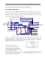
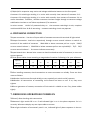
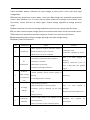
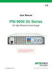
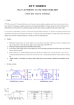
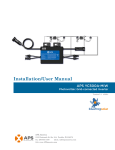
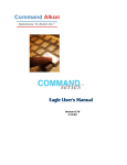
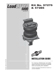
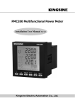
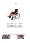
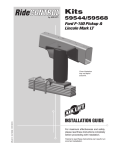
SBW Series
LARGE POWER FULLY-AUTOMATIC
COMPENSATION AC STABILIZER
USER’S MANUAL
1. INTRODUCTION..................................................................................................................... 2
2. MODEL AND SPECIFICATION............................................................................................ 2
3. SERVICE CONDITION........................................................................................................... 3
4. LEADING COMPONENTS..................................................................................................... 3
5. WORKING PRINCIPLE..........................................................................................................4
6. INSTALLING CONNECTION................................................................................................6
7. DEBUGGING OPERATIONG POWER ON......................................................................... 6
8.APPARENT SIZE.......................................................................................................................8
9. OPERATION MAINTENANCE..............................................................................................8
10. RANDOM FILE...................................................................................................................... 8
1
1. INTRODUCTION
The design of SBW series three-phase automatic segregated compensation electron voltage
regulator has introduced western advanced techniques and combined with national condition
to regularize AC voltage. When voltage fluctuates because of external power web voltage
undulation or load change, the series can automatically maintain stability of output voltage.
Compare with other style of Manos tats, the series feature large volume, high efficiency, no
waved distortion, stable voltage regulation, wide load availability, and manual/automatic shift.
The series can bear instant overload and can work continuously for long time and equipped
with over voltage protection, phase protection, phase-order protection and machine hitch
automatic protection function. Its advantage contains small volume, light weight, convenient
installment and use, reliable implementation, and so on.
The application of SBW includes
broadcast.telecommunication.medical.commercial.industrial.research.It
system.laboratory
marine.railways.aviation.utilities etc. It provides stable voltage power supply for telecom base
station.medical equipment elevator.numerical-controlled machine.printing machine.production
line etc.
2. Model and specification
1.MODEL AND MEANING
B
W
-
SERIES NO
STABILIZER RANGE
CAPACITY(KVA)
STABILIZER VOLTAGE
COMPENSATION
THREE PHASES
VOLTAGE STABILIZING RANGE:assure
output voltage of stabilizer only change within precision
range
INPUT VOLTAGE:305—456V
For Example: Capacity is 100KVA, Inuput voltage range from 305V to 456V, its model is
SBW-100KVA.
2
2.Mains technical parameter
a. Input voltage:380V±20%
b. Voltage stabilizing Precision:<3%;
c. Changing time:<1.5s;
Capacity(KVA
Output
Phase
)
voltage (V)
Current(A)
SBW-20
20
220
31
SBW-30
30
220
46
SBW-50
50
220
76
aneous :power cut ;
SBW-75
75
220
100
i. Endure instantaneous overload;
SBW-10
100
220
152
d.Output Phase Voltage:220V±3%;
Model
e. Frequency:50/60HZ;
f. Without additional distortion;
g. No phase shift ;
h.VoltageregulatedstablyNoinstant
j. Start-up power on (option)
0
k Over voltage(Phase voltage):250V±5V
l. under voltage(Phase voltage):183V±5V
Note: particular specifications have clients’ need made to order。
3. SERVICE CONDITION
Normal service condition of SBW series stabilizer in door is following:
1.Operating temperature: 0℃_40℃;
2.Comparative temperature:Rh90% 25℃;
3.Altitude:<1000 meter;
4.There is no strict gas,vapour, chemical sediment, dirt and other blasting and eroding medium
which affects stabilizer in the built-in location.
5.There is no strict libration and Jounce in the built-in location
6.User should negotiate with us when is not in accordance with above particular conditions.
4. LEADING COMPONENTS
1.Compensating transformer
When voltage magnitude and polarity of loop happen to change, it makes load loop bring
amplitude value and alterable polarity compensating voltage transformer.
2.Regulated transformer
Transtat TUV is a self regulation voltage three phase autotransformer and has three auto
symmetry slide brush.
Servo generator bring brush to slide along bareness parts of winding of
3
the self regulation voltage three phase autotransformer, stably regulate the second voltage to
reach to change compensated voltage and keep output voltage stable.
5. WORKING PRINCIPLE
1.SBW series three phases high-power segregated electric power stabilizer is made up of three
phase s compensated transformer TB, three phases transtat TUV, voltage detecting unit, servo
generator, transmission framework, contactor (breaker) manipulated circuit and protected
circuit,etc,its electrical principle chart as following:
DZ
CJ1
TBA
TBB
INPUT
输入
输出
OUTPUT
TBC
CJ2
CJ3
Serve
伺服系统
接触器操作电路
Contac
tor operation
system
电压检测
Sampling
TUV
保护电路
protect
Chart 1.SBW series three phase high-power segregated electric power stabilizer
2.Chart 2 is a voltage compensated principle ,It is made up of contacting booster TUV and
compensated transformer. Contacting booster connects output terminal of manostat and
compensated transformer is in series with main loop. Take A phase for instance,it describes
stable voltage’s working principle. Following chart 2 .
From Uao=Uai+ΔUac formular
Uai-manostat A phase input voltage;
Pic2 :Single phase sch
Uao-manostat A phase output voltage;
Uac-mansotat A phase compensated voltage
Its Working Principle as follows:
When A phase Input Voltage Uai increase Δ Uai, compensated voltage Uac correspond to
changeΔUac and ΔUac is equal to minus ΔUai make output voltage Uao hold the line,by
the same token B phase and C phase.
4
The process is stable voltage:
Based on variety of output voltage , Owing to voltage detecting unit sample, detecting and
output signal control servo generator M run and drive transtat TUV brush group slide and
modulate the second transtat to alter polarity and magnitude of compensated voltage, come
true output voltage level off automatically to reach automatical voltage stabilization
3.Three phase segregated manostat’s principle:
Three phase segregated manostat’s features are three phases adjusting independently, the
same with lopsided three phases input voltage, i.e. fluctuation of three phase input voltage is
lopsided through mansostat may gain stable three phases, balanceable output voltage.
3.1.Main Circuit: it is made up of three independent compensated transformers and six
transtats.
3.2.Each polarity and magnitude of compensated voltage of compensated transformer depends
on each input voltage .
voltage low
4.Control Loop
voltage high
A motor
Work normal
A phase
Control
board
Chart 3.Controlling board and circuit of contactor
4.A phase controlling board ( see chart 3 ) is made up of voltage detecting circuit and over
voltage protected circuit.
Output voltage modulation (phase voltage) depends on potentiometer VR1 to adjust.
Over voltage and under voltage depend on potentiometer VR2 to adjust.
KK is a button which sends power automatically. When it starts, there is no sending power
function, KK sends power automatically.
5
QT.QA1.QA2 is respective stop, mains and voltage stabilization buttons on the front panel.
Contactor CJ1 switchingin winding is in series with normally close contact of contactor CJ3 ,
Contactor CJ3 switchingin winding is in series with normally close contact of contactor CJ1 to
realize closedown. Therefore , whether manostat circulate straight through to converse voltage
stabilization circulate or not? Must stop button QT to converse.
In series contact
JA.JB.JC of protected relay on
the contactor switchingin circuit, complete
machine add DZ then JA.JB.JC attracting,contactor switching circuit may operate.
6. INSTALLING CONNECTION
1.Input connection:live wire of Input cable of manostat connect with terminal of light switch
2.Output Connection: Load wire respectively through current mutual inductor to switch on
terminal of the medial AC contactor
SBW-100K or above manostat pull on a cycle ( 200/5
current mutual inductor);SBW-50K or below manostat pull on two cycles100/5,75/5,50/5
current mutual inductor),Or current indicates uncorrectly.
3.Input Neutral wire:Neutral wire connect to hand insulated terminal of manostat, its crust can
connect ground.
4.Three phase cables chose according to magnitude of machine. Following is for your reference.
Capacity
(KVA)
Lead(mm2)
20
30
50
75
100
180
225
320
6
10
16
24
35
90
150
240
5.After installing manostat, check connections to assure manostat run reliably. There are three
notes as follows:
5.1.Whether lead connect fast and reliably or not, especially air switch and AC contacts.
5.2.Whether all connections of controlling circuit board are loose or not? If so, they must
tighten.
5.3.Servo generator of transtat, connection of limit switch is reliable or not. If so, please solder
tightly.
7. DEBUGGING OPERATIONG POWER ON
1.Electrify after checking with connections
2.Manostat’s light switch DZ is on. If red indicated light is on in the phase sequence. So it is
correctly. Whereas redeploy any two input cable to connect.
3.Here light indication of manostat’s panel is on, indicated light of phase sequence is also on.
6
Please pressQA1 button, indication of input voltage of front panel is the same with input
voltage table.
4.Please press stop button to shut down , then press QA2 plough into automatic compensated
system. Here indicator is on. If it can’t start up, phase sequence is wrong or lack of phase, then
shut down, correct and turn on switch again. Output voltage regulates to voltage precision
range
5.When manostat run under the voltage stabilization and start up, namely load shut down..
6.If you want to know output voltage, please circumvolve linear switch on the manostat’s panel.
7.KK button must pressed on the phase sequence, if there is an auto start-up function
8.Well Modulating before Output voltage adjusting and under voltage setting
9.Ordinary faults and solutions:
No
malfunction
Cause
1.Phase sequence of Input connection makes a
1
No Start-up
mistake or Electric power is deviant.
2.Brake doesn’t be off or is attaited
1.controlling connection board is attainted
2
No
stabilization
2.Generator is attainted
3.Mechanism system fault
4.Load feed back higher harmonic
Action of
3
Stable voltage
has a direction
only
Solution
1.Redeploy cable
2.off-brake or Replace air switch
Item
1.2.3 must repaired or
changed
Sampling transformer power of
item 4 adds filter and purified
signal.
1.Switch normally closed contacts plough or
attainted
Replacing
2.Controlling board is attainted.
1.Stop pressing QT button
4
No output
Voltage
2.Stable voltage QA2 contacting shatter
Item
1.2.3 must repaired or
3.Contactor CJ2,CJ3 shattered On the main changed
Loop
Whether Item 4 has faults or not.
4.Fault protection
5
Continuous
off-brake
1.Under voltage must be not adjusted on the
Controlling board
2.change resistance on the controlling board
7
Adjusted
professional
and
repaired
by
8.APPARENT SIZE
Appearances
Capacity (KVA)
Dimension
(k*w*h)mm
20
485*730*1135
30
485*730*1135
50
570*810*1430
75
1620*890*1560
100
1620*890*1560
Single Cabinet
9. OPERATION MAINTENANCE
According to different operational environment, maintenance cycle has biggish discrepancy, but
it is not more than 6 months. Normal maintenance is following:
1.Quite clearing all parts of stabilizer to not remain dust and dirt,especially nude brush and
contacting adjustor. Brush glide guide strip and shift gears must be cleared with gasoline and
woven fabric of cotton
2.Replace attrited brush;
When user find faults or destroyed components, it must be mended or replaced timely.
3.Maintenance recordation
10. RANDOM FILE
1.USER’S MANUAL
2.Products Warranty Card
8