1
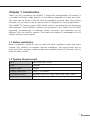
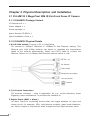
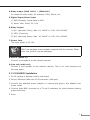
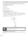
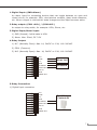
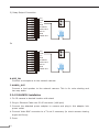
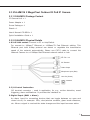
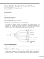
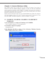
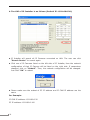
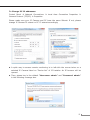
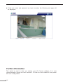
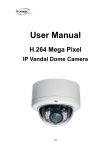
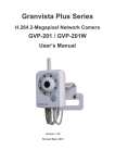
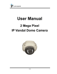
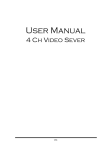
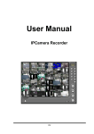
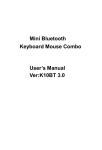
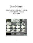
2 Mega-Pixel Indoor / Outdoor IR IP Camera ICA-HM132 / ICA-HM136 / ICA-HM316 / ICA-HM316W Quick Installation Guide Table of Contents Chapter 1. Introduction..................................................................................... 3 1.1 Before Installation................................................................................ 3 1.2 System Requirements........................................................................... 3 Chapter 2. Physical Description and Installation................................................... 4 2.1 ICA-HM132 2 Mega-Pixel 20M IR Vari-Focal Dome IP Camera.................. 4 2.1.1 ICA-HM132 Package Content......................................................... 4 2.1.2 ICA-HM132 Physical Details.......................................................... 4 2.1.3 ICA-HM132 Installation................................................................. 5 2.2 ICA-HM136 2 Mega-Pixel 20M IR Vandal Proof Dome IP Cam................... 6 2.2.1 ICA-HM136 Package Content......................................................... 6 2.2.2 ICA-HM136 Physical Details.......................................................... 6 2.2.3 ICA-HM136 I/O Control Instruction................................................ 6 2.2.4 ICA-HM136 Installation................................................................. 8 2.3 ICA-HM316 2 Mega-Pixel Outdoor IR PoE IP Camera............................... 9 2.3.1 ICA-HM316 Package Content......................................................... 9 2.3.2 ICA-HM316 Physical Details.......................................................... 9 2.3.3 ICA-HM316 Installation................................................................10 2.4 ICA-HM316W 2 Mega-Pixel 11n Outdoor IR IP Camera...........................11 2.4.1 ICA-HM316W Package Content.....................................................11 2.4.3 ICA-HM316W Installation.............................................................12 Chapter 3. Camera Windows Utility...................................................................13 3.1 ICA-HM132 / ICA-HM136 / ICA-HM316 / ICA-HM316W IP Assignment.....13 Further Information.........................................................................................16 Chapter 1. Introduction Thank you for purchasing the PLANET 2 Mega-Pixel Wire/Wireless IP-Camera. It is versatile and high image solution of surveillance application for day and night. The video can be stored in the SD card and playback remotely. With user friendly interface, it is an easy-to-use IP camera which is designed for security application. The PLANET IP Camera support Multi-Profile function can stands for simultaneously video streams. These Network Cameras can generate H.264, MPEG-4 and M-JPEG streaming simultaneously to different clients. Moreover, the resolution can be different from one client to another. This state-of-art design is considerable to fit in various network environments. 1.1 Before Installation Before installation, please be sure to read this quick installation guide and user’s manual (CD) carefully to complete machine installation. This guide shows how to quick set up the cameras, unless model name specified terms “IP Camera” will be used for these models. 1.2 System Requirements CPU Intel Dual Core 1.66G RAM 1024MB Graphic card 128MB Display Resolution 1024 x 768 24bits Operating System Windows 2000, XP, 2003, Vista 32bit, Win7 32bit Network Ethernet 10/100 Base-T 3 Chapter 2. Physical Description and Installation 2.1 ICA-HM132 2 Mega-Pixel 20M IR Vari-Focal Dome IP Camera 2.1.1 ICA-HM132 Package Content IP Camera Unit x 1 Power Adapter x 1 Screw package x 1 User’s Manual CD-ROM x 1 Quick Installation Guide x 1 2.1.2 ICA-HM132 Physical Details 1.RJ-45 LAN socket: Connect to PC or Hub/Switch. For connect to 10Base-T Ethernet or 100Base-TX Fast Ethernet cabling. This Ethernet port built N-Way protocol can detect or negotiate the transmission speed of the network automatically. Please use CAT-5 cable to connect the Network Camera to a 100Mbps Fast Ethernet network switch or hub. DC 12V / 1A I/O Terminal Video Output Microphone Input (Red) Line Out (Green) Network 2.I/O Control Instruction I/O terminal connector – used in application, for e.g., motion detection, event triggering, alarm notifications. It provides the interface to: 3.Digital Input (GND + Alarm) An alarm input for connecting devices that can toggle between an open and closed circuit, for example: PIRs, door/window contacts, glass break detectors, etc. When a signal is received the state changes and the input becomes active. 4 4.Relay output (COM +N.O.) / (COM+N.C.) An output to relay switch, for example: LEDs, Sirens, etc 5.Digital Input/Alarm Input 1) GND (Ground): Initial state is LOW 2) Alarm: Max. 50mA, DC 3.3V 6.Relay Output 1) N.C. (Normally Close): Max. 1A, 24VDC or 0.2A, 110~240VAC 2) COM: (Common) 3) N.O. (Normally Open): Max. 1A, 24VDC or 0.2A, 110~240VAC 7.Power Jack The input power is DC 12V. Note ONLY use package power adapter supplied with the internet. Otherwise, the product may be damaged. 8.MIC in (audio in) Connect a microphone to the network camera. 9.Line out (audio out) Connect a loud speaker to the network camera. This is for voice alerting and two-way audio. 2.1.3 ICA-HM132 Installation 1.Fix IR camera to desired location with stand 2.Plug-in Ethernet Cable into RJ-45 connector (LAN port) 3.Connect the attached power adapter to camera and plug-in this adapter into power outlet 4.Connect Video BNC connector to a TV set if necessary (to check camera viewing angle and focus) 5.Done 5 2.2 ICA-HM136 2 Mega-Pixel 20M IR Vandal Proof Dome IP Cam 2.2.1 ICA-HM136 Package Content Camera unit x 1 Power Adapter x 1 Accessories Kit x 1 User’s Manual CD-ROM x 1 Quick Installation Guide x 1 2.2.2 ICA-HM136 Physical Details 1.RJ-45 LAN socket: Connect to PC or Hub/Switch. For connect to 10Base-T Ethernet or 100Base-TX Fast Ethernet cabling. This Ethernet port built N-Way protocol can detect or negotiate the transmission speed of the network automatically. Please use CAT-5 cable to connect the Network Camera to a 100Mbps Fast Ethernet network switch or hub. 2.Power Jack: The input power is DC 12V. Power Jack Note RJ-45 ONLY use package power adapter supplied with the internet. Otherwise, the product may be damaged. 2.2.3 ICA-HM136 I/O Control Instruction I/O terminal connector – used in application, for e.g., motion detection, event triggering. 6 1.Digital Input: (GND+Alarm) An alarm input for connecting devices that can toggle between an open and closed circuit, for example: PIRs, door/window contacts, glass break detectors, etc. When a signal is received the state changes and the input becomes active. 2.Relay output: (COM +N.O.) / (COM+N.C.) An output to relay switch, for example: LEDs, Sirens, etc. 3.Digital Input/Alarm Input: 1) GND (Ground): Initial state is LOW 2) Alarm: Max. 50mA, DC 3.3V 4.Relay Output: 1) N.C. (Normally Close): Max. 1A, 24VDC or 0.2A, 110~240VAC 2) COM: (Common) 3) N.O. (Normally Open): Max. 1A, 24VDC or 0.2A, 110~240VAC 5.Relay Connection: 1) Digital Input connection N.O COM N.C GND ALARM IN N.O AUDIO OUT COM MIC IN N.C GND VIDEO OUT ALARM IN AUDIO OUT MIC IN GND VIDEO OUT N.O COM N.C GND ALARM IN N.O AUDIO OUT COM MIC IN N.C GND VIDEO OUT ALARM IN AUDIO OUT MIC IN GND VIDEO OUT N.O COM N.C GND ALARM IN N.O AUDIO OUT COM MIC IN N.C GND RELAY OUT ALARM IN RELAY OUT ALARM IN Door/Window Contacts IN Door/Window Contacts IN 7 AUDIO GND OUT MIC IN IN ALARM GND AUDIO OUT VIDEO MIC IN OUT 2) Relay Output Connection Contacts IN GND VIDEO OUT N.O COM N.C N.O GND COM ALARM IN N.C AUDIO OUT GND MIC IN IN ALARM GND AUDIO OUT VIDEO MIC IN OUT GND VIDEO OUT Or N.O COM N.C N.O GND COM ALARM IN N.C AUDIO GND OUT MIC IN IN ALARM GND AUDIO OUT VIDEO MIC IN OUT GND VIDEO OUT 6.MIC_IN: Connect a microphone to the network camera. 7.AUDIO_OUT Connect a loud speaker to the network camera. This is for voice alerting and two-way audio. 2.2.4 ICA-HM136 Installation 1.Fix IR camera to desired location with stand 2.Plug-in Ethernet Cable into RJ-45 connector (LAN port) 3.Connect the attached power adapter to camera and plug-in this adapter into power outlet 4.Connect Video BNC connector to a TV set if necessary (to check camera viewing angle and focus) 5.Done. 8 2.3 ICA-HM316 2 Mega-Pixel Outdoor IR PoE IP Camera 2.3.1 ICA-HM316 Package Content IP Camera Unit x 1 Power Adapter x 1 Screw Package x 1 Stand x 1 User’s Manual CD-ROM x 1 Quick Installation Guide x 1 2.3.2 ICA-HM316 Physical Details 1.RJ-45 LAN socket: Connect to PC or Hub/Switch. For connect to 10Base-T Ethernet or 100Base-TX Fast Ethernet cabling. This Ethernet port built N-Way protocol can detect or negotiate the transmission speed of the network automatically. Please use CAT-5 cable to connect the Network Camera to a 100Mbps Fast Ethernet network switch or hub. DC 12V / 1A I/O Terminal Video Output Microphone Input (Red) Line Out (Green) Network 2.I/O Control Instruction I/O terminal connector – used in application, for e.g., motion detection, event triggering, alarm notifications. It provides the interface to: 3.Digital Input (GND + Alarm) An alarm input for connecting devices that can toggle between an open and closed circuit, for example: PIRs, door/window contacts, glass break detectors, etc. When a signal is received the state changes and the input becomes active. 9 4.Relay output (COM +N.O.) / (COM+N.C.) An output to relay switch, for example: LEDs, Sirens, etc 5.Digital Input/Alarm Input 1) GND (Ground): Initial state is LOW 2) Alarm: Max. 50mA, DC 3.3V 6.Relay Output 1) N.C. (Normally Close): Max. 1A, 24VDC or 0.2A, 110~240VAC 2) COM: (Common) 3) N.O. (Normally Open): Max. 1A, 24VDC or 0.2A, 110~240VAC 7.Power Jack The input power is DC 12V. Note ONLY use package power adapter supplied with the internet. Otherwise, the product may be damaged. 8.MIC in (audio in) Connect a microphone to the network camera. 9.Line out (audio out) Connect a loud speaker to the network camera. This is for voice alerting and two-way audio. 2.3.3 ICA-HM316 Installation 1 .Fix IR camera to desired location with stand 2.Plug-in Ethernet Cable into RJ45 connector (LAN port) 3.Connect the attached power adapter to camera and plug-in this adapter into power outlet 4.Connect Video BNC connector to a TV set if necessary (to check camera viewing angle and focus) 5.Done 10 2.4 ICA-HM316W 2 Mega-Pixel 11n Outdoor IR IP Camera 2.4.1 ICA-HM316W Package Content IP Camera Unit x 1 Power Adapter x 1 Screw package x 1 Stand x 1 5dbi Antenna x 1 User’s Manual CD-ROM x 1 Quick Installation Guide x 1 2.4.2 ICA-HM316W Physical Details 1.RJ-45 LAN socket: Connect to PC or Hub/Switch. For connect to 10Base-T Ethernet or 100Base-TX Fast Ethernet cabling. This Ethernet port built N-Way protocol can detect or negotiate the transmission speed of the network automatically. Please use CAT-5 cable to connect the Network Camera to a 100Mbps Fast Ethernet network switch or hub. DC 12V / 1A I/O Terminal Video Output Microphone Input (Pink) Line Out (Green) Network 2.I/O Control Instruction I/O terminal connector – used in application, for e.g., motion detection, event triggering, alarm notifications. It provides the interface to: 3.Digital Input (GND + Alarm) An alarm input for connecting devices that can toggle between an open and closed circuit, for example: PIRs, door/window contacts, glass break detectors, etc. When a signal is received the state changes and the input becomes active. 11 4.Relay output (COM +N.O.) / (COM+N.C.) An output to relay switch, for example: LEDs, Sirens, etc 5.Digital Input/Alarm Input 1) GND (Ground): Initial state is LOW 2) Alarm: Max. 50mA, DC 3.3V 6.Relay Output 1) N.C. (Normally Close): Max. 1A, 24VDC or 0.2A, 110~240VAC 2) COM: (Common) 3) N.O. (Normally Open): Max. 1A, 24VDC or 0.2A, 110~240VAC 7.Power Jack The input power is DC 12V. Note ONLY use package power adapter supplied with the internet. Otherwise, the product may be damaged. 8.MIC in (audio in) Connect a microphone to the network camera. 9.Line out (audio out) Connect a loud speaker to the network camera. This is for voice alerting and two-way audio. 2.4.3 ICA-HM316W Installation 1.Fix IR camera to desired location with stand 2.Plug-in Ethernet Cable into RJ45 connector (LAN port) 3.Connect the attached power adapter to camera and plug-in this adapter into power outlet 4.Connect Video BNC connector to a TV set if necessary (to check camera viewing angle and focus) 5.Done 12 Chapter 3. Camera Windows Utility This chapter shows how to quick set up your H.264 IP Camera. The H.264 IP Camera is with the default settings. However to help you find the networked camera quickly the windows utility (PLANET IP Installer) can search the cameras in the network that shall help you to configure some basic setting before you started advanced management and monitoring. Please insert the bundle CD disk into your CD/DVD-ROM drive. When the welcome web page appears, please click your IP camera name on the IP camera list. Then click the PLANET IPInstaller hyperlink to start the PLANET IP Installer. 3.1 ICA-HM132 / ICA-HM136 / ICA-HM316 / ICA-HM316W IP Assignment 1.Use “IP Installer” to assign an IP address of IP CAMERA. The IP Installer software is in the attached CD. 2.IP Installer supports languages. IPInstallerEng.exe 3.OS: Windows XP SP2 or above. If the following “Windows Security Alert” popup, please click “Unblock”. 13 4.The GUI of IP Installer is as follows (Default IP: 192.168.0.20). IP Installer will search all IP Cameras connected on LAN. The user can click “Search Device” to search again. Click one of IP Cameras listed on the left side of IP Installer, then the network configuration of that IP Camera will be listed on the right side. If parameters changed, click on “Submit”. Then, the network configuration will be changed. Just click “OK” to reboot Please make sure the subnet of PC IP address and IP CAM IP address are the same. For Example: IP CAM IP address: 192.168.0.20 PC IP address: 192.168.0.100 14 To Change PC IP addresses: Control Panel Network Connections Local Area Connection Properties Internet Protocol (TCP/IP) Properties Please make sure your IP Camera and PC have the same Subnet. If not, please change IP Camera IP subnet or PC IP subnet accordingly. A quick way to access remote monitoring is to left-click the mouse twice on a selected IP Camera listed on “Device list” of IP Installer. An IE browser will be opened. Then, please key in the default “Username: admin” and “Password: admin” in the following message box. 15 If the user name and password are input correctly, the following web page will be displayed. Further Information This guide is used to help you startup your IP Camera settings. It is also recommended to check the user manual in CD disk for more details of the system and user configuration. 16