1
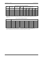
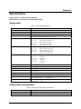
Chapter 5 Specifications Typical for 25 °C unless otherwise specified. Specifications in italic text are guaranteed by design. Analog input Table 1. Analog input specifications Parameter Specification Number of channels Input range Gain Calibration 32 differential (2 banks of 16) ±10 V Switch selectable by bank, additive values of X1, X10, X100, X200 and X500 Two offset potentiometers per bank (16 channels) and one Cold Junction Compensation adjustment potentiometer per board. Gain = 1 0.002% typical, 0.02% max Gain = 10 0.005% typical, 0.05% max Gain = 100 0.01% typical, 0.1% max Gain = 200 0.02% typical, 0.2% max Gain = 500 0.05% typical, 0.5% max Gain = 1 0.0005% typical, 0.005% Gain = 10 0.001% typical, 0.01% max Gain = 100 0.002% typical, 0.01% max Gain = 200 0.003% typical, 0.01% max Gain = 500 0.005% typical, 0.02% max Gain = 1 ± 20 ppm / °C Gain = 10 ± 20 ppm / °C Gain = 100 ± 40 ppm / °C Gain = 200 ± 60 ppm / °C Gain = 500 ± 100 ppm / °C Offset ± 15 µV / °C ±10 V 90 dB 7 Hz, selectable through solder bridge (C pad) -50 mV at positive input when thermocouple is open, selectable through solder bridge (V pad) 100k ohms to ground, selectable through solder bridge (G pad) V and G pads open: 2 nA typical, 6 nA max V and G pads open: >100 Meg Ohms min V and G pads shorted 100 k Ohms min Power on: ±35 V Power off: ±20 V Gain error Non-linearity Temperature coefficient Common mode range CMRR @ 60 Hz Input filter Open thermocouple detect Input ground reference Input leakage current Input impedance Absolute maximum input voltage Cold junction compensation Table 2. Cold junction compensation specifications Parameter Specification CJC output voltage CJC zero crossing 24 mV / °C 0 mV at 0 °C 23