1
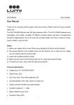
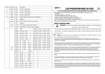
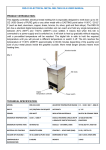
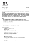
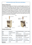
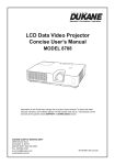
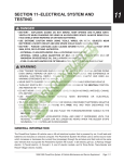
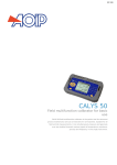
DIGITAL PANEL METER
GLOBAL
BUYERS
STORE
Instruction
YOUR BEST ONLINE STORE
Manual
G
G lob
G lob al
G lob al Bu
G lob al Bu ye
G lob al Bu ye rs
G lob al Bu ye rs St
G lob al Bu ye rs St ore
G lob al Bu ye rs St ore
G lob al Bu ye rs St ore
G lob al Bu ye rs St ore
G lob al Bu ye rs St ore
lo a B y rs S or
ba l B uy er S to e
l B uy er s S to re
uy er s S to re
er s S to re
s to re
St r
or e
e
Thank you for purchasing our product !
One-Year Limited Warranty
Globalbuyersstore warrants your newly purchased product against defects in
material and workmanship existing at the time of manufacture for a period of one years from the date of purchase.
Warranty Registration is not necessary to obtain the applicable warranty on the product. The date of purchase will
be used to determine the warranty period when warranty service is requested.
It is important to read the Setup Guide before installing or commissioning this instrument
as it contains important information relating to safety and EMC.
Please verify the panel cutout dimensions and mount according to instructions.
SAFETY CONSIDERATIONS
Unpacking and Inspection
Your instrument has been carefully tested and inspected prior to shipment. Unpack
the instrument and inspect for obvious shipping damage. Please do not attempt to
install or operate the unit if damage is found.
This instrument is a panel mount device protected in accordance with Class I of EN
61010. Installation of this instrument should be done by Qualified personnel. In order
to ensure safe operation, the following instructions should be followed.
This instrument has no power-on switch; it will be in operation as soon as power is connected.
Do not make signal wiring changes or connections when power is applied to the instrument.
Make signal connections before power is applied and, if reconnection is required, disconnect
the power before such wiring is attempted. Do not connect more than one meter to the same
power supply if the meters cannot use the same signal ground.
Do not exceed voltage rating stated on the specifications.
Always disconnect power before changing signal and power connections.
Do not use this instrument on a work bench without its case for safety reasons.
Do not operate this instrument in flammable or explosive atmospheres.
Do not expose this instrument to rain or moisture.
Whenever EMC is an issue, always use shielded cables.
Instrument which will not be installed immediately should be stored in a clean, dry location.
WARNING:
The use of this instrument in a manner other than specified may impair the
protection of the instrument and subject the user to hazard.
Careful use of the instrument will provide years of reliable service.
Please consult your licensed electrician/electrical engineer for professional advice before installation.
At the end of its life cycle, dispose of this product in accordance with local and national disposal regulations.
The information contained in this document is believed to be correct but we accept no liability for any errors
it may contain, and reserve the right to alter specifications without notice.
Copyright © 2006-2012 Globalbuyersstore Digital World. All Rights Reserved.
This document may not be copied,photocopied, reproduced, translated, or reduced to any electronic
medium or machine-readable form, inwhole or in part, without our prior written permission.
Copyright © 2006-2012 www.globalbuyersstore.com
e-mail : [email protected]
P. 1/6
GLOBALBUYERSSTORE - 1/16 DIN PID Digital Temperature Controller
INSTRUCTION MANUAL
G
G lob
G lob al
G lob al Bu
G lob al Bu ye
G lob al Bu ye rs
G lob al Bu ye rs St
G lob al Bu ye rs St ore
G lob al Bu ye rs St ore
G lob al Bu ye rs St ore
G lob al Bu ye rs St ore
G lob al Bu ye rs St ore
lo a B y rs S or
ba l B uy er S to e
l B uy er s S to re
uy er s S to re
er s S to re
s to re
St r
or e
e
Version 3 .2
3. Front Panel and Operation
Caution
This controller is intended to control equipment under normal operating
conditions. If failure or malfunction of it could lead to an abnormal operating
condition that could cause personal injury or damage to the equipment or
other property, other devices (limit or safety controls) or systems (alarm or
supervisory) intended to warn of or protect against failure or malfunction of
the controller must be incorporated into and maintained as part of the
control system.
⑥
①
⑦
⑤ ④ ③ ②
1. Features
Figure 1. Front panel
The PID control with artificial intelligent enhancement for precision
temperature control.
Auto-tuning function can find the best PID parameter automatically.
On/off control mode for refrigerator, motor and solenoid valve control
application.
Bumpless transfer between Auto and Manual control.
Limit control for safety protection and special applications.
The output can be set for SSR output control or relay contactor control by
the user.
Two contact relays can be configured as one PID and one alarm output,
dual alarm outputs, or dual On/off control.
Support 10 different types of commonly used temperature sensor inputs.
① AL1 Relay J1 output indicator
AL2 Relay J2 output indicator
AT- On for manual mode. Blinking during auto-tuning process
OUT- SSR output indicator
② Value increment/Select next parameter
③ Value decrement/Select previous parameter
④ Auto tuning/Digit shift
⑤ Set/Confirm/Manual Auto switching/Reset (for Limit control mode)
⑥ Measured temperature, or, Process Value (PV)
⑦ Set temperature, or, Set Value (SV)
4. Terminal Wiring (back view)
+
SSR
-
TC
RTD + -
W
2. Specification
6
Thermocouple (TC): K, E, S, R, J, T, B, WRe3/25
RTD(Resistance temperature detector): Pt100, Cu50
Input type
Input range
See table 2
Display
Dual lines, four digits, °F or °C
Display resolution
1°C, 1°F; or 0.1°C, 0.1°F with Pt100
Accuracy
±0.2% or ±1 unit of full input range
Control mode
PID, On-off. Limit, Manual
Output mode
Relay contact: 3A at 250VAC, SSR: 8VDC, 30 mA.
Alarm
Process high/low alarm
Power consumption
<2 Watt
Power supply
85-265V DC or 85-265V AC/50~60Hz
Sample rate
4 samples/sec
Operating condition
0 ~ 50 °C, ≤85% RH
Mounting cutout
45 x 45 mm
Dimension
48x48x75mm (1/16 DIN)
7
9
11
13
12
14
2
1
+
8
R
3
R
10
4
J2
NO
5
-
com NO
J1
COM = Common, always connect to this, it is the moving part of the relay's switch.
NC = Normally Closed, COM is connected to this when the relay coil is off.
NO = Normally Open, COM is connected to this when the relay coil is on.
Power
NC
85-265V
Figure 2. Wiring diagram
4.1 Sensor connection
4.1.1 Thermocouple
The thermocouple should be connected to terminals 9 and 10. Make sure that
polarity is correct. There are two commonly used color codes for the K type
thermocouple. US color code uses yellow (positive) and red (negative).
Imported DIN color code uses red (positive) and green/blue (negative). The
temperature reading will decrease as temperature increases if the connection
is reversed.
Copyright © 2006-2012 www.globalbuyersstore.com
e-mail : [email protected]
P. 2/6
GLOBALBUYERSSTORE
Parameter Display
Operation Mode
SET
Enter Code
SET
SET
XXXX
Input Sensor Selection
SET
XXXX
inty
0089
SET
Output mode selection
SET
X
outy
G
G lob
G lob al
G lob al Bu
G lob al Bu ye
G lob al Bu ye rs
G lob al Bu ye rs St
G lob al Bu ye rs St ore
G lob al Bu ye rs St ore
G lob al Bu ye rs St ore
G lob al Bu ye rs St ore
G lob al Bu ye rs St ore
lo a B y rs S or
ba l B uy er S to e
l B uy er s S to re
uy er s S to re
er s S to re
s to re
St r
or e
e
4.1.2 RTD sensor
For a three-wire RTD with standard DIN color code, the two red wires should be
connected to the terminals 9 and 10. The white wire should be connected to
terminal 8.
For a two-wire RTD, the wires should be connected to terminals 8 and 9. Jump
a wire between terminals 9 and 10.
Set controller input type, Inty, to P100 (1° resolution) or P10.0 (0.1° resolution).
4.2 Power to the controller
The DC power cables should be connected to terminals 1 and 2. Terminal
1 is positive and 2 is negative. When connecting to an AC power source,
polarity does not matter. It can be powered by 85 - 265V AC/DC power source.
Neither a transformer nor jumper is needed to wire it up. For the sake of
consistency with the wiring example described later, we suggest you connect the
hot wire to terminal 2 and neutral to 1. Since the controller is in a plastic shell,
ground wire is unnecessary.
5.1 System Configuration Parameters (accessed by code 0089)
The system configuration parameter s are listed in table 1. To change the
parameters, press SET , enter code “0089” and press SET again. Then, follow
the flow chart in Figure 3.
4.3 Control output connection
Two control output options are offered by this controller. (1) The SSR control
output provides an 8V DC signal that can control up to 4 SSRs in parallel. (2)
The J2 relay output can be used to turn on a contactor or a solenoid valve. It
can also drive a small heater directly if the heater draws <3 Amperes. For
application that needs two control outputs, such as one for heating and other for
cooling, J1 relay can be used for the second output with on/off control mode.
Please note J1 can’t be used for main control output. Both J1 and J2 can be
used as alarm output if they are not used as control output.
4.3.1 Connecting the load through SSR (Solid State Relay)
Connect the terminal 7 to the negative input and terminal 6 to the positive input
of the SSR. Set the system output configuration, outy, to 2 or 3 - depending on
the control mode used. See Application Example for details.
4.3.2 Connecting the load through the built-in relay
J1 relay is for alarm output only. Set the system output configuration, outy, to
0,1,2,3, or 4 - depending on the control mode used. Please see Application
example for details.
4.4 For first time users without prior experience with PID controllers, the
following notes may prevent you from making common mistakes:
4.4.1 The power to the heater does not flow through terminal 1 and 2 of the
controller. The controller consumes less than 2 watts of power. It only
provides a control signal to the relay. Therefore, 20 gauge wires are sufficient
for providing power to terminal 1 and 2. Thicker wires may be more difficult to
install.
4.4.2 The J1, J2 relay are “dry single pole switches”. They do not provide
power by themselves. Figure 09 shows how it is wired when providing a 120V
output (or when output has the same voltage as the power for controller). If
the load of relay requires a different voltage than that for the controller, an
additional power source will be needed (Please see Application
Example.)
.
4.4.3 SSR output power does not come from the input of the SSR. The output
of the SSR is a single pole switch between terminal 1 and 2 of the SSR. The
input of the SSR is for control, or triggering, the SSR. (Please note we are
talking about the SSR itself, not the SSR control output of the controller).
Figure 10 shows how the SSR output should be wired. When switching a
North American 240V AC power, the heater will be live even when the SSR is
off. User should install a double-pole mechanical switch to the power input.
4.4.4 SSR (Solid State Relay) has infinite life time if it is used properly.
It will make the controller last longer.
5. Parameter Setting
For safety reasons, the controller parameters are divided into three groups
with different pass codes. You should only give the code to those who have
the responsibility and knowledge of how to properly change it. Code 0089
contains the parameters for system configuration that may need to change
during the initial set up. Code 0036 contains the parameters for tuning
performance. Code 0001 is for controlling temperature and alarm settings.
Hysteresis Band
SET
Input offset
SET
psb
SET
SET
XXXX
Heating/Cooling
SET
SET
X
rd
Display Unit(C/F)
corf
SET
SET
XXXX
HY
X
SET
end
Figure 3. System setup flow chart
(1) Press
to enter setting mode;
(2) Press > , and
to enter parameters;
(3) Press SET to confirm;
(4) Press
or
to select the new parameter.
SET
Table 1. System configuration parameters
Description
Setting Range
Initial
Note
Inty
Inty
Input Sensor Type
See table2
P10.0
1
outy
outy
Control Output Mode
0,1,2,3,4
2
2
Hy
Hy
Hysteresis Band
0~9999
0.3
3
PSb
PSb
Input Offset
rd
rd
Control Function
CorF
CorF
Display Unit
End
End
Exit
Code
-1000~1000(deg)
0: heating 1: Cooling
0: °C 1:°F
0.0
0
0
Note 1. The controller is preset for RTD type of sensor input. If any other type
of sensor is used, the Inty value needs to be changed to the corresponding
symbol as shown in Table 2.
Table 2. Temperature sensor code
Sy mbol
t
r
j
WRE
b
s
k
e
P10. 0
P100
Cu50
t
r
J
WRE
b
s
k
e
P10.0
P100
Cu50
Description
TC, Ty pe T
TC, Ty pe R
TC, Ty pe J
TC, WRe3/25
TC, Ty pe B
TC, Ty pe S
TC, Ty pe K
TC, Ty pe E
RTD, Pt100
RTD, Pt100
RTD, Cu50
Working Temperature Range
-200~400 °C; -320~752 °F
-50~1600 °C; -58~2900 °F
-200~1200 °C; -320~2200 °F
0~2300 °C; 32~4200 °F
350~1800 °C; 660~3300 °F
-50~1600 °C; -58~2900 °F
-200~1300 °C; -320~2400 °F
-200~900 °C; -320~1650 °F
-199.9~600.0 °C; -326.2~1112.0 °F
-199~600 °C; -326~1112 °F
-50.0~150.0 °C; -60~300 °F
Note 2. The value of outy determines the control mode. When it is set to:
0 - Relay J1, J2 as alarm output; SSR output disabled; SV value invalid;
1 - Relay J1 as alarm output; J2 as PID controlled relay contact output; SSR
output disabled; AH2 and AL2 setting invalid; used in maintaining a
constant temperature (SV=Target temperature);
2 - Relay J1, J2 as alarm output; SSR PID non-contact control output; used in
maintaining a constant temperature (SV=Target temperature);
3 - Relay J1, J2 as alarm output; SSR for Limit control output;SV=Control Value;
4 - Relay J1 as alarm output; J2 as Limit control relay contactor output; SV=
Control value; SSR output disabled; AH2 and AL2 setting invalid.
Copyright © 2006-2012 www.globalbuyersstore.com
e-mail : [email protected]
P. 3/6
GLOBALBUYERSSTORE
G
G lob
G lob al
G lob al Bu
G lob al Bu ye
G lob al Bu ye rs
G lob al Bu ye rs St
G lob al Bu ye rs St ore
G lob al Bu ye rs St ore
G lob al Bu ye rs St ore
G lob al Bu ye rs St ore
G lob al Bu ye rs St ore
lo a B y rs S or
ba l B uy er S to e
l B uy er s S to re
uy er s S to re
er s S to re
s to re
St r
or e
e
Note 3. Hysteresis Band (also called dead band, or differential), Hy, is used for
On/off control and Limit control. Its unit is in degrees (° C or °F). For On/off
control mode, the output will be off when PV>SV and on again when PV <SVHy for heating. For cooling, the output will be off when PV<SV and on again
when PV>SV+Hy. For Limit control mode, the controller can not be reset (to
turn on the output) when PV>SV-Hy for heating, and when PV< SV+Hy f o r
cooling.
Note 9. Cycle rate (ot): It is the time period (in seconds) that the controller use
to calculate its output. e.g. If ot=2, and the controller output is set to 10%, the
heater will be on 0.2 second and off 1.8 seconds for every 2 seconds. Smaller
ot value result in more precision control. For SSR output, ot is normally set at
2. For relay or contactor output, it should be set longer to prevent contacts
from wearing out too soon. It normally set to 20~40 seconds.
Note 1 0 . Digital Filter (FILt): FILt=0, filter disabled; FILt=1, weak filtering
effect; FILt=3, strongest filtering effect. Stronger filtering increases the stability
of the readout display, but causes more delay in the response to changes in
temperature.
5.2 PID Parameters (accessed by code 0036)
The PID and relevant parameters are listed in table 3. To change the
parameters, press SET , enter code “0036”, and press SET again. The
parameter flow chart is similar to Figure 3.
Table 3. PID and relevant parameters
Sy mbol
P
I
d
SouF
ot
FILt
End
P
I
d
SouF
ot
FILt
End
Description
Setting Range
Initial
Note
Proportional Constant
Integral Time
Deriv ativ e Time
Damp Constant
Cy cle Rate
Digital Filter Strength
Ex it
0.1~99.9(%)
2~1999(Sec)
0~399(Sec)
0.1~1.0
2~199(Sec)
0~3
5.0
100
20
0.2
2
0
5
6
7
8
9
10
The values of the P, I, and D parameters are critical for good response time,
accuracy and stability of the system. Using the Auto-tune function to
automatically determine these parameters is recommended for the first time
user. If the auto-tuning result is not satisfactory, you can manually fine-tune
the PID constants for improved performance.
Note 5. Proportional Constant (P): P is also called the proportional band. Its
unit is the percentage of the temperature range. e. g. For a K type
thermocouple, the control range is 1500 °C. P=5 means the proportional
band is 75 °C (1500x5%). Assuming the set temperature (SV) = 200. When
integral, I, and derivative, d, actions are removed, the controller output power
will change from 100% to 0% when temperature increases from 125 to
200°C. The smaller the P value is, the stronger action will be for the same
temperature difference between SV and PV.
Note 6. Integral time (I): Brings the system up to the set value by adding to
the output that is proportional to how far the process value (PV) is from the
set value (SV) and how long it has been there. When I decreases, the
response speed is faster but the system is less stable. When I increases,
the respond speed is slower, but the system is more stable.
Note 7. Derivative time (d): Responds to the rate of PV change, so that the
controller can compensate in advance before |SV-PV| gets too big. A larger
number increases its action. Setting d-value too small or too large would
decrease system stability, causing oscillation or even non-convergence.
Normally, d is set to 1/4 of the I value.
Note 8. Damp constant: This constant can help the PID controller further
improve the control quality. It uses artificial intelligence to dampen the
temperature overshoot. When its value is too low, the system may
overshoot. When its value is too high, the system might be over damped.
SouF too low
SouF acceptable
Figure 4. Damp constant
SouF too high
5.3 Temperature setting and Alarm setting (accessed by code 0001)
The temperature and alarm parameters are listed in table 4. To change the
parameters, press SET , enter code “0001” an d press SET again. The
parameter flow chart is similar to Figure 3.
Table 4. Temperature and alarm parameters
Description
Initial Setting
Note
Target temperature(Set Value)
J1 on temperature
J1 off temperature
J2 on temperature
J2 off temperature
Ex it
80.0
80.0
90.0
80.0
90.0
11
12
Sy mbol
SV
AH1
AL1
AH2
AL2
END
SV
AH1
AL1
AH2
AL2
END
Note 11. There are two ways to set the target temperature.
a. During the normal operation mode, press
or
once to switch the
display from PV to set value. The display will start to blink. Press
or
again to increase or decrease the SV. When finished, wait 8 seconds and the
settings will take effect automatically (the display will stop blinking).
b. Press SET key once. Use > ,
and
keys to enter code 0001. Press
SET key to confirm, then the display would be SV (Su). Press SET key again
to display the SV setting. Use > , and
keys to enter the new SV value
and press SET to confirm. Press
key to change the display to END. Then,
press SET to exit. You can also ignore the steps after confirmation of SV. The
controller will returns to normal operation mode automatically if no key is
pressed for 1 minute.
Note 12. Alarm setting. The J1 relay is controlled by parameters AH1 and
AL1. And the J2 relay is controlled by parameter AH2 and AL2. AH1 (or AL2)
is the temperature to turn the J1 (or J2) relay on; AL1 (or AL2) is the
temperature to turn the J1 (or J2) relay off. When AH1>AL1 (or AH2>AL2), the
J1 (or J2) alarm is set for absolute high alarm as shown in Figure 5 below.
When AH1 <AL1 (or AH2<AL2) , the J1 (or J2) alarm is set for absolute low
alarm as shown in Figure 6 below. When AH1=AL1 (or AH2=AL2), the J1 (or
J2) alarm is deactivated.
Please note that J2 can’t be used as alarm when Outy is set to 1 or 4.
PV
AH1
AL1
SV
PV
AL1
AH1
SV
Relay on
Figure 5. Absolute high alarm
Relay on
Figure 6. Absolute low alarm
6. Auto-Tuning
The auto-tuning function (also called self tuning) can automatically optimize
the PID parameters for the system. The auto-tuning function will use the On/
off mode to heat up the system until it passes the set point. Then let it cool
down. It will repeat this about three times. Based on the response time of the
Copyright © 2006-2012 www.globalbuyersstore.com
e-mail : [email protected]
P. 4/6
GLOBALBUYERSSTORE
system, the built-in artificial intelligence program will calculate and set the PID
parameters for the controller. If your system has a very slow response, the
auto-tuning could take a long time.
AT calculation
AT end
K-type TC
G
G lob
G lob al
G lob al Bu
G lob al Bu ye
G lob al Bu ye rs
G lob al Bu ye rs St
G lob al Bu ye rs St ore
G lob al Bu ye rs St ore
G lob al Bu ye rs St ore
G lob al Bu ye rs St ore
G lob al Bu ye rs St ore
lo a B y rs S or
ba l B uy er S to e
l B uy er s S to re
uy er s S to re
er s S to re
s to re
St r
or e
e
AT start
9. Application Example
9.1 A furnace needs to be controlled at 1200 °F. The power source is 120V
AC. The heating element is 1800W/120V. It is switched on/off by a contactor.
The coil voltage of the contactor is 120V AC. A K type thermocouple is used
as the temperature sensor.
a. Wiring diagram (The Load can be powered by a separate supply source.)
-
+
ON OFF ON
ON/OFF
6
OFF
PID
12
Figure 7. Auto-tuning
1
6.1 To activate Auto-tuning, press and hold > key until the “AT” indicator
starts to blink, which indicates auto-tuning is in progress. When “AT” stops
blinking, the auto-tuning is finished. Now, newly calculated PID parameters
are set to be used for the system. Please note that Auto-tuning is only for PID
control mode (when “outy” is set at 1 or 2).
6.2 To stop the Auto-tuning, press and hold > key until “AT” indicator
stops blinking. Then, the previous PID parameters value are resumed.
9
13
8
7
11
10
14
2
4
3
5
Heater
N
120VAC
L
Fuse
Contactor
Figure 9. Typical wiring for high power and high temperature applications
such as oven or kiln temperature control
7. Manual mode
Manual mode allows the user to control the output as a percentage of the total
heater power. It is like a stove dial. The output is independent of the
temperature sensor reading. One application example is controlling the
strength of boiling during beer brewing. You can use the manual mode to
control the boiling so that it will not boil over to make a mess. The manual
mode can be switched from PID mode but not from On/off mode. To switch
from the PID to the manual mode, press and hold the SET key until the
“ AT ” indicator turned on (about 4 seconds). In the manual mode, the top
display is for the process temperature. The bottom right is the percentage of
power output. The bottom left display show an “M” for user to easily identify
the controller is in manual mode. To switch from manual to PID mode,
press and hold SET key until the “ AT ” indicator turned off. This controller
offers “bumpless” switch from the PID to manual mode. If the controller
outputs 75% of power at PID mode, the controller will stay at 75% when it is
switched to the manual mode, until it is adjusted manually.
8. Limit control mode.
b. Parameter setting. These are the parameters that need to be changed from
the initial value: outy=1 for PID mode with relay output; ot=20 to increase the
relay life time; SV=1200°F for the target temperature.
9.2 A water tank needs to be controlled at 200.0°F. If temperature is over
205.5 °F, the alarm will turn on to warn the operator and turn off when the
temperature drops below 205.3 °F. The system consists of a 1200W 120V AC
heater, a Pt100 RTD sensor, a 25A AC SSR, and a 12 V DC buzzer.
SSR (Solid State Relay) has infinite life time if it is used properly. It will
make the controller last longer.
a. Wiring diagram (The Load can be powered by a separate supply source.)
Wiring the controller or heater with 240V AC is the same as with 120V AC
Heater
N
120VAC L
The Limit control mode will shut the heater off when SV is reached. The
heater will not be turned on again until the controller is reset manually (press
the SET key for 5 seconds). When powered on, it will not start the heating
until reset button is pressed. The controller can’t be reset when the
temperature is within Hysteresis Band (Hy).
To use the Limit control mode, set outy to 3 or 4. Then, set the Hy to the
range that you want reset to be blocked. To start the heating or cooling,
press SET key for 5 second or until the out indicator is on.
Fuse
+ -1
SSR
4
3
+ -
RTD
2
6
7
11
W
R
R
8
9
13
10
12
1
2
14
3
4
Buzzer
12VDC
SV
PV
5
PV
100
97
SV
SV-Hy
Start
outy=4, SV=100, Hy=3. The
heating stops after it reached 100
degree.
Relay on
Figure 8. Limit control mode
Figure 10. Typical wiring for high precision control set up. It shows how the
RTD sensor and SSR should be wired.
b. Parameter setting. These are the parameters that need to be changed
from the initial value: Inty=P10.0 for Pt100 RTD sensor with 0.1° resolution
input, SV=200.0 °F for the target temperature. AH1=205.5 °F and AL1=
205.3 °F for the alarm.
Copyright © 2006-2012 www.globalbuyersstore.com
e-mail : [email protected]
P. 5/6
GLOBALBUYERSSTORE
9.3 A furnace needs to be controlled to hold a temperature. Power source
is 240V AC. Heating element is 1800W/240V. It is switched by a contactor.
The coil voltage of the contactor is 24V AC. A K-type thermocouple is used
as the temperature sensor.
11.1 Display EEEE
This is an input error message. The possible reasons are, the sensor is not
connected correctly; the input setting is wrong type; or the sensor is defective.
If this happens when using thermocouple sensor, you can short terminals 9
and 10. If the display shows the ambient temperature, the thermocouple is
defective. If it still displays EEEE, check the input setting, Inty, to make sure it
is set to the right thermocouple type. If Inty setting is correct, the controller is
defective. For RTD sensor, check the input setting first because most
controllers are shipped with input set for thermocouple. Then check the wiring.
The two red wires should be on terminals 9 and 10. The clear wire should be
on terminal 8.
G
G lob
G lob al
G lob al Bu
G lob al Bu ye
G lob al Bu ye rs
G lob al Bu ye rs St
G lob al Bu ye rs St ore
G lob al Bu ye rs St ore
G lob al Bu ye rs St ore
G lob al Bu ye rs St ore
G lob al Bu ye rs St ore
lo a B y rs S or
ba l B uy er S to e
l B uy er s S to re
uy er s S to re
er s S to re
s to re
St r
or e
e
K-type TC
11. Error Message and trouble shooting
+ -
6
7
11
8
12
2
1
9
13
10
J2
14
3
4
5
24VAC
L2
240VAC L1
Fuse
Contactor
Heater
Figure 11. Wiring example for a load that requires different voltages than
that for the controller power supply. This diagram also applies to a 24V
solenoid valve if the contactor and heater are replaced by the valve.
9.4 Drive a load directly
K-type TC
+ -
6
7
11
8
12
1
L
10
J2
14
3
4
11.3 Poor Accuracy
Please make sure calibration is done by immersing the probe in liquid.
Comparing with reference in air is not recommended because response time
of sensor depends on its mass. Some of our sensor has response time >10
minutes in the air. When the error is larger than 5°F, the most common
problem is improper connection between the thermocouple and the controller.
The thermocouple needs to be connected directly to the controller unless a
thermocouple connector or an extension wire is used. A copper connector,
copper wire, or thermocouple extension wire with wrong polarity connected on
the thermocouple will cause the reading drift more than 5°F.
5
Small Heater
N
120VAC
2
9
13
11.2 No heating
When controller output is set for relay output, the “AL2” LED is synchronized
with output relay. When controller output is set for SSR output, the “OUT” LED
is synchronized with SSR control output. If there is no heat when it is
supposed to, check the AL2 or OUT first. If it is not lit, the controller parameter
setting is wrong. If i t is on, check external switching device (if the relay is
pulled-in, or the red LED of the SSR). If the external switching device is on,
then the problem is either the external switching device output, its wiring, or
the heater. If the external switching device is not on, then the problem is either
the controller output, or the external switch device.
Fuse
Figure 12. This is for loads that draw less than 3 Amp of current only. For
parameter settings, please refer to “example (1)”.
Copyright © 2006-2012 www.globalbuyersstore.com
e-mail : [email protected]
P. 6/6