1
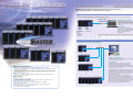
PC-Based Data Acquisition Unit
A PC-based data acquisition system for the future, delivering
unparalleled performance. When combined with Yokogawa's proprietary
PC software, the MX100's high speed, multi channel capability, and high
withstand voltage offers the ultimate in measurement power.
www.yokogawa.com/tm/
... and subscribe to “Newswave,”
our free e-mail newsletter
Bulletin 04M08B01-00E
MX100 is a data acquisition unit designed to operate as a front end for PCs.
Data measured by MX100 is transferred to PCs in real-time.
Connection between a single MX unit and a single PC (measurement of 24 channels/10 ms or 60 channels/100 ms)
One MX unit enables data acquisition on up to 24 channels at a measurement interval of 10 ms or up to 60 channels at a
measurement interval of 100 ms (six modules installed in both cases).
Measured data
<Setting up the System>
The MX and PC are connected via a
hub and a straight Ethernet cable.
Alternatively, they can be connected
using a cross cable alone, without
using the hub.
HUB
Straight cable
100Base-TX
<PC Software>
Input signal:
DC voltage
Thermocouple
RTD
Digital input
(Mixed input
possible)
In a one-to-one connection, the
MX100 standard software included
with the main module facilitates easy
building of data acquisition
environments.
Output signal:
Digital output
One MX unit consists of a combination of a main module, input/output modules, and a
base plate. This configuration centers on the main module. For details, refer to pages
4 and 5.
Connection between multiple MX units and a single PC (for measurement of up to 1,200 channels and the use of MXLOGGER)
Example of a system with multiple MX units:
HUB
Straight cable
100Base-TX
<Setting up the System>
The MX units and the PC are connected by means of a
hub and straight Ethernet cables.
<PC Software>
Acquisition of data from multiple MX units is wellsupported by Yokogawa’s software “MXLOGGER”
(optional). MXLOGGER enables data acquisitions of up
to 20 MX units (one unit has inputs of up to 60 channels,
or 1,200 channels on 20 units).
Maximum Performance.....
■ High-Speed, Multi-Channel Capability, High withstand Voltage
• Shortest measurement interval of 10 ms (high-speed measurement of 10 ms on 24 channels or 100
ms on 60 channels is possible).
• Possible to acquire data from up to 1,200 channels (when using Yokogawa's proprietary software).
• Reinforced insulation between the input terminal and the case handles 3700 Vrms for one minute, or
600 Vrms/VDC continuous.
■ Multi-Interval Measurement
• Mixed use of three types of measurement intervals is enabled within the system (measurement
intervals are set for each module).
Please note that the shortest measurement interval of
MXLOGGER depends on the system's total number of
channels and the PC's performance. For guidelines on
measurement intervals and the number of channels,
please refer to page 6.
•
•
•
If users wish to create their own data acquisition
software, there is no limit to the number of MX units that
can be integrated with a single PC software element.
Please note, however, that if conditions with heavy loads
(such as short measurement intervals with many units)
are set to the PC and its software, data will not be
acquired in time and some data may be lost.
Ease of Use.....
■ Flexible System Configuration
By configuring modules, a system can be built or modified to utilize 4 to 1,200 channels, and
measurement intervals of 10 ms to 60 s.
■ Versatile PC-Based Software Options
Software developed by Yokogawa, an API, and a LabVIEW driver are available.
■ Easy Software Setup
PC software developed by Yokogawa automatically identifies any connected MX100s.
Up to 20 units
■ No Re-Wiring between Measurements
A removable terminal unit is available.
2
3
The MX is designed to enable desired
measurement environments by combining three
elements: the main module, input/output
modules, and a base plate.
The assembled unit can be utilized on the
desktop as-is (the modules have legs). Please
note that DIN rails are used for rack-mounting.
Base Plate
Input/Output Module
Main Module
Main Module (MX100)
The main module is the engine that controls data acquisition. It is equipped with a power supply, an
Ethernet port, and a CompactFlash card slot. One main module can accommodate up to six input/output
modules. The user can choose up to six moduels of any type.
Ethernet Port:
For communication with the PC.
Automatic recognition of 100Base-TX
or 10Base-T
Data Backup Time by CF Card Size
(Note: Minutes/hours/days are approximate.)
Number of
saved channels
10 channels
CF (CompactFlash) Card Slot:
With the CF Card, measured data is
saved to the card if communication
with the PC is interrupted. Since the
card provides data backup, you do not
have to worry about the possible loss
of data even if the MX is configured for
PC-based measurement.
24 channels
60 channels
Measurement
interval
32 M
128 M
512 M
10 ms
100 ms
500 ms
2s
10 ms
100 ms
500 ms
2s
10 ms
100 ms
500 ms
2s
2 hours
21 hours
4.5 days
18 days
54 minutes
9 hours
45 hours
7.5 days
18 minutes
3.5 hours
18 hours
3 days
9 hours
3.5 days
18.5 days
75.5 days
3.5 hours
37 hours
7.5 days
31.5 days
75 minutes
15 hours
3 days
12.5 days
36 hours
15 days
75.5 days
303 days
15 hours
6 days
31.5 days
126 days
5 hours
2.5 days
12.5 days
50 days
Input/Output Modules (MX110, MX115, MX125)
■ Four-Channel High-Speed Universal Input Module
MX110-UNV-H04
Note: All I/O
modules are fitted
with a swing-up
terminal cover.
MX110-UNV-M10
Shortest measurement interval: 10 ms;
Maximum number of input channels: 4
channels;
Mixed input of DC voltage,
thermocouple, RTD, and digital input:
possible.
Please note that the shortest
measurement interval for temperature
is 50 ms for this module.
Shortest measurement interval: 100 ms;
Maximum number of input channels:
10 channels;
Mixed input of DC voltage,
thermocouple, RTD, and digital input:
possible
■ Ten-Channel High-Speed Digital Input Module
■ Ten-Channel Medium-Speed Digital Output Module
MX115-D05-H10
If a single unit consists of this
module only, measurement of 60
channels/10 ms is possible.
Most suitable for measurement of
digital input signals at many points
inexpensively.
Shortest measurement interval: 10 ms;
Maximum number of input channels:
10 channels;
Digital input dedicated module.
4
■ Ten-Channel Medium-Speed Universal Input Module
MX125-MKC-M10
For use of alarm outputs, etc.
Shortest output interval: 100 ms;
Maximum number of output channels:
10 channels;
Digital output dedicated module.
Base Plate (MX150)
The main module and input/output modules are connected by means of connectors on a base plate.
For one input/output module
through
Although the position for the main module is fixed, input/output
modules can be configured in any position using the module
connectors. One to six modules can be used.
○ ○ ○
six input/output modules
<Using the Base Plate for Six Input/Output Modules>
Connector covers (772066) are available for vacant slots.
Modules and Terminals
<Attachable/Detachable Terminals>
All input terminals can be attached/detached. If the user provides multiple terminals, there is no need to perform rewiring every
time measurement is carried out.
■ Four-Channel High-Speed
■ Ten-Channel Medium-Speed Universal ■ Ten-Channel Medium-Speed
Universal Input Module
Input Module
Digital Output Module
MX110-UNV-H04
MX110-UNV-M10
MX125-MKC-M10
■ Ten-Channel High-Speed Digital Input
Module
MX115-D05-H10
Plate with clamp
terminals (with
RJC)(772063)
MX115-D05-H10’s plate
with clamp terminals
does not have RJC.
RJC: Reference
Junction Compensation
Clamp terminal
(772064)
Each terminal can be attached/detached.
Clamp terminal
(772065)
Each plate with terminals can be attached/detached.
Each terminal can be attached/detached.
<Screw Terminal Block>
A separate screw terminal block is available for the MX110-UNV-M10 Ten-Channel Medium-Speed Universal Input Module and
the MX115-D05-H10 Ten-Channel High-Speed Digital Input Module.
Connection Cable (772062) between input
modules and the screw terminal block
Detach the plate with clamp terminals from the MX110-UNVM10 or MX115-D05-H10. Then, use the connection cable
(772062) to connect the input module without the plate to the
screw terminal block (772061).
Screw Terminal Block (772061)
The screw terminal block is installed.
The option code /NC can be added to the MX110-UNV-M10
and MX115-D05-H10 to indicate whether or not the plate with
clamp terminals is included at the time of delivery. If the user
requires only the screw terminal block and not the clamp
terminals, please specify either MX110-UNV-M10/NC or
MX115-D05-H10/NC.
<Mounting of Racks or Panels Using the DIN Rail>
Use the DIN rail for mounting on racks or panels. The DIN rail
can be easily attached using the dedicated bracket. Two
brackets come standard with the base plate (MX150).
Bracket for mounting the
DIN rail
5
High-Speed, Multi-Channel Capability
The table below provides reference information on the maximum number of measurable channels in relevant measurement
intervals (when using Yokogawa's proprietary software):
PC Software
Measurement
interval
Maximum
number of
measurable
channels
10 ms
24 channels
50 ms
24 channels
50 ms
120 channels
100 ms
Number of Necessary Modules (example)
MX100
Standard
Software
MXLOGGER
Main Module
(MX100)
DCV/DI
√
√
1
6
-
DCV/TC/RTD/DI
√
√
1
6
-
DCV/TC/RTD/DI
-
√
5
30
-
60 channels
DCV/TC/RTD/DI
√
√
1
0
6
100 ms
300 channels
DCV/TC/RTD/DI
-
√
5
0
30
200 ms
500 channels
DCV/TC/RTD/DI
-
√
9
0
50
500 ms
600 channels
DCV/TC/RTD/DI
-
√
10
0
60
1000 ms
1200 channels
DCV/TC/RTD/DI
-
√
20
0
120
Measurable objects
Four-Channel High-Speed Ten-Channel Medium-Speed
Universal Input Module
Universal Input Module
(MX110-UNV-H04)
(MX110-UNV-M10)
√ measurement that support is possible
- measurement that support is not possible.
The relationship between measurement intervals and the number of channels largely depends on the performance of the PC.
The actual performance may differ from that shown in the table.
<PC System Requirements> CPU: Pentium 4 3.2 GHz; Memory: 1 GB; OS: Windows 2000; Hard disk: 160 GB;
Communication interface: Ethernet 100Base-TX
Multi-Interval Measurement
Three types of measurement intervals can be used in a single system in various combinations. Measurement intervals are
specified for each module. It is also possible to set different types of input modules to the same measurement interval or to set
the same type of input modules to different measurement intervals. Twelve measurement intervals are available as userselectable options: 10 ms, 50 ms, 100 ms, 200 ms, 500 ms, 1 s, 2 s, 5 s, 10 s, 20 s, 30 s and 60 s. Please note, however, that
measurement intervals of 10/50 ms cannot be set to the Medium-speed Universal Input Module (MX110-UNV-M10).
<Examples of Setting Measurement Intervals>
<Monitor Window Using Yokogawa's Proprietary PC Software>
Multi-interval systems can be flexibly built for
each module as shown in the figure below.
Three colors
are used to indicate the three
types of measurement intervals.
The window shows measurement values by measurement intervals.
Measurement can be performed while confirming rapidly-changing signals
and slowly-changing signals simultaneously.
Example 1
Example 2
Example 3
Measurement of sine
waves at 8 Hz with a
measurement interval of
10 ms
Measurement of sine
waves at 0.5 Hz with a
measurement interval of
100 ms
6
Measurement of
sine waves at 1
Hz with a
measurement
interval of 50 ms
High Withstand Voltage (Reinforced Insulation)
Reinforced (double) insulation has been provided between the input terminals and the case to achieve a high withstand voltage
of 600 Vrms/VDC (continuous). As shown below, each battery voltage can be measured even if the batteries are stacked to
increase common-mode voltages.
Allowable common-mode
voltage of one MX system:
Vmax = 600 Vrms/Vdc (continuous)
MX system
Measurement object
CHn
CH (n–1)
•
*
•
Module (N)
•
CH1
Allowable common-mode
voltage between modules
Vmax = 600 Vrms/Vdc (continuous)
CHn
•
*
•
Module 1
•
CH2
CH1
N: 4 or 10
* Allowable common-mode voltage between channels in a module
• Ten-Channel Universal Input Module: 120 Vrms/Vdc (continuous)
• Four-Channel Universal Input Module: 250 Vrms/Vdc (continuous)
Noise Rejection (MX110-UNV-H04)
MX input modules employ integrating A/D converters with superior noise rejection performance. In particular, the MX110-UNVH04 Four-Channel High-Speed Universal Input Module incorporates an integrating A/D converter for each input channel, thereby
exhibiting strong noise rejection performance in high-speed measurement. Moreover, the digital filtering function is effective on
noises that cannot be fully rejected even with integrating A/D converters. Time constants can be selected from 5 to 100
measurement interval times. Therefore, filtering can be applied according to the noise to be rejected.
<Example of Noise Rejection>
When the noise source in the left figure was applied to the MX, the result in the right figure was obtained. High-speed
measurement can be stably performed even in noise environments.
• Output window of MX100 for noise inputs
Module used: MX110-UNV-H04 Four-Channel High-Speed Universal
Input Module
Measurement with the range of 2 V (-2 V to +2 V), measurement
interval of 50 ms, integral time “Auto” and filter “OFF.”
• Noise source applied to MX
The noise signal was applied
between H and L (in normal mode).
1V
1V
200 ms
–1 V
–1 V
10 µs
Sampling rate: 500 MS/s
Measurement using Yokogawa’s Digital Oscilloscope
DL1740.
The MX Standard Software was used for PC software.
7
MX100 Standard Software (Standard Software for the Main Module MX100)
This software is used to connect a single MX unit for performing data acquisition (it is not possible to connect multiple MX units).
It includes three software elements: integration monitor, viewer, and calibration.
<Integration Monitor Software>
This software performs real-time monitoring and logging of measured data. It consists of six menus: Monitor Window, Detailed
Display Setting, Channel Setting, Acquisition Condition, System Setting, and Connection/disconnection.
• Monitor Window
• Acquisition Condition
This window is used to monitor measured data in real-time. It
enables waveform displays and digital displays.
This menu is used to set various conditions (such as
measurement intervals/data save intervals, measurement start/
end conditions, or file name designation) for data acquisitions.
Drag and drop the
symbol of the input
module. Then, allocate it
to the measurement
interval group.
Digital output signals can be
generated manually from
these buttons.
Integration Monitor Software provides
menu bars in all windows. The user can
make transitions to other menu
windows from any menu window.
• Detailed Display Setting
• System Setting
This menu is used to set data display states (such as waveform
colors) in the monitor window.
This menu is used to decide module configurations, etc. Module
configurations are shown in easily understood diagrams.
• Channel Setting
• Connection/Disconnection (Easy to Set Up)
This menu is used to enter individual settings (such as range
settings) for each input channel or to set computation channels
(such as the input of computing equations).
The connected MX100 is identified automatically. Once
connection setting information is provided, it will be retained.
When the system restarts, the MX100 will be connected
automatically without making network settings.
The connected
MX100 is
identified
automatically.
MX being used by other users can
be confirmed here.
Select the MX to be connected. If necessary, provide network settings such as IP
addresses. All of the network settings/changes can be performed from the PC
software: there is no need to access the MX100 itself directly (for example,
hardware switch settings).
8
<Viewer Software>
<Calibration Software>
This software is intended to re-display saved data. It enables
waveform displays, digital displays, cursor displays, interval
arithmetic, and other functions.
This software is intended to efficiently carry out the calibration
of universal input modules.
Measured data can be converted
into various formats such as Excel,
Lotus, or ASCII.
Data saved in multiple measurement
intervals are re-displayed in each
measurement interval (using one data
file).
Results of interval arithmetic
MXLOGGER (Optional PC Software)
MXLOGGER is used to connect multiple MX units (up to 20 units) for data acquisition (one MX unit can also be connected). It
consists of software elements (setting, logger (for saving data), monitor, and viewer) and the monitor server.
The monitor server function is used to enable connections with Yokogawa’s data logging software, “DAQLOGGER.” It is effective
when combining MX units with Yokogawa’s data acquisition equipment such as DARWIN and DAQSTATION. (DAQLOGGER is
scheduled to be capable of supporting MXLOGGER’s monitor server function in July 2003.)
Example of building a mixed system of MX100 and DARWIN:
DAQLOGGER becomes a client of MXLOGGER to simultaneously retrieve data from
MXLOGGER and from DARWIN.
DA100/DC100
Note: The shortest data acquisition interval of DAQLOGGER is one second. If it is necessary to save data with a measurement
interval of less than one second, data needs to be saved by MXLOGGER.
DR130/230/240
MV100/200
DAQLOGGER and MXLOGGER are provided
as basic software for Yokogawa’s data
acquisition PC software “DAQWORX.”
DX100/200
API for MX100/DARWIN (Optional)
If users wish to create their own data acquisition software, please use this API. The API consists of a suite of functions to
communicate with MX100/DARWIN. The suite of functions contains DLL (dynamic link library). API makes it possible to create
data acquisition software dedicated to the MX, or data acquisition software combining the MX and DARWIN, or data acquisition
software dedicated to DARWIN.
Three languages (Visual C, Visual C++, and Visual Basic) are supported.
9
Hardware Specifications
* Measurement Ranges and Accuracies
Common Specifications
Type
Input
• Normal operating conditions:
*
*
*
*
*
*
0-50˚C
20-80% RH for 0-40˚C
10-50% RH for 40-50˚C
Rated power supply voltage:
AC power supply, 100-240 VAC
Range of operating power supply voltage: AC power supply, 90-250 VAC
Power supply frequency:
50 Hz ± 2%, 60 Hz ± 2%
Power consumption: Up to approximately 70 VA when six modules are used
Installation method: Desktop/floor and panel mount (using the DIN rail)
Supported standards:
CSA
Obtained CSA22.2 No.1010.1,
20 mV
60 mV
200 mV
2V
6V
20 V
100 V
R
S
* Operating temperature range:
* Operating humidity range:
UL
CE
C-Tick
Voltage
Installation category (Overvoltage category): II, Degree of pollution: 2
Obtained UL61010B-1 (CSA NRTL/C)
EMC directive
EN61326
EN61000-3-2
EN61000-3-3
EN55011 Class A Group 1
Low voltage
EN61010-1
directive
Measurement category: II, Degree of pollution: 2
AS/NZS 2064 Class A Group 1
Thermocouple
RJC accuracy
not included.
Burn-out setting
is "OFF."
Model-Specific Specifications
• Main Module (MX100)
* Main functions:
Control of the power supply and input/output modules,
communication with the PC, storage of data on the CF card
(during a communication failure)
* Number of maximum connectable input/output modules:
6 (arbitrary for six modules or less)
* Measurement interval:
Up to three types can be set per system (multi-interval)
Types of measurement intervals are 10/50/100/200/500 ms, 1/2/
5/10/20/30/60 sec.
Note that configurable measurement intervals differ depending
on modules.
* Transfer interval of measured data to the PC: Minimum 100 ms
* DO interval (update interval):
100 ms (not synchronized with timing every measurement
interval of 100 ms)
* Filter function:
First-order lag filter. The function can be set for each channel.
Time constant = measurement interval × N (where N is any
number of the following: 5, 10, 20, 25, 40, 50, and 100).
* Input computation function (computation function that can be executed in the main module)
Computation of differences between channels:
differential computation between arbitrary channels (DCV, TC,
RTD, DI, scaling)
Linear scaling computation
Possible range for scaling:
DCV, TC, RTD, DI
Possible scope for scaling:
–30,000 to 30,000
Position of the decimal point: any digit
* Alarm (alarm function can be executed in the main module. This function is enabled even during a
communication failure).
Alarm types:
Upper limit, lower limit, differential upper limit, and differential
lower limit
Number of settings:
two items per channel
Possible range for alarm setting: DCV, TC, RTD, DI, scaling
Hysteresis:
Alarm “ON/OFF” values are set arbitrarily.
Number of alarm output points: 10-60 points according to the number of mounted “DO” modules
Output mode:
Excitation/non-excitation, OR, Hold/non-Hold, command output
* Saving the data
Save function:
Backup in the event of a communication failure during data
acquisitions by the PC.
Supported external media:
CF Card (up to 2 Gbytes) Type, I, II × one slot
Save trigger:
When the timeout value (60 s) is exceeded if communication is
interrupted during the PC’s data acquisitions.
Save channel:
Monitor “ON” channel
Save interval:
Data is saved automatically (approximately every 60 s)
Stopping the save function:
If the PC’s data acquisition is recovered or if the CF Switch is
pressed.
Data guarantee during a power failure:
Guaranteed until data is written immediately before the MX is
turned off (for example, power failure). The backup operation will
not continue after the system recovers from a power failure.
* Indication
LED:
Indication of Ethernet status.
7-segment indication:
MX status indication by 7 segments in 2 digits (unit no., operation
status indication, indication of error occurrence, indication of
messages concerning the CF Card, etc.)
* Communication functions
Interface:
100Base-TX/10Base-T (automatic detection) Ethernet
Basic protocol:
TCP, IP, UDP, ARP, ICMP
Transmission function:
Transmission of measured values and setting values
Receiving function:
Reception of setting values
* General specifications
Power consumption:
Approximately 8W for the main module only
Insulation resistance:
20 MΩ or more (500 VDC) between the power supply terminal
and the ground terminal
Withstand voltage:
1500 VAC (50/60 Hz) between the power supply terminal and the
ground terminal, one minute
External dimension:
Approximately 92 × 131 × 137 mm
Weight:
Approximately 0.85 kg
* Other functions
Switch:
8-bit dip switch (for IP address initialization, etc.)
CF switch:
Switch to stop the data writing operations.
RTD
measurement
current (1 mA)
RTD
measurement
current (2 mA)
DI
* Types of measurement:
10
Number of measurement points:
Input method:
A/D resolution:
Measurement interval:
A/D integral time:
DC voltage, thermocouple, RTD, DI (non-voltage contact, level (5
V logic))
4 (A/D to be equipped independently for each channel)
Floating unbalanced input, insulation between channels
±20000/±6000 (16-bit A/D is used)
10/50/100/200/500 ms, 1/2/5/10/20/30/60 s
1.67/16.67/20/36.67/100/200 ms, AUTO
A/D integral time is determined by measurement intervals
±(0.05% of rdg.⫹5 digits)
±(0.05% of rdg.⫹2 digits)
±(0.05% of rdg.⫹5 digits)
±(0.05% of rdg.⫹2 digits)
±(0.05% of rdg. ⫹1˚C)
However, R, S:
0 to 100˚C: ±3.7˚C
100 to 300˚C: ±1.5˚C
B: 400 to 600˚C: ±2˚C
B
0.0 to 1820.0˚C
Less than 400˚C: accuracy
is not guaranteed
±(0.05% of rdg. ⫹0.7˚C)
K
–200.0 to 1370.0˚C However, –200 to –100˚C:
±(0.05% of rdg. +1˚C) Measurement not possible
E
–200.0 to 800.0˚C
±(0.05%
of rdg. ⫹0.5˚C)
J
–200.0 to 1100.0˚C
However, J, L:
T
–200.0 to 400.0˚C –200 to –100˚C: ±(0.05%
of rdg. ⫹0.7˚C)
L
–200.0 to 900.0˚C
U
–200.0 to 400.0˚C
±(0.05% of rdg.⫹0.7˚C)
N
0.0 to 1300.0˚C
±(0.05% of rdg.⫹1˚C)
W
0.0 to 2315.0˚C
±(0.05% of rdg.⫹0.7K)
KpvsAu7Fe
0.0 to 300.0K
Pt100
–200.0 to 600.0˚C
±(0.05% of rdg. ⫹0.3˚C) Measurement not possible
JPt100
–200.0 to 550.0˚C
Pt100: high resolution –140.00 to 150.00˚C
±(0.05% of rdg. ⫹0.3˚C) Measurement not possible
JPt100: high resolution –140.00 to 150.00˚C
Ni100SAMA
–200.0 to 250.0˚C
±(0.05% of rdg. ⫹0.3˚C) Measurement not possible
Ni100 DIN
–60.0 to 180.0˚C
Ni120
–70.0 to 200.0˚C
Pt100
–200.0 to 250.0˚C
±(0.05% of rdg. ⫹0.3˚C) Measurement not possible
JPt100
–200.0 to 250.0˚C
Pt100: high resolution –140.00 to 150.00˚C
±(0.05% of rdg. ⫹0.3˚C) Measurement not possible
JPt100: high resolution –140.00 to 150.00˚C
Pt50
–200.0 to 550.0˚C ±(0.05% of rdg. ⫹0.3˚C)
Cu10 GE
–200.0 to 300.0˚C
Cu10 L&N
–200.0 to 300.0˚C
Measurement not possible
±(0.1% of rdg. ⫹0.7˚C)
Cu10 WEED
–200.0 to 300.0˚C
Cu10 BAILEY
–200.0 to 300.0˚C
±(0.05% of rdg. ⫹0.3K) Measurement not possible
J263B
0.0 to 300.0 K
Level
Vth = 2.4 V
Threshold level accuracy ±0.1 V
Contact
100 Ω or less: ON, 10 kΩ or more: OFF
0.0 to 1760.0˚C
Input
Type
Rated measurement
range
Measurement accuracy
integral time 16.67 ms or more
Measurement accuracy
integral time 1.67 ms
Voltage
60 mV
1V
6V
0 to ⫹60 mV
–1 V to ⫹1 V
0 to ⫹6 V
±(0.05% of rdg.⫹20 digits)
±(0.05% of rdg.⫹2 digits)
±(0.05% of rdg.⫹20 digits)
±(0.1% of rdg.⫹100 digits)
±(0.1% of rdg.⫹10 digits)
±(0.1% of rdg.⫹100 digits)
Supported thermocouple:
Supported RTD:
*
*
*
*
*
*
*
*
*
*
*
*
*
• Four-Channel High-Speed Universal Input Module (MX110-UNV-H04)
*
*
*
*
*
–20 mV to ⫹20 mV
–60 mV to ⫹60 mV
–200 mV to ⫹200 mV
–2 V to ⫹2 V
–6 V to ⫹6 V
–20 V to ⫹20 V
–100 V to ⫹100 V
Maximum
resolution
(1 digit)
±(0.1% of rdg.⫹25 digits) 1 µV
10 µV
10 µV
±(0.1% of rdg.⫹10 digits) 100 µV
1 mV
1 mV
10 mV
Measurement accuracy
integral time 1.67 ms
0.1˚C
0.1K
0.1˚C
0.01˚C
0.1˚C
0.1˚C
0.01˚C
0.1˚C
0.1K
* Special Input Ranges (that can be used in MXLOGGER)
• Base Plate (MX150)
* Number of main modules that can be equipped: 1 (always equipped)
* Number of I/O modules that can be equipped:
1-6 (to be specified according to the suffix codes)
Rated
Measurement accuracy
measurement range integral time 16.67 ms or more
*
*
*
*
*
*
*
Maximum
resolution
(1 digit)
1 µV
100 µV
100 µV
PLATINEL, PR40-20, NiNiMo, WRe3-25, W/WRe26, N (AWG14)
PT100 (high noise resistance), JPt (high noise resistance), Cu10
(at 20˚C, a = 0.00392), Cu10 (at 20˚C, a = 0.00393), Cu25 (at
0˚C, a = 0.00425), Cu53 (at 0˚C, a = 0.00426035), Cu100 (at
0˚C, a = 0.00425), Pt25, Cu10 GE (high resolution), Cu10 L&N
(high resolution), Cu10 WEED (high resolution), Cu10 BAILEY
(high resolution)
Reference junction compensation:
External/internal switchover can be performed for each channel.
Reference junction compensation accuracy:
During the measurement of 0˚C or more and during the input
terminal temperature balance
Type R, S, W: ±1˚C
Type K, J, E, T, N, L, U: ±0.5˚C
(Note) Internal reference junction compensation of Type B is fixed
to 0˚C.
Maximum input voltage:
200 mV DC range or less, thermocouple, RTD, DI (non-voltage
contact): ±10 VDC (continuous)
Other measurement ranges:
±120 VDC (continuous)
Normal-mode voltage:
DCV, TC, DI (level):
1.2 times of rated range or less (50/60 Hz, peak values including
signals)
RTD 100 Ω system:
50 mV peak
RTD 10, 25, 50 Ω systems:
10 mV peak
Normal-mode rejection ratio (NMRR):
When the integral time is 16.67 ms or more: 40 dB or more (50/60 Hz ±0.1%)
When the integral time is 1.67 ms: 50/60 Hz is not rejected.
Common-mode voltage:
600 VACrms (50/60 Hz), reinforced (double) insulation
Common-mode rejection ratio (CMRR):
120 dB or more when the integral time is 16.67 ms or more.
80 dB or more when the integral time is 1.67 ms (50/60 Hz
±0.1%, 500 Ω imbalance, between the minus measurement
terminal and the ground).
Common mode voltage between channels: 250 VACrms (50/60 Hz), double insulation
Noise rejection:
Rejection by the integrating A/D converter and the use of low
pass filters
Input resistance:
10 MΩ or more for the DC voltage of 200 mV range or less and
also for the thermocouple range. Approximately 1 MΩ if the DC
voltage is 2 V range or more. Approximately 1 MΩ while
measurement is stopped.
Insulation resistance:
20 MΩ or more between the input and the ground (500 VDC)
Input bias current:
10 nA or less (except for the burn-out setting)
Withstand voltage:
2300 VAC (50/60 Hz) between input terminals, one minute
3700 VAC (50/60 Hz) between an input terminal and the ground,
one minute
Input signal source resistance: 2 kΩ or less for DC voltage and thermocouple
10 Ω or less per cable for RTD 50 Ω or 100 Ω systems
1 Ω or less per cable for RTD 10 Ω or 25 Ω systems
Thermocouple burn-out:
Superposed electric current system, detection within the
thermocouple range (“ON/OFF” possible)
Parallel capacity during RTD:
0.01 µF or less
Power consumption:
Approximately 3 W
External dimension:
Approximately 57 × 131 × 150 mm (including the terminal cover)
Weight:
Approximately 0.5 kg
Terminal type:
Clamp terminal. Applicable cable size is 0.2-2.5 mm2 (AWG2412)
Approximately 57 × 131 × 150 mm (including the terminal cover)
Approximately 0.5 kg
Clamp terminal. Applicable cable size: 0.14-1.5 mm2 (AWG26-16)
* Types of measurement:
* External dimension:
* Weight:
* Terminal type:
*
*
• Ten-Channel High-Speed Digital Input Module (MX115-D05-H10)
• Ten-Channel Medium-Speed Universal Input Module (MX110-UNV-M10)
*
*
*
*
DC voltage, thermocouple, RTD (non-voltage contact, level (5 V
logic))
Number of measurement points: 10 (scanning of 10 channels with one A/D)
Input method:
Floating unbalanced input, insulation between channels (Note
that RTD is common among “b” terminals.)
A/D resolution:
±20000/±6000 (16-bit A/D is used)
Measurement interval:
100/200/500 ms, 1/2/5/10/20/30/60 s
A/D integral time:
1.67/16.67/20/36.67/100/200 ms, AUTO,
A/D integral time is determined by measurement intervals.
Measurement Ranges and Accuracies
Input
Type
20 mV
60 mV
200 mV
2V
6V
20 V
100 V
R
S
Voltage
Rated
Measurement accuracy
measurement range integral time 16.67 ms or more
–20 mV to ⫹20 mV
–60 mV to ⫹60 mV
–200 mV to ⫹200 mV
–2 V to ⫹2 V
–6 V to ⫹6 V
–20 V to ⫹20 V
–100 V to ⫹100 V
±(0.05% of rdg.⫹5 digits)
±(0.05% of rdg.⫹2 digits)
±(0.05% of rdg.⫹5 digits)
±(0.05% of rdg.⫹2 digits)
±(0.05% of rdg. ⫹1˚C)
However, R, S:
0 to 100˚C: ±3.7˚C
100 to 300˚C: ±1.5˚C
B:
400
to 600˚C: ±2˚C
0.0 to 1820.0˚C
B
Less than 400˚C: accuracy is not
guaranteed
±(0.05% of rdg. ⫹0.7˚C)
–200.0 to 1370.0˚C However, –200 to –100˚C:
K
Thermocouple
±(0.05% of rdg. ⫹1˚C)
RJC accuracy
–200.0 to 800.0˚C
E
±(0.05% of rdg. ⫹0.5˚C)
not included.
–200.0 to 1100.0˚C
J
However, J, L:
–200.0 to 400.0˚C
T
–200 to –100˚C:
–200.0 to 900.0˚C
L
±(0.05% of rdg. ⫹0.7˚C)
–200.0 to 400.0˚C
U
0.0 to 1300.0˚C
N
±(0.05% of rdg.⫹0.7˚C)
0.0 to 2315.0˚C
W
±(0.05% of rdg.⫹1˚C)
0.0 to 300.0K
KpvsAu7Fe
±(0.05% of rdg.⫹0.7K)
–200.0 to 600.0˚C
Pt100
±(0.05% of rdg. ⫹0.3˚C)
–200.0 to 550.0˚C
JPt100
Pt100: high resolution –140.00 to 150.00˚C
±(0.05% of rdg. ⫹0.3˚C)
JPt100: high resolution –140.00 to 150.00˚C
RTD
Ni100SAMA
–200.0 to 250.0˚C
measurement
Ni100 DIN
–60.0 to 180.0˚C
current (1 mA)
±(0.05% of rdg. ⫹0.3˚C)
Ni120
–70.0 to 200.0˚C
DI
Pt50
Cu10 GE
Cu10 L&N
Cu10 WEED
Cu10 BAILEY
J263B
Level
Contact
0.0 to 1760.0˚C
Maximum
resolution
(1 digit)
±(0.1% of rdg.⫹25 digits) 1 µV
10 µV
10 µV
±(0.1% of rdg.⫹10 digits) 100 µV
1 mV
1 mV
10 mV
±(0.1% of rdg. ⫹4˚C)
However, R, S:
0 to 100˚C: ±10˚C
100 to 300˚C: ±5˚C
B: 400 to 600˚C: ±7˚C
Less than 400˚C: accuracy is
not guaranteed
±(0.1% of rdg. ⫹3.5˚C)
However, –200 to –100˚C:
0.1˚C
±(0.1% of rdg. ⫹6˚C)
Measurement accuracy
integral time 1.67 ms
±(0.1% of rdg. ⫹2.5˚C)
However:
–200 to –100˚C:
±(0.1% of rdg. ⫹5˚C)
0.1K
±(0.1% of rdg. ⫹1.5˚C)
0.1˚C
±(0.1% of rdg. ⫹1.5˚C)
0.01˚C
±(0.1% of rdg. ⫹1.5˚C)
Type
Rated measurement
range
Measurement accuracy
integral time 16.67 ms or more
Measurement accuracy
integral time 1.67 ms
Voltage
60 mV
1V
6V
0 to ⫹60 mV
–1 V to ⫹1 V
0 to ⫹6 V
±(0.05% of rdg.⫹20 digits)
±(0.05% of rdg.⫹2 digits)
±(0.05% of rdg.⫹20 digits)
±(0.1% of rdg.⫹100 digits)
±(0.1% of rdg.⫹10 digits)
±(0.1% of rdg.⫹100 digits)
Supported thermocouple:
Supported RTD:
*
*
*
*
*
*
*
*
*
*
*
*
*
*
*
*
*
Non-voltage contact, open collector, level (5 V logic)
10
Clamp terminal, Applicable cable size: 0.14-1.5 mm2 (AWG26-16)
Pull-up at approximately 5 V/approximately 5 kΩ. No insulation
between channels
* Measurement interval:
to be selected from 10/50/100/200/500 ms or 1/2/5/10/20/30/60 s
* Minimum detection pulse width: two times or more of a measurement interval
* Input threshold level:
Non-voltage contact, open collector: “On” for 100 Ω or less, “Off” for 100 kΩ or more
Level (5 V logic):
“Off” for 1 V or less, “On” for 3 V or more
* Hysteresis width:
Approximately 0.1 V
* Rated contact for connection to input terminals, rated transistor:
Rated contact with 15 VDC or more and 30 mA or more
Rated transistor with Vce > 15 Vdc and Ic > 30 mA
* Insulation resistance:
20 MΩ or more (500 VDC) between an input terminal and the
ground
* Withstand voltage:
2300 VAC between an input terminal and the ground, one
minute
* Power consumption:
Approximately 1.5 W
* External dimension:
Approximately 57 × 131 × 150 mm (including the terminal cover)
* Weight:
Approximately 0.5 kg
• Ten-Channel Medium-Speed Digital Output Module (MX125-MKC-M10)
* Number of output points:
* Terminal type:
* Withstand voltage:
* Power consumption:
* External dimension:
* Weight:
* Others:
10
Clamp terminal. Applicable cable size for connectors: 0.08-2.5
mm2 (AWG28-12)
“A” contact (SPST)
output per 100 ms
250 VDC / 0.1 A, 250 VAC / 2 A, 30 VDC / 2 A (resistance load)
20 MΩ or more (500 VDC) between an output terminal and the
ground
20 MΩ or more (500 VDC) between output terminals
2300 VAC between an output terminal and the ground, one
minute
2300 VAC between output terminals, one minute
Approximately 2 W (when all relays are turned on)
Approximately 57 × 131 × 150 mm (including the terminal cover)
Approximately 0.5 kg
The excitation/non-excitation switchover and Hold/non-Hold
switchover are available.
0.1˚C
PC Software Specifications
0.1K
* Special Input Ranges (that can be used in MXLOGGER)
Input
Input type:
Number of measuring points:
Terminal type:
Input format:
* Contact mode:
* Update interval:
* Contact capacity:
* Insulation resistance:
±(0.1% of rdg. ⫹3.5˚C)
±(0.1% of rdg. ⫹7˚C)
±(0.1% of rdg. ⫹3.5K)
–200.0 to 550.0˚C
–200.0 to 300.0˚C
–200.0 to 300.0˚C
±(0.1% of rdg. ⫹2˚C)
±(0.2% of rdg. ⫹5˚C)
–200.0 to 300.0˚C
–200.0 to 300.0˚C
0.0 to 300.0K
±(0.05% of rdg. ⫹0.3K)
±(0.1% of rdg. ⫹1.5K)
Vth = 2.4 V
Threshold level accuracy ±0.1 V
1 kΩ or less: ON, 100 kΩ or more: OFF (parallel capacity is 0.01 µF or less)
*
*
*
*
Maximum
resolution
(1 digit)
1 µV
100 µV
100 µV
PLATINEL, PR40-20, NiNiMo, WRe3-25, W/WRe26, N(AWG14)
Cu10 (at 20˚C, ␣ = 0.00392), Cu10 (at 20˚C, ␣ = 0.00393), Cu25
(at 0˚C, ␣ = 0.00425), Cu53 (at 0˚C, ␣ = 0.00426035), Cu100 (at
0˚C, ␣ = 0.00425), Pt25, Cu10 GE (high resolution), Cu10 L&N
(high resolution), Cu10 WEED (high resolution), and Cu10
BAILEY (high resolution)
Reference junction compensation: External/internal switchover can be performed for each channel.
Reference junction compensation accuracy:
During the measurement of 0˚C or more and during the input
terminal temperature balance
Type R, S, W: ±1˚C
Type K, J, E, T, N, L, U: ±0.5˚C
(Note) Internal reference junction compensation for Type B is
fixed to 0˚C.
Maximum input voltage:
200 mV DC range or less, thermocouple, RTD, DI (CONT): ±10 V
DC
Other measurement ranges: ±120 VDC
Normal-mode voltage:
DCV, TC, DI (level):
1.2 times of the rated range or less (50/60 Hz, peak values
including signals)
RTD 100 Ω system:
50 mV peak
RTD 10, 25, 50 Ω systems:
10 mV peak
Normal-mode rejection ratio (NMRR): 40 dB or more when the integral time is 16.67 ms or more
(50/60 Hz ± 0.1%)
50/60 Hz is not rejected when the integral time is 1.67 ms.
Common-mode voltage:
600 VACrms (50/60 Hz), reinforced (double) insulation
Common-mode rejection ratio (CMRR): 120 dB or more when the integral time is 16.67 ms or
more.
80 dB or more when the integral time is 1.67 ms
(50/60 Hz ±0.1%, 500 Ω imbalance, between the minus
measurement terminal and the ground)
Common-mode voltage between channels: 120 VACrms (50/60 Hz)
Noise rejection:
Rejection by an integrating A/D converter and the use of low
pass filters
Input resistance:
10 MΩ or more for the DC voltage of 200 mV range or less and
also for the thermocouple range
Approximately 1 MΩ if the DC voltage is in the 2 V range or more
Insulation resistance:
20 MΩ or more between the input and the ground (500 VDC)
Input bias current:
10 nA or less (except for the burn-out setting)
Withstand voltage:
1000 VAC (50/60 Hz) between input terminals, one minute.
3700 VAC (50/60 Hz) between an input terminal and the ground,
one minute.
Input signal source resistance: 2 kΩ or less for DC voltage and thermocouple.
10 Ω or less per cable for RTD 50 Ω or 100 Ω systems.
1 Ω or less per cable for RTD 10 Ω or 25 Ω systems.
Thermocouple burn-out:
Checking of the burn-out at a detection interval specified for each
measurement interval
Parallel capacity during RTD:
0.01 µF or less
Power consumption:
Approximately 1.2 W
• MX100 Standard Software (attached to the main module of MX100): for connection with one MX
unit
* Integration Monitor (main functions):
Setting of the basic connection, setting of various conditions
(range, interval, computation, tag), monitor display (digital, trend),
32 channels in one group, 10 groups, logging, computation
function (60 channels), alarm output, manual DO, etc.
* Viewer (main functions):
Re-display of saved data files, 32 channels in one group, 50
groups, data synchronization processing, file merge display
(limited to files that can be merged), multi-interval supported,
graph, and digital display/print, etc.
* Calibration software (main function): calibration function
* Operating environment
CPU:
Intel Pentium II 400 MHz or more (recommended: Pentium III and
1 GHz or more)
Memory:
256 MB or more (recommended: 512 MB or more)
OS:
Windows NT 4.0/2000/XP (recommended)
Hard disk capacity:
Free space of 50 MB or more (recommended: Hard disk with free
space of 1 GB or more that operates at maximum speed)
Communication interface:
Ethernet that can be used for Windows (recommended: 100
Base-TX supported)
CD-ROM drive:
CD-ROM drive that can be used for Windows
Printer:
printer that can be used for Windows (to be used for printing)
• MXLOGGER (optional)
This is used to connect multiple MX units. Up to 20 units can be connected.
* Setting/Logger (main functions): Setting of the basic connection, setting of various conditions
(range/alarm, interval, computation), project functions, logging,
computation function (60 channels, computation across units
possible), alarm output, file split function save, manual DO,
activation of various types of software, etc.
* Monitor (main functions):
Display-related settings, 32 channels in one group, 50 groups,
monitor displays (trend, digital, meter, alarm), multi-interval
supported, temporary suspension, tag, tag comment, channel
display switchover, marking function, etc.
* Viewer (main functions):
Re-display of saved data files, data synchronization processing,
file merge display (limited to files that can be merged), 32
channels in one group, 50 groups, multi-interval supported,
graph, and digital display/print, etc.
* Monitor Server (main functions): retention of 1,800-point data/channels, connection with
DAQLOGGER possible, etc.
* Operating environment
CPU:
Intel Pentium III 800 MHz or more (recommended: Pentium 4 and
1.6 GHz or more)
Memory:
512 MB or more (recommended: 1 GB or more)
OS:
Windows NT 4.0/2000/XP (recommended)
Hard disk capacity:
Free space of 100 MB or more (recommended: Hard disk with
free space of 2 GB or more that operates at maximum speed)
Communication interface:
Ethernet that can be used for Windows (recommended: 100
Base-TX supported)
CD-ROM drive:
CD-ROM drive that can be used for Windows
Printer:
printer that can be used for Windows (to be used for printing)
• API for MX100/DARWIN (optional): a suite of functions for creating PC software
Supported models:
MX100/DARWIN series
Supported OS: Widows 98/NT 4.0 SP3 or later/2000/
XP(recommended) Communication system: TCP/IP (Ethernet)
User development environment: MS Visual Studio 6.0 SP5 or
later (recommended)
Supported language: Visual C, Visual C++, Visual Basic
11
Model Name
Application Software
Suffix
Code
Main module
English (with English instruction manual)
100 VAC-240 VAC
3-pin power intel with UL/CSA cable
3-pin power intel with VDE cable
3-pin power intel with SAA cable
3-pin power intel with BS cable
3-pin power inlet with CCC cable
Screw terminal (power supply cord is not attached)
Option
Code
MX110
Input type -UNV
Measurement
-H04
interval, number
-M10
of channels
Option
/NC
Model
MX180
Remarks
MX100 Standard Software (For connection with one MX unit)
Model
WX103
WX101
Remarks
MXLOGGER (For connection with multiple MX units. Up to 20 units)
DAQLOGGER (For mixed connection of MX/DARWIN/MV/DX/µR)
Model
MX190
Remarks
API for MX100/DARWIN (Suite of functions for creating programs)
Exterior Dimensions
Description
Unit : mm
Analog input module for MX
DCV/TC/DI/RTD
4 channels, high speed (shortest measurement interval: 10 ms)
10 channels, medium speed (shortest measurement interval: 100 ms) *1
The plate with clamp terminals is not attached. *1
*1 “/NC” can be specified only when “-M10” is specified.
Measurement interval, -H10
number of channels
10 channels, high speed (shortest measurement interval: 10 ms)
/NC
Model
MX125
Output type
Suffix Code
-MKC
-M10
Output interval,
number of channels
Model
MX150
Suffix Code
-1
-2
-3
-4
-5
-6
Base type
149.2
163
The plate with clamp terminals is not attached.
Description
Digital output module for MX
“A” contact (SPST)
Number of equipped input/output modules
L
Description
Base plate for MX
For connection with one main module and one input/output module
For connection with one main module and two input/output modules
For connection with one main module and three input/output modules
For connection with one main module and four input/output modules
For connection with one main module and five input/output modules
For connection with one main module and six input/output modules
71
Cable
length
-050
-100
Description
Cable for connection between the input module and the screw terminal block
50 cm cable
100 cm cable
Description
Plate with clamp terminals
Note: The 772063 model is applicable only to MX110-UNV-M10 (Ten-Channel Medium-Speed
Universal Input Module) or MX115-D05-H10 (Ten-Channel High-Speed DI Module).
Model
772064
4
5
6
772062
57.6
Note: The 772062 model is applicable only between MX110-UNV-M10 (Ten-Channel Medium-Speed Universal Input Module) and the Screw
Terminal Block (772061) or between MX115-D05-H10 (Ten-Channel High-Speed DI Module) and the Screw Terminal Block (772061).
Model
772063
3
(772061)
Note: The 772061 model is applicable only to MX110-UNV-M10 (Ten-Channel Medium-Speed
Universal Input Module) or MX115-D05-H10 (Ten-Channel High-Speed DI Module).
Suffix Code
2
772061
Description
Ten-Channel Screw Terminal Block
Model
772062
1
152 210 268 326 384 442
10 channels, highest output interval: 100 ms
Accessories
Model
772061
131
Digital input module for MX
Non-voltage contact, level (5 V logic), open collector
-D05
Option
92
40
MX115
Input type
158.6
L
Description
140
Model
Option
Code
31
Suffix
Code
185
Model
Description
DIN rail
Model
Suffix Code
MX100
IM language
-E
Power supply voltage -1
D
Power supply inlet,
F
power supply cord
R
Q
H
W
Description
Clamp terminals
Mounting dimensions in upward/downward directions
TCP/IP software of this product and documents on TCP/IP software were developed/
created by Yokogawa Electric Corporation on the basis of BSD Networking Software (Release 1) licensed from University of California.
Microsoft, MS, Windows, and Excel are registered trademarks of Microsoft Corporation in
the United States.
Lotus and 1-2-3 are registered trademarks of Lotus Development Corporation.
MMX and Pentium are registered trademarks of Intel Corporation in the United States.
Ethernet is a registered trademark of XEROX Corporation.
LabVIEW is a trademark of National Instruments Corporation.
All other company and product names mentioned here are trademarks or registered trademarks of their respective companies.
Note: The 772064 model is applicable only to MX110-UNV-H04 (Four-Channel High-Speed Universal Input Module).
Model
772065
Description
Clamp terminals
Note: The 772065 model is applicable only to MX125-MKC-M10 (Ten-Channel DO Module).
Model
772066
Description
Connector cover for base plate
Name
Shunt Resistance (for clamp terminals)
Shunt Resistance (for screw terminals)
CompactFlash Memory Card (CF card only)
CompactFlash Memory Card (CF card only)
CompactFlash Memory Card (CF card only)
CompactFlash Memory Card (CF card only)
CompactFlash Memory Card (CF card only)
Adapter for CompactFlash Memory Card
Model (Part No.)
438920
438921
438922
415920
415921
415922
B9968NM
B9968NP
B9968NQ
B9968NR
B9968NS
B9968NN
Specifications
250 Ω ± 0.1%
100 Ω ± 0.1%
10 Ω ± 0.1%
250 Ω ± 0.1%
100 Ω ± 0.1%
10 Ω ± 0.1%
32 MB
64 MB
128 MB
256 MB
512 MB
NOTICE
● Before operating the product, read the user’s manual thoroughly for
proper and safe operation.
● If this product is for use with a system requiring safeguards that directly
involve personnel safety, please contact the Yokogawa sales offices.
● This product is not constructed to be explosion-proof.
YOKOGAWA ELECTRIC CORPORATION
Network Solutions Sales Business Div./Phone: (81)-55-243-0309, Fax: (81)-55-243-0397
E-mail: [email protected]
YOKOGAWA CORPORATION OF AMERICA
YOKOGAWA EUROPE B.V.
YOKOGAWA ENGINEERING ASIA PTE. LTD.
Phone: (1)-770-253-7000, Fax: (1)-770-251-2088
Phone: (31)-33-4641806, Fax: (31)-33-4641807
Phone: (65)-62419933, Fax: (65)-62412606
Subject to change without notice.
[Ed : 03/b] Copyright ©2003
Printed in Japan, 402(YG)
RS-12E
New Input/Output Modules for the DAQMASTER Series
Introducing Seven New I/O Modules for the DAQMASTER Series.
The DAQMASTER Series continues to evolve, offering you higher measurement performance.
• Input Modules
Name
Model
Number of Shortest Measurement
channels
Interval
Description
Built-in bridge resistance of 120 Ω
MX112-B12-M04
Built-in bridge resistance of 350 Ω
4
100 ms
4-Wire RTD and
Resistance Input Module MX110-V4R-M06
6
100 ms
DC voltage, 4-wire RTD, 4-wire resistance, DI. Mixed input allowed.
24 V Digital Input Module MX115-D24-H10
10
10 ms
24 V logic, Vth=12 V
Strain Input Module
MX112-B35-M04
For connection with an external bridge head and strain gauge type sensor. (NDIS connector)
MX112-NDI-M04
4-Wire RTD and
Resistance Input Module
Strain Input Modules
24 V Digital
Input Module
Removable Terminals
772068
772069
(for MX112-B12-M04,
built-in bridge resistance
of 120 Ω)
(for MX112-B35-M04,
built-in bridge resistance
of 350 Ω)
772067
MX112-B12-M04
(120 Ω)
MX112-B35-M04
(350 Ω)
MX112-NDI-M04
for connection with an
external bridge head and
strain gauge type sensor
• MX112-B12-M04 and MX112-B35-M04 allow gauge connection
methods to be independently selectable on each channel through
DIP switch settings.
• When using strain gauge type sensors without remote sense wires
with the MX112-NDI-M04, use a DV450-001 strain conversion
cable (DARWIN accessory, sold separately).
• The model 319300 external bridge head (120Ω, sold separately) is
available for the MX112-NDI-M04.
MX110-V4R-M06
(for MX110-V4R-M06)
MX115-D24-H10
Voltage ranges:
20 mV to 100 V
RTD ranges:
Pt50, Pt100, JPt100,
Pt500, Pt1000, Cu10
and others.
Resistance ranges:
20 Ω, 200 Ω, 2 kΩ
Digital inputs:
Non-voltage contacts,
5 V logic
Perfect for costeffective measurement
of multipoint 24 V logic
signals.
• The 772063 removable plate with clamp
terminals can be used with the MX115D24-H10.
• Of the new modules introduced in this
leaflet, only the MX115-D24-H10 can
use the 772061 (M4 screw type terminal
block) + 772062 (connection cable).
• Of the new modules introduced in this
leaflet, only the MX115-D24-H10
supports the /NC option.
/NC: The plate with clamp terminals is
not attached.
• Output Module
Name
Model
Number of
channels
Output update
interval
Analog Output Module
MX120-VAO-M08
8
100 ms
Allows mixed voltage (±10 V) and current (4-20 mA) output
PWM Output Module
MX120-PWM-M08
8
100 ms
Pulse width modulation output module
Analog Output Module
Description
PWM Output Module
Removable Terminal
• Output of set and calculated
values, and retransmission of
measured values.
• Output of set and calculated
values, and retransmission of
measured values.
• Use of external power supplies is
not necessary with only voltage
output. An external power supply
(24 V) is required for current
output.
• Requires external power supply
(4-28 V).
The 772065 removable terminal is used with
the MX120-VAO-M08 and MX120-PWM-M08.
772065
• Outputs pulse widths. Pulse
intervals can be set from 1 ms to
300 s on each channel.
MX120-VAO-M08
www.yokogawa.com/tm/
... and subscribe to “Newswave,”
our free e-mail newsletter
MX120-PWM-M08
Pulse interval
Depends on
external power
supply voltage
Pulse width
Keep this leaflet with the MX100
Catalog (Bulletin 04M08B01-00E).
LF 04M08L01-00E
A/D resolution: ±20000/±6000 (16-bit A/D is used)
A/D integral time: 1.67/16.67/20/36.67/100/200 ms, AUTO (power supply frequency is automatically
detected and is set to 16.67/20 ms.) A/D integral time is determined by measurement
intervals.
Measurement interval: 100/200/500 ms, 1/2/5/10/20/30/60 s
Special input ranges (that can be used for MXLOGGER or API): Same as DCV and RTD ranges of
MX110-UNV-M10
Maximum input voltage: 1 VDC range or less/RTD/resistance/DI (contact): ±10 VDC (continuous)
Other measurement ranges: ±120 VDC (continuous)
Normal mode voltage:
VDC, DI (LEVEL): 1.2 times the rated range or less (50/60 Hz, peak values including signals)
2 kΩ resistance, RTD 100/500/1000 Ω systems: 50 mV peak
200 Ω resistance, RTD 10/25/50 Ω systems: 10 mV peak
20 Ω resistance: 4 mV peak
Normal-mode rejection ratio (NMRR):
40 dB or more (50/60 Hz ±0.1%) when the integral time is 16.67 ms or more.
50/60 Hz is not rejected when the integral time is 1.67 ms.
Commn mode voltage: 600 VACrms (50/60Hz), reinforced (double) insulation
Common-mode rejection ratio (CMRR):
120 dB or more when the integral time is 16.67 ms or more. 80 dB or more when the integral time
is 1.67 ms.
50/60 Hz ±0.1%, 500 Ω imbalance (for voltage), between the minus measurement terminal and
ground
Common mode voltage between channels: 120 VACrms (50/60 Hz) for DCV/DI
50 VACrms (50/60 Hz) for RTD/resistance
Noise rejection: Rejection by the integrating A/D and the use of low pass filters.
Input resistance: 10 MΩ or more at the 1 VDC range or lower. Approximately 1 MΩ at the 2 VDC range
or higher.
Insulation resistance: 20 MΩ or more between an input terminal and ground (500 VDC)
Input bias current: 10 nA or less
Withstanding voltage: Between input terminals (DCV or DI range), 1000 VACrms (50/60 Hz) for one
minute
Between input terminals (RTD or resistance range), 620 VACrms (50/60 Hz) for
one minute
Between an input terminal and ground, 3700 VACrms (50/60 Hz) for one minute
Input signal source resistance: 2 kΩ or less for DCV range
10 Ω or less per cable for the resistance and RTD ranges (common for all
ranges)
Allowable parallel capacity: 0.01 µ F or less (when using the resistance or RTD range)
Power consumption: Approximately 1.2 W
쐽New Module Specifications
¡ Four–Channel Medium-Speed Strain Module (MX112-xxx-M04)
Types of measurement: Strain gauge or strain gauge sensor (static strain)
Number of measurement points: 4 (scanning of 4 channels with one A/D)
Input method: Floating balanced input
A/D resolution: ±20000 (16-bit A/D is used), except for an integral time of 1.67ms
A/D integral time: 1.67/16.67/20/36.67/100/200 ms, AUTO (power supply frequency is automatically
detected and is set to 16.67/20 ms.) A/D integral time is determined by measurement
intervals.
Measurement interval: 100/200/500 ms, 1/2/5/10/20/30/60 s
Gauge connection method: Single-gauge(2 or 3 wire), opposed-side two-gauge, adjacent–side two-gauge
or four-gauge
Applicable gauge resistance: 100 to 1000 Ω. Built-in resistance of 120 Ω for –B12, and 350 Ω for –B35.
Bridge voltage: 2 VDC fixed (accurate to ±5 %)
Balance adjustment range: ±10,000 µ strain
Applicable gauge factor: 2.0 fixed, gauge factor correction possible with scaling function
Measurement ranges and accuracies (single-gauge method conversion, other gauge
methods use conversion by scaling): The accuracy applies to standard operating conditions (See Note):
Note: ambient temperature: 23±2˚C, ambient humidity: 55±10%RH, supply voltage: 90 to 250 VAC, power frequency: 50/
60Hz±1%, warm-up time: 30 minutes or more, without adverse conditions such as vibrations.
Measurement
range
Measuring range
2000 µstrain
20000 µstrain
200000 µstrain
±2000.0 µstrain
±20000 µstrain
±200000 µstrain
Integral time 16.67 ms or more
Measurement accuracy
±0.5% of range
±0.3% of range
±0.3% of range
Resolution
0.1 µstrain
1 µstrain
10 µstrain
Integral time 1.67ms
Measurement accuracy
Resolution
1 µstrain
2 µstrain
10 µstrain
2% of range
1% of range
1% of range
Input resistance: 1 MΩ or more
Allowable wiring resistance: 100 Ω or less
Allowable input voltage: ±10 VDC (between H-L) continuous
Common mode voltage:
-B12,-B35: Between channels: 30 VACrms (50/60 Hz)
Between an input terminal and ground: 250 VACrms (50/60 Hz)
-NDI: Between channels: 30 VACrms
Between an input terminal and ground: 30 VACrms
(the connector shell is connected to earth potential.)
Common-mode rejection ratio (CMRR), (-NDI is not applicable.):
120 dB or more when the integral time is 16.67 ms or more. (50/60 Hz ±0.1%)
80 dB or more when the integral time is 1.67 ms. (50/60 Hz ±0.1%)
(voltage conversion value given a bridge voltage of 2 V)
Normal-mode rejection ratio (NMRR):
40 dB or more (50/60 Hz ±0.1%) when the integral time is 16.67 ms or more.
50/60 Hz is not rejected when the integral time is 1.67 ms.
(voltage conversion value given a bridge voltage of 2 V).
Insulation resistance (-NDI is not applicable.):
Between an input terminal and ground, 20 MΩ or more (500 VDC)
Withstanding voltage (-NDI is not applicable.):
Between an input terminal and ground, 2300 VACrms (50/60 Hz) for one minute
Between channels, 50 V peak or less
Power consumption: Approximately 3 W
Calculations related to strain measurement (performed on the main module):
Initial balance: The initial balance value is measured and set as the 0 point.
Initialization of the initial balance value: Returns the initial balance value to 0.
Reloading of the initial balance value: Reloads the saved initial balance value.
When using Yokogawa’s dedicated software (MX100 standard software or MXLOGGER), the
initial balance value is stored in the PC software project file. Reloading is performed by reading
the project file.
¡ Ten-Channel
High-Speed 24 V Digital Input Module (MX115-D24-H10)
Input type: Level (24 V logic), No isolation between channels
Number of channels: 10
Measurement interval: 10/ 50/100/200/500 ms, 1/2/5/10/20/30/60 s
Input resistance: Approximately 200 kΩ (between + and - terminals)
Maximum input voltage: 50 VDC
Minimum detection pulse width: two times the measurement interval or more
Input threshold level: “Off” for 6 V or less, “ON” for 16 V or more
Insulation resistance: 20 MΩ or more between an input terminal and ground (500 VDC)
Withstand voltage: 2300 VACrms (50/60Hz) between an input terminal and ground, one minute
Power consumption: Approximately 1.5 W
¡ Eight-Channel
Medium-Speed Analog Output Module (MX120-VAO-M08)
Number of output points: 8
Output types: DC voltage, DC current (allows mixed voltage and current output)
Output data:
Command output, manual output: Output of set and calculated values, and retransmission of measured
values are carried out by commands from the PC.
Retransmission output: Scales values measured on input modules in the same unit and outputs them.
Output is continuous even when communications are cut as the operation is
performed inside the main module.
You can select to output the previous value (the value just prior to the abnormality or the value when
the power was last turned OFF) or a preset value when an abnormality occurs (such as when
recovering after the power or communication was cut) and the power is ON.
Output update cycle: 100 ms
Rated output range: Voltage: -10 to 10 V, current: 0 to 20 mA, sourcing (4 to 20 mA is output at 1 to 5 V
output)
Maximum allowable output range: Voltage: -11 to +11 V, current: 0 to 22 mA
Load resistance: Voltage: 5 kΩ or more, current: 600 Ω or less
Accuracy (at rated output): ±0.2% of F.S. (F.S.= 10 V or 20 mA) at standard operating conditions (See Note).
However, for current output, accuracy is met at 1 mA or more.
Output resolution: 12 bit of F.S. or more
External power supply (used for current output): 24 V ±10% and current capacity of 250 mA or more.
Insulation resistance: Between an output terminal and ground, 20 MΩ or more (500 VDC)
Between output terminals, non-isolated (minus terminals share common potential)
Withstanding voltage: Between an output terminal and ground, 2300 VACrms (50/60 Hz) for one minute
Between output terminals, non-isolated (minus terminals share common potential)
Power consumption: Approximately 2.5 W (excluding power consumption of external voltage sources)
¡ Six-Channel
Medium-Speed 4-Wire RTD and Resistance Input Module (MX110-V4R-M06)
Types of measurement: DC voltage, 4-wire RTD, 4-wire resistance, DI (non-voltage contact, LEVEL (5 V
logic))
Number of measurement points: 6 (scanning of 6 channels with one A/D)
Input method: Floating unbalanced input, isolation between channels
Measurement ranges and accuracies: at standard operating conditions (See Note)
Input
Type
Rated measurement
range
Measurement accuracy
integral time 16.67
ms or more
Measurement accuracy
integral time 1.67 ms
Maximum
resolution
(1 digit)
20 m
-20.000 to 20.000 mV ±(0.05% of rdg. + 5 digits) ±(0.1% of rdg. + 25 digits)
1 µV
60 mV
-60.00 to 60.00 mV
±(0.05% of rdg. + 2 digits)
10 µV
200 mV
-200.00 to 200.00 mV
2V
-2.0000 to 2.0000 V ±(0.05% of rdg. + 5 digits)
100 µV
Voltage
±(0.1% of rdg. + 10 digits)
6V
-6.000 to 6.000 V
1 mV
20 V
-20.000 to 20.000 V ±(0.05% of rdg. + 2 digits)
100 V
-100.00 to 100.00 V
10 mV
Level
Vth = 2.4V
Threshold level accuracy ±0.1 V
DI
Non-voltage contact 1 kΩ or less: ON, 100 kΩ or more: OFF (parallel capacity is 0.01 µ F or less) *1
Pt100
-200.0 to 600.0˚C
0.1˚C
JPt100
-200.0 to 550.0˚C
Pt100 (high resolution) -140.00 to 150.00˚C
0.01˚C
JPt100 (high resolution) -140.00 to 150.00˚C
±(0.05% of rdg. + 0.3˚C)
±(0.1% of rdg. + 1.5˚C)
Ni100 SAMA
-200.0 to 250.0˚C
4-wire RTD
Ni100 DIN
0.1˚C
-60.0 to 180.0˚C
measurement
Ni120
-70.0 to 200.0˚C
current(1 mA)
Pt50
0.1˚C
-200.0 to 550.0˚C
Cu10 GE
-200.0 to 300.0˚C
Cu10 L&N
-200.0 to 300.0˚C
±(0.1% of rdg. + 2˚C)
±(0.2% of rdg. + 5˚C)
0.1˚C
Cu10 WEED
-200.0 to 300.0˚C
Cu10 BAILEY
-200.0 to 300.0˚C
±(0.05% of rdg. + 0.3 K)
±(0.1% of rdg. + 1.5 K)
0.1 K
J263B
0.0 to 300.0 K
4-wire RTD
Pt500
-200.0 to 600.0˚C
±(0.05% of rdg. + 0.3˚C)
±(0.1% of rdg. + 1.5˚C)
measurement
0.1˚C
current (0.25 mA) *2
Pt1000
-200.0 to 600.0˚C
20 Ω
±(0.05% of rdg. + 7 digits) ±(0.1% of rdg. + 25 digits) 0.001 Ω
0.000 to 20.000 Ω
(measurement current: 1 mA)
4-wire
200 Ω
±(0.05% of rdg. + 3 digits) ±(0.1% of rdg. + 15 digits)
0.01 Ω
0.00 to 200.00 Ω
(measurement current: 1mA)
resistance
2 kΩ
±(0.05% of rdg. + 3 digits) ±(0.1% of rdg. + 10 digits)
0.1 Ω
0.0 to 2000.0 Ω
(measurement current: 0.25 mA)
¡ Eight-Channel
*1: To be determined at the measurement current of approximately 10 µA and within the range of 200 mV.
The threshold level is 0.1 V.
*2 The Pt500 resistance table is Pt100҂5, and the Pt1000 resistance table is Pt100҂10.
• New Option (/DS) Added for the MX100 Main Module
Dual Save Function:
The following three functions are now available.
1. Measured data can now be saved to the PC and CF card (installed in the MX100)
simultaneously. This function only available when the system’s shortest measurement
interval is 100 ms or more.
2. Data can be saved to CF card without a PC. The CF card is installed in the MX100,
allowing the MX100 to be used as a standalone logger.
3. Automatic retention function restores the operation mode that was active when the
power was cut.
This option is included with style number S2 of the main module.
Medium-Speed PWM Output Module (MX120-PWM-M08)
Number of output points: 8
Pulse (output) interval: 1 ms to 30 s (1 ms interval setting range, set in 1 ms units per channel)
10 ms to 300 s (10 ms interval setting range, set in 10 ms units per channel)
Output data: Command output, manual output (details is as same as MX120-VAO-M08)
Output update cycle: 100 ms
Duty resolution: 1 ms interval setting range: 1/12000, 10 ms interval setting range: 1/60000
Output format: External power supply sourcing
ON resistance: 2 Ω or less (when the output current is 200 mA or more)
External power supply: 4 V to 28 V
Output capacity: Max 1 A/ch, however, the total of one module is 4 A or less
Insulation resistance: Between an output terminal and ground, 20 MΩ or more (500 VDC)
Between output terminals, non-isolated
Withstanding voltage: Between an output terminal and ground, 2300 VACrms (50/60 Hz) for one minute
Between output terminals, non-isolated
Power consumption: Approximately 2.5 W (excluding power consumption of external voltage sources)
Note: If temperature (thermocouple), resistance, or strain measurements are taken by the MX110 or MX112 at an
integral time of 1.67 ms, the measured values may be susceptible to inaccuracies due to power supply frequency
noise. If this is the case, set the integral time to 16.67 ms or longer (for a power supply frequency of 60 Hz), or 20 ms
or longer (for a power supply frequency of 50 Hz). On DAQMASTER, the integral time is automatically set when
selecting the measurement interval, but the relationship between the integral time and the measurement interval
differs depending on the modules. If measured values are inconsistent, consult the user’s manual for guidance on
how to select a measurement interval that will yield a sufficient integral time.
• PC Software Products
The following shows the availability and requirements of specific PC software products for use with the new input/output modules.
MX100 Standard Software (MX180): Simultaneous upgrade with new input/output modules (R1.02 to R2.01).
MXLOGGER (WX103): End of February 2005, upgrade (R1.03 to R2.01).
GateMX100: End of February 2005, upgrade (R1.02 to R2.01).
API (MX190): Simultaneous upgrade with new input/output modules (R1.02 to R2.01).
LabVIEW driver (free of charge): Available for download from the Yokogawa Web site starting at the end of February, 2005 (upgrade from REV 0.7 to
REV 2.01).
In order to provide support for the new input/output modules, the main module (MX100) must be upgraded along with the software (from style number
S1 to S2). Please be aware that revision 1.03 or earlier PC software products cannot be connected to the new main module (style S2). However, the
style number of the main module is irrelevant if using the latest version of the software. For example, PC software of revision 2.01 or later can be
connected to a style S1 main module without any problems. When purchasing PC software products, please confirm the versions of the main module
and PC software that will be compatible with your configuration.
• For Current Owners of DAQMASTER Series Instruments
Use of the new input/output modules and options introduced in this leaflet requires upgrading of your main module and PC software. An upgrade kit for the main module is available (model 772050-01). For more details, please contact your
nearest Yokogawa representative.
YOKOGAWA ELECTRIC CORPORATION
Network Solutions Business Div./Phone: (81)-422-52-7179, Fax: (81)-422-52-6793
E-mail: [email protected]
YOKOGAWA CORPORATION OF AMERICA
YOKOGAWA EUROPE B.V.
YOKOGAWA ENGINEERING ASIA PTE. LTD.
Phone: (1)-770-253-7000, Fax: (1)-770-251-2088
Phone: (31)-33-4641806, Fax: (31)-33-4641807
Phone: (65)-62419933, Fax: (65)-62412606
Subject to change without notice.
[Ed : 01/b] Copyright ©2004
Printed in Japan, 409(KP)
RS-14E