1
NANYANG
TECHNOLOGICAL
UNIVERSITY
REPORT
ON
INDUSTRIAL ATTACHMENT
WITH
INSTITUT NATIONAL DE RECHERCHE
EN INFORMATIQUE ET EN AUTOMATIQUE
(INRIA RHONE-ALPES, FRANCE)
8 JAN 2001 – 24 JUN 2001
PREPARED BY :
TAN POK KIAM
980695B03
EEE 3
i
ABSTRACT
This report presents the project done during the Industrial Attachment with the
French national research laboratory, Institut National de Recherche en Informatique
et en Automatique, Rhone-Alpes, France (INRIA Rhone-Alpes). The project looks
into implementing a real-time serial interface between 2 hardware, namely the
Motorola MPC555 microcontroller and the SICK LMS (Laser Measurement System),
on the Cycab. This is to enable the Cycab to have a real-time laser sensor guiding
system. Work was done on programming the MPC555 to communicate with the SICK
LMS. Numerous tests were also done to look into the response of the LMS when
different sets of telegrams were sent. Once the real-time serial interface was
implemented, work was concentrated on writing application programs for the SICK
LMS and MPC555. Application programs like Car Following and Obstacle Avoidance
are currently in the process of implementation.
This report is divided into 5 Chapters. An introduction of the project with the
objectives, work and hardware involved will be given first. After that, the first Chapter
will present a more detailed introduction of the main hardware used in the project. In
the following Chapter, this report looks into the implementation work done on the
serial interface. Then, Chapter 3 will present the application programs being done
currently. Comments and discussions are given in Chapter 4. Finally, the report ends
with the Summary and Conclusion in Chapter 5.
ii
INTRODUCTION
Since the invention of automobiles, the automobile industry has grown tremendously.
Subsequently, the technology involved has also improved by leaps and bounds. The
introduction of gears to the once ‘single-gear’ vehicles and the increase of engine
horsepower are just some good examples of technology advancements made in the
automotive field. These leaps in the technology not only bring greater convenience to
the people, they have also generated other interests. These interests, especially in
speed and engine power, have been so great that the industry is now manufacturing
faster and more powerful cars. However, power is nothing without control. Lives are
lost everyday on the road due to automobile accidents. Even with the latest
technology and safety precautions, the legendary World Formula 1 Champion, Artyon
Senna died in a fatal crash when his racecar crashed into a concrete wall at 300
km/h. All these have prompted the automobile industry to look more into improving
the safety features of a car.
At INRIA Rhone-Alpes, researchers are currently working on an intelligent vehicle
named, the Cycab. It is compact, environmental-friendly and can operate
autonomously with minimal control from the user. Works on the Cycab involve
implementing numerous safe lane -guiding systems, speed control and others. All
these are aimed at improving the safety of road transport and also easing the
booming population of private cars in the cities.
This Industrial Attachment at INRIA Rhone -Alpes was made possible because of a
collaboration tie between NTU and INRIA. During the attachment period of about 6
months, a project with the objective of implementing a real-time serial interface
iii
between SICK LMS and MPC555 microcontroller was given. The reason was that a
new Cycab equipped with the new generation microcontroller, MPC555, is being built
and there was a need to interface the SICK LMS and the MPC555. Subsequently,
application programs like Car Following and Obstacle Avoiding are to be
implemented too.
The main hardware/materials given for this project were a MPC555 Control Board
from Robosoft (manufacturer of Cycab), a SICK LMS 291-S05, a SUN workstation
and a LINUX/Windows NT PC for programming and downloading of programs to
MPC555. Additional materials include RS232/RS422 cables and user manuals for
SICK LMS and MPC555.
During the initial 2 months of the attachment, the main work involved was to have a
good understanding of the MPC555, SICK LMS, reviewing of C programming theory
and setting up the test environment. Tests were also done on the 2 hardware with
programs written in C programming language. The following 2 months were
concentrated on programming the serial interface program with numerous tests,
troubleshooting and debugging. Finally, upon the completion of the real-time serial
interface implementation, application programs on Car Following and Obstacle
Avoidance were looked into and are currently in the process of testing and
implementation.
This report was written to be as concise and clear as possible to the reader. Please
note that hexadecimal numbers are often used in this report. Thus, numbers like
0xXX and XXH that appear in this report are all in hexadecimal format.
iv
ACKNOWLEDGEMENT
INRIA Rhone-Alpes
ACKNOWLEDGEMENT
During the entire period of this Industrial Attachment, a lot of help and cooperation
were rendered by the fellow researchers, supervisors and colleagues in my
department, Moyens Robotiques, INRIA Rhone-Alpes. Therefore, I would like to
express my sincere gratitude to all of them and especially :
My project supervisor, Mr Gerald BAILLE, Research Engineer, Moyens Robotiques,
INRIA Rhone -Alpes, for his precious guidance, time and help in my project and
report ;
Dr Hervé MATHIEU, Research Engineer, Chief of Moyens Robotiques, INRIA RhoneAlpes, for his time and help in my project.
I would also like to thank Mr Fabien LYDOIRE, Project BIP; Mr Kenneth SUNDARAJ,
Project SHARP; and Mr Cedric PRADALIE, Project SHARP for their aid in my work at
one time or another.
v
LIST OF TABLES
INRIA Rhone-Alpes
LIST OF TABLES
Table 1.1.1.1 :
Specifications of Cycab
2
Table 1.2.3.1 :
Possible Baud Rate for 40 MHz System Clock
12
Table 1.2.4.1 :
Description of MPC555 Control Board
14
Table 1.3.3.1 :
Specifications of SICK LMS 291-S05
18
Table 2.1.2.1 :
Serial Frame Formats
24
Table 2.2.1.1 :
MPC555 UART Interface Functions
25
Table 2.3.1.1 :
LMS Telegram Structure
29
Table 2.3.1.2 :
Description of LMS Telegram Structure
30
Table 2.3.3.1 :
Description of LMS Status Byte
32
Table 2.3.4.1 :
Command Telegram sent from MPC555 to LMS
33
Table 2.3.4.2 :
Interpretation of Command Telegram
33
Table 2.3.4.3 :
Response Telegram sent from LMS to MPC555
34
Table 2.3.4.4 :
Interpretation of Response Telegram
34
Table 2.3.6.1 :
Description of Makefile Functions of MPC555
36
vi
LIST OF FIGURES
Figure 1.1.1.1 :
Layout of Cycab
3
Figure 1.1.2.1 :
Network Connections in New Cycab
7
Figure 1.3.2.1 :
Operating Principle of SICK LMS
16
Figure 1.3.2.2 :
Scan Angle and Angular Resolution
17
Figure 1.3.6.1 :
Maximum Configuration for a LMI System
21
Figure 2.1.1
Configuration of Required Serial Interface
22
Figure 2.1.1.1 :
Sub-D 9 Pin Connector View
23
Figure 2.3.6.1 :
Example of Makefile Commands for MPC555 Program
37
Figure 2.4.1
Overview of Simulated Environment
38
Figure 2.5.1.1 :
Request for Change in Operating Mode with Response
39
Figure 2.5.1.2 :
Request for Change in Operating Mode without Response
40
Figure 2.5.1.3 :
Request for Scan Values (continuous)
40
Figure 2.5.2.1 :
Initialisation Flow of Main Program
42
Figure 2.5.2.2 :
Capturing of Scan Values in Main Program
43
Figure 3.1.1.1 :
Possible Configurations of LMS Scanning Field
Figure 3.2.1.1 :
Extraction and Processing of Data
50
Figure 3.2.3.1 :
Mathematical Diagram Representation of Car Following
51
:
:
vii
48
LIST OF PHOTOS
Photo 1.1.1.1 :
Cycab (with S ICK LMS) at INRIA Rhone-Alpes
4
Photo 1.2.4.1 :
MPC555 Control Board provided by Robosoft
13
Photo 1.3.1.1 :
LMS 291-S05
15
Photo 2.2.2.1 :
MPC555 Control Board with Connections (Top)
Photo 2.2.2.2 :
MPC555 Control Board with Connections (Front)
27
Photo 2.2.2.3 :
SICK LMS with Connections (Top)
28
53
26
CHAPTER I
INTRODUCTION TO HARDWARE
In this first chapter, a brief introduction on the main hardware (Cycab, MPC555 and
SICK LMS) used in the project will be given. This will enable the reader to have a
clear and basic understanding of the hardware before embarking on the next chapter
where the main program is explained in detail.
1.1
Cycab
1.1.1 System Description and Specifications
The Cycab is a small intelligent vehicle that runs on electricity. It had been designed
to transport up to two persons in downtown areas, pedestrian malls, large industrial
or amusement parks and airports, at a maximum speed of 30 km/h.
It offers two new functions, aided driving and autonomous driving. Aided
driving relies on the use of a joystick and a finger touch screen. This joystick is
connected to the computer, which controls the vehicle and then provides
secure and easy driving. In addition, speed may be limited in curves and special
areas like narrow lanes, to improve safety of the vehicle. The control of the Cycab is
simple and user-friendly and everybody will be able to drive this vehicle without any
special skills. The finger touch screen allows the user to communicate with the
system in order to get information such as localisation, vehicle autonomy, or even a
list of nearby restaurants. One possible application for the Cycab is to form a "virtual
car train" of empty vehicles with only one driver in the first vehicle (also known as Car
Following). Other autonomous driving modes, like radio-control or light markers
guidance may be implemented and research is currently undergoing in INRIA.
54
The
Cycab
has
been
designed
with
mass
production
and
public
use
constraints in mind. These considering factors are low cost, compactness,
robustness and easy maintenance. The whole design has been oriented in this way,
from the mechanics to the computer based system.
Length
1.9 m
Width
1.2 m
Weight
300 kg
Power
4 × 1 kW Electric Motors
Drive
4 Wheel-Drive, 4 Wheel-Steering
System
Maximum
30 km/h
Speed
Range
40 km
Capacity
2 adults (+ luggage)
Modes of
•
Manual driving with joystick
Operation
•
Fully automated driving
•
Teleoperated driving
Recharging Induction charging
System
Security
Smart card access
Table 1.1.1.1 : Specifications of Cycab
55
1.
CCD camera for remote control
2.
Joystick for manual driving
3.
Multimedia terminal
4.
Linear camera for platoon driving
5.
Infrared targets for platoon driving
6.
Ultrasonic sensors for collision avoidance
7.
Steering actuator
8.
One electric drive motor per wheel
9.
One electric brake motor per wheel
10.
Four lead-acid batteries and electronic management
Note : The SICK LMS is now attached in front of the Cycab (below the
Linear Camera)
56
Figure 1.1.1.1 : Layout of Cycab
57
SICK LMS
Photo 1.1.1.1 : Cycab (with SICK LMS) at INRIA RhoneAlpes
From Photo 1.1.1.1, it can be seen that the Cycab at INRIA now has a SICK LMS
attached to the front (centralised position).
1.1.2 Mechanics and Electronics of New Cycab
The mechanics is based on a small electrical golf car frame, already produced in
small series. The use of four identical wheel motor blocks, allows cost reductions (by
re-using identical parts) and volume (four small engines with small power controllers
are easier to build and integrate than a big one with a high power controller).
Consequently, the architecture is modular and the vehicle is easier to drive (the four
58
wheels are propulsive and directive). The steering is made through an electrical jack
mechanically linked to all the wheels. Each wheel motor block has it's own power
amplifier, driven by the new Motorola MPC555 microcontroller. This microcontroller is
very well suited for motor control in automobiles and is capable of doing real-time
data transfer. Each wheel node controls a drive motor and a brake motor, with all
their associated sensors (optical encoder, brake torque measurement, temperature
etc.) connected. An additional node is attached to the steering jack and the joystick.
Communications between the nodes are made through a CAN (Controller Area
Network) serial bus. It has been designed specially for automotive applications and
allows safe communications in disturbed environment, with a rate of up to 1Mbits/s. It
carries messages of up to 8 bytes length with 50 per cent control and arbitration bits
overload. The network consists of 5 nodes and an on-board PC, which drives the
screen and the hard disk.
Figure
1.1.2.1
below
illustrates
the
overall
network
connections and nodes of the new Cycab in detail. All the 3
MPC555 microcontroller are connected to the Linux PC on
board the Cycab by the CAN network.
It can be seen that there are 2 MPC555 microcontroller in
the network that control the low-level control functions of
the motor nodes in real-time. These control functions that
59
are programmed inside the MPC555 include PID feedback
loop control programs. One of the MPC555 is in charge of
the front wheels and front steering while the other controls
the back wheels and back steering.
The 3rd MPC555 is connected to external sensor equipment
like the SICK LMS in this project. It was proposed that the
communication with the LMS be made via a real-time serial
interface using RS422. This MPC555 is programmed to
control the SICK LMS and retrieve all scan data values from
it. Then, these data are filtered and only the necessary,
required values are sent to the Linux PC via the CAN
network.
The
Linux
PC
contains
all
the
high-level
application control programs like Trajectory Planning and
Car Following. When the Linux PC receives the filtered data
from the MPC555, the programs will process these vital
data and generate results based on its control algorithm.
Then, these results are redistributed to the front and back
60
MPC555 for processing. Finally, these 2 MPC555 will
control the motor nodes based on the results.
The network within the dotted zone shown in Figure 1.1.2.1gives a good illustration of
the work scope of this project.
61
SICK
LMS
RS232/RS422
MPC555
Left Wheel
Left Wheel
Back Steering
Front Steering
MPC555
BACK
CAN Network
Right Wheel
MPC555
FRONT
Right Wheel
Joystick
LINUX PC
Figure 1.1.2.1 : Network Connections in New Cycab
62
63
1.1.3 Goals of Cycab
Researchers at INRIA has been working on this intelligent vehicle project with the
following goals in mind:
1.1.3.1
Increase Safety of Road Transportation
It is well known fact that though road transport brings conveniences to people, it is
not safe. In fact, this mode kills hundreds of thousands of people each year
throughout the world, especially young adults and the elderly. Although safety has
improved by one order of magnitude in the last decade through better infrastructure
and safer cars, the rate of improvement has tapered off. The techniques to improve
drastically the safety are based on four approaches:
•
•
Driver monitoring and warning
Partial control of the vehicle in emergency situations (e.g. Brake system)
•
Total control of some of the functions of the vehicle (e.g. Speed)
•
Total control of the entire vehicle
1.1.3.2
Minimisation of Energy Consumption
Fossil fuel is limited and consumption of it has only increased every year, thus
threatening the supply. Drastic reductions in the consumption of fossil fuels are one
of the challenges for everyone in the next twenty years. Road transportation has
always been playing the dominant role in the consumption of these fuels and the
trend is going up through two factors: the increase in freight transport by road and a
very high increase in car ownership in emerging countries. Without a radical
departure from existing technologies and practices, the goals set by the countries
64
cannot be met. Thus, new high technology cars running on electricity can be one of
the solutions.
1.1.3.3
Minimisation of Pollutions and Nuisances
In all large cities through the world, air quality is now monitored at frequently
unacceptable levels. Noise levels in cities and near highways is the main complain
by a large percentage of the population. Besides air quality, soil pollution with large
amounts of hydrocarbons going to the sewage system in big cities also poses a
problem.
The objective is to study new transportation modes and in particular, to find ways to
develop multimodality in order to find the most energy efficient way of satisfying
transportation needs. Another approach is to try to influence the needs in order to
reduce them.
1.1.3.4
A More Pleasant Living Environment
Space and energy are 2 resources that are scarce and very limited in almost every
city. Automobiles take up a lot of space in a city (e.g. car parks, roads, highways) and
are one of the highest consumers of energy. Though there is a recent trend towards
"car-free cities", not everyone is satisfied with this idea. There will always be people
who find driving a car more convenient than taking the public transport. It is well
known that public transport is most efficient in terms of space and energy but not very
flexible and that the reverse is true for the private automobile. Therefore, the solution
is to use public transport approach in places where space is limited and allow private
cars in less crowded areas.
65
1.2
Motorola MPC555
1.2.1 Microprocessor Description
The MPC555 is a high-speed 32-bit control unit that combines high-performance data
manipulation capabilities and a large on-chip Flash memory with powerful peripheral
subsystems. This MCU (Micro Controller Unit) is built up from standard modules that
interface through a common intermodule bus (IMB).
The MPC555 incorporates a PowerPC™ Core with a Floating Point Unit, a 26 Kbytes
fast RAM, a 6 Kbytes dual ported RAM for TPU microcode RAM (DPTRAM), 448
Kbytes flash EEPROM with 5 volt programming, a 5 volt I/O system a System
Interface Unit (USIU), a Queued Serial Multi-Channel Module (QSMCM), dual CAN
2.0B controller modules (TouCAN™), dual Time Processor Units (TPU3), a Modular
I/O System (MIOS1) and dual Queued Analogue to Digital Converters (QADC64). It
operates at 40 MHz with dual supply of 3.3 V (for Core), 5 V (for FLASH).
1.2.2 Features
•
RISC MCU Central Processing Unit (RCPU)
•
Four-Bank Memory Controller
•
U-Bus System Interface Unit (USIU)
•
Flexible Memory Protection Unit
•
448 Kbytes of CDR MoneT Flash EEPROM Memory (CMF)
•
26 Kbytes of Static RAM
•
General-Purpose I/O Support
•
Two Time Processor Units (TPU3)
•
18-Channel Modular I/O System (MIOS1)
66
•
Two Queued Analogue-to-Digital Converter Modules (QADC)
•
Two CAN 2.0B Controller Modules (TouCANs)
•
Queued Serial Multi-Channel Module (QSMCM)
Though the MPC555 has a lot of useful features, not all were used in this project. The
2 main features that are of special interest to the project are the TouCANs and
QSMCM modules (highlighted above).
1.2.3 Queued Serial Multi-Channel Module (QSMCM)
The Queued Serial Multi-Channel Module (QSMCM) provides 3 serial communication
interfaces, namely: the Queued Serial Peripheral Interface (QSPI) and 2 Serial
Communication Interfaces (SCI1 and SCI2).
The dual, independent SCIs are used to communicate with external devices and
other MCUs via an async hronous serial bus. Each SCI is a full-duplex Universal
Asynchronous Receiver Transmitter (UART) serial interface.
For the implementation of a high-speed serial interface between the SICK LMS and
MPC555, the UART serial interface function of the MPC555 was used. Robosoft also
provided some C libraries specific for MPC555, which aided in the programming part
of the implementaion.
The SCI baud rate (bits/sec) can be programmed by writing a 13-bit value to the
SCxBR field in the SCI control register. The baud rate can be calculated as follows:
SCI Baud Rate = f SYS / 32 × SCxBR
67
Where SCxBR is in the range of {1,2,3,…,8191}.
Nominal Baud Rate
Actual Baud Rate
Percent Error
Value of SCxBR
1250000.00
1250000.00
0.00
1
57600.00
56818.18
-1.36
22
38400.00
37878.79
-1.36
33
32768.00
32894.74
0.39
38
28800.00
29069.77
0.94
43
19200.00
19230.77
0.16
65
14400.00
14367.81
-0.22
87
9600.00
9615.38
0.16
130
4800.00
4807.69
0.16
260
2400.00
2399.23
-0.03
521
1200.00
1199.62
-0.03
1042
600.00
600.09
0.02
2083
300.00
299.98
-0.01
4167
Table 1.2.3.1 : Possible Baud Rate for 40 MHz System Clock
1.2.4 Two CAN 2.0B Controller Modules (TouCANs)
The MPC555 contains 2 CAN 2.0B controller modules (TouCAN). Each TouCAN is a
communication controller that implements the CAN (controller area network) protocol,
an asynchronous communications protocol used in automotive and industrial control
systems. It is a high speed (1 Mbit/sec), short distance, priority based protocol that
68
can run over a variety of mediums (for example, fibre optic cable, an unshielded pair
of twisted pair of wires). The TouCAN supports both the standard and extended
identifier (ID) message formats in the CAN protocol specification, revision 2.0, part B.
Each TouCAN module contains 16 message buffers, which are used for transmit and
receive functions. It also contains message filters, which are used to qualify the
received message IDs when comparing them to the receiving buffer identifiers.
Photo 1.2.4.1 : MPC555 Control Board provided by Robosoft
69
Figure Label
Description
1
MPC555
2
Power supply: 18-60V DC (from batteries)
3
BDM Interface (Basic Debug Interface)
4
7 analogue inputs
5
16 logical inputs and 20 logical outputs
6
Synchronous serial lines (SPI)
7
Asynchronous serial lines 1 (port number 0)
8
Asynchronous serial lines 2 (port number 1)
9
CAN bus 1 (port number 0)
10
CAN bus 2 (port number 1)
11 – 14
4 connectors dedicated to axis control (including 1
analogue output per axis)
Table 1.2.4.1 : Description of MPC555 Control Board
Photo 1.2.4.1 and Table 1.2.4.1 above describes in detail the MPC555 control board
that was used in the project. Take note of the designation of the port number to the
CAN bus ports and the serial COM ports, as these designations are crucial during the
implementation of the serial interface.
70
1.3
SICK LMS (Laser Measurement System)
1.3.1 System Description
The LMS (Laser Measurement System) 291-S05 is a divergent laser scanner with a
maximum scanning angle of 180° and a lateral resolution of between 0.25° and 1°
(variable and definable). Also, the laser scan is a planar scan. The accuracy of
measurement in a single shot is about ± 2 cm. With respect to the data transfer rate,
the LMS is capable of transferring all measured values in real-time (via serial
interface) at a baud rate of 500 Kbauds.
Photo 1.3.1.1 : LMS 291-S05
In this project, the LMS291-S05 used is shown in the above Photo 1.3.1.1.
71
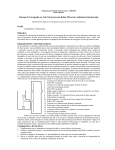
1.3.2 Operating Principle
The operating principle of our non-contact Laser Measurement System (LMS) is
based on time-of-flight measurement. The LMS calculates the distance to the object
using the time of flight of pulsed light, i.e. the length of time between sending and
receiving the beam of light (Figure 1.3.2.1).
An extremely short pulse of light (infrared laser beam) is transmitted towards an
object. Part of the light is reflected back to the unit after a fraction of a second later. A
rotating mirror deflects the pulsed light beam to many points in a semi-circle. The
precise direction is given by an angular sensor on the mirror (laser RADAR). A large
number of coordinates measured in this way are put together to form a model of the
surrounding area's contours. Using the serial interface of the unit, measurements are
transferred in real time (or other specified rates) to a host PC for further evaluation.
Emitter
Receiver
Rotating mirror
Figure 1.3.2.1 : Operating Principle of SICK LMS
72
100° scan
180° scan
LMS
Figure 1.3.2.2 : Scan Angle and Angular Resolution
As seen from Figure 1.3.2.2, the LMS does a planar scan of either 100° or 180° with
an angular resolution choice of 0.25°, 0.5° or 1°. This implies that for a 180° scan
with 0.5° angular resolution, there will be a total of 361 scan values. ((180×2) + 1(0°
value) = 361). Each scan value consists of 2 bytes of data and all these are important
as the LMS will send the number of data bytes according to the request.
73
1.3.3 Specifications (LMS 291-S05)
Dimensions (W×H×D)
155×210×156 (mm)
Maximum Range
80 m (outdoor); 150 m (indoor)
Range (without supplementary
Up to 30 m
reflectors)
Range with minimum reflectivity 1.8%
4m
Lateral Resolution (mm)
10 mm
Angular resolution
100° Scan:
0.25°/0.5°/1°,
No. Of Scan Values: 401/201/101
180° Scan:
0.5°/1°
No. Of Scan Values: 361/181
Configuration by software
Response times
52 ms with angular resolution of 0.25°
26 ms with angular resolution of 0.5°
13 ms with angular resolution of 1.0°
Interfaces
Serial RS-422 or RS-232 switchable
Measurement data
Real-time transfer, binary data
Data transfer rate
9.6 / 19.2 / 38.4 / 500 Kbaud
Voltage supply (electronic)
24 VDC ±15%
Laser Protection Class
1 (Eye -safe)
Table 1.3.3.1: Specifications of SICK LMS 291-S05
74
1.3.4 Features
•
High-resolution measurement system
•
Non-contact, optical measurement over long distances
•
High scanning frequency allows high speed movement of objects
•
An active system, requiring no illumination of the target area
•
No reflectors or markings necessary on target objects
•
Background and supporting medium have no affect on measurements
•
Any orientation of target objects is possible
•
Transfer of measurement data in real time available for further processing or
control functions
•
Self-testing, no external testing procedures required
•
Suitable for outdoor use
1.3.5 Possible Applications for SICK LMS
The LMS can be used for standard applications involving measurement of objects
and position determination, monitoring areas and vehicle guidance and collision
control.
The fundamental ability of laser scanners to offer accurate contour measurement is a
very important asset for use in the above applications. Advanced laser technology is
relatively straightforward to acquire, install and maintain. It can provide the precision,
which adds substantial value to the container handling process.
Collision control is a problem in many areas, for example in the container-handling
terminal. The laser scanner’s function is to monitor one or more zones in front of the
75
fixed path or mobile equipment and to alert an operator of a potential collision; i.e. it
functions as a system designed to avoid collision. This function can be extended to
many other areas like car parking guiding and car following applications.
1.3.6 LMI 400
The LMI (Laser Measurement Interface) is the universal evaluation system for the
distance measurement values generated by the LMS. One or more LMS can be
combined and connected to the LMI to create a single system. It can be flexibly
controlled according to the particular application used. The LMI 400 receives the data
from the LMS in real-time using an asynchronous serial interface so that every scan
can be processed by the LMI. A maximum of 4 LMS sensors can be physically
connected to a LMI.
A LMS (stand-alone) can be connected directly, witho ut an LMI, for diagnosis and
requests for measured values. Thus, in this project, there is no requirement for a LMI.
Figure 1.3.6.1 below illustrates the maximum configuration possible for a LMI
management system.
76
LMS 1
Transmit scan data
under real-time
conditions
LMS 2
HOST
(LINUX PC)
Receives LMS data in real-time
via RS422
Transmit scan data
under real-time
conditions
LMI-SYSTEM
RS422
Communicates with
LMI via RS232/422
Communicates with host via
RS232/422
LMS 3
Transmit scan data
under real-time
conditions
LMS 4
Transmit scan data
under real-time
conditions
Figure 1.3 .6.1 : Maximum Configuration for a LMI System
77
CHAPTER II
IMPLEMENTATION OF REAL-TIME SERIAL INTERFACE
In this chapter, detailed description and explanation of the implementation of a realtime serial interface between MPC555 and SICK LMS will be given. Basically, it will
be split into 3 main parts; the first will explain the real-time serial interface, followed
by the explanation of the serial functions of the MPC555. The final part shall look into
the description and explanation of programming the SICK LMS.
2.1
Real-Time Serial Interface
The present Cycab based on the older Motorola MC68332 microcontroller (without
CAN bus support) is programmed only to handle data transfer rate of 9.6 Kbauds
between the equipped LMS and a laptop. Also, the MC68332 microcontroller does
not have a CAN bus interface, which limits the number of devices that it, can control.
With the new Cycab, the new generation MPC555 microcontrollers can handle up to
a maximum data transfer rate of 1250 Kbauds, which is more than sufficient to have
real-time data transfer between the MPC555 and LMS. To have real-time data
transfer, a minimum baud rate of 500 Kbauds is required.
LIN
UX
PC
(on
Sends command to LMS via
RS422
CAN Bus
(CAN 1)
MPC555
Receives LMS data in real-time
via RS422
LMS
RS422 at
500
Kbaud
Transmit scan data
under real-time
conditions
Figure 2.1.1 : Configuration of Required Serial Interface
78
2.1.1 Serial Interface
The serial interface for the real-time data transfer is of type RS422. However, due to
a hardware incompatibility problem (refer to MPC555 Interface Port) between the port
interface card and the MPC555, RS232 was being used in the project.
RS means Recommended Standard. Both RS232 and RS422 are of full duplex type.
Full duplex devices can transmit and receive data at the same time. The maximum
data speed for a RS232 is about 115 Kbauds while the RS422 can go up to about 10
Mbauds. The RS232/RS422 serial interface used has a Sub-D 9 pin connector and
this is commonly used in interfacing between computer peripherals. Figure 2.1.1.1
shows the front view of a typical Sub-D 9 pin connector that was used.
Figure 2.1.1.1 : Sub-D 9 Pin Connector View
2.1.2 Serial Format
Before commencing with the programming of the real-time serial interface
implementation, the serial format of the data/message frames that MPC555 and
SICK LMS will send/receive must be known. As the 2 hardware are from 2 entirely
different manufacturers, there will always be the possibility of hardware
incompatibility problems. It is very important that both the receiving and transmitting
devices use the same data frame format. With the same data frame format defined,
79
then both hardware can capture and send data successfully based on the defined
format.
All data frames must have a start bit and at least one stop bit. The SCI (Serial
Communication Interface) in MPC555 provides hardware support for both 10-bit and
11-bit frames. In the case of message frames sent by the SICK LMS, a byte of data
consists of 1 start bit, 8 data bits, 0 parity bit and 1 stop bit. With reference to
Table 2.1.2.1 below, the different data frame formats that MPC555 can support is
shown. Thus, basically the messages sent between the 2 devices are in 10-bit frame
format. With the data frame format known, it can thus be specified in the initialisation
of the UART interface in MPC555. Once specified, the MPC555 UART interface will
be able to send and capture data successfully to and from SICK LMS. This will
ensure that the MPC555 gets the correct data byte position.
10-Bit Frames
Start
Data
Parity/Control
Stop
1
7
-
2
1
7
1
1
1
8
-
1
11-Bit Frames
1
7
1
2
1
8
1
1
Table 2.1.2.1: Serial Frame Formats
80
2.2
MPC555 Control Board
2.2.1 UART Serial Interface Functions in C Language
Robosoft had provided some C language libraries specific for the MPC555
microcontroller. The libraries written for the UART serial interface were utilised in the
implementation of the real-time serial interface between the MPC555 and SICK LMS.
The figure 2.2.1.1 below lists out the main functions used in the programming.
Function Declaration
1
Comments
Int UARTInit (int UartNb, int Baud, int nbit, int
Initialise UART serial
nstop, int parity, int ButPtr, int Bufsize)
interface on MPC555.
Return 0 if all is ok.
2
int UARTClose (int UartNb)
Disable UART serial
interface when error is
detected.
3
Int UARTGetChar (int UartNb, char *C)
Return char read from
target (SICK LMS) if any. If
no char is in the buffer,
then return
Err_SCCNoChar.
4
Int UARTGetWaitChar (int UartNb, char *C)
Wait for char read.
5
int UARTPutChar (int UartNb, char x)
Input char to target. Return
0 if all is ok.
Table 2.2.1.1 : MPC555 UART Interface Functions
81
2.2.2 MPC555 Interface Ports
In order for MPC555 to be able to communicate with the LMS, the MPC555’s COM
serial port has to be initialised. The MPC555 control board used in this project has 6
ports: 2 CAN Bus ports, 3 serial ports and 1 free port (refer to Photo 2.2.2.2). The
written program was downloaded into the MPC555 control board via the CAN port 1.
The new Cycab will be based on a Linux PC (Personal Computer) installed with a
CAN Interface Card and all the main nodes of the Cycab will be connected by CAN
bus to the MPC555.
48 VDC Power
Supply
LCD
Screen
CAN
Bus
RS 232 or
RS 422 to
SICK LMS
Photo 2.2.2.1 : MPC555 Control Board with Connections (Top)
However, due to hardware incompatibility between the port interface card and
MPC555, the maximum baud rate that the port can handle is about 250 Kbauds
whereas the minimum baud rate for real-time data transfer must be at least 500
82
Kbauds. Thus, the serial interface was being tested at 19.2 Kbauds instead (until
Robosoft provides a new port interface).
Serial
Free
CAN
SPI
Serial COM 1
CAN Port 1
Photo 2.2.2.2 : MPC555 Control Board with Connections (Front)
83
24 VDC Power
Supply
RS232 or
RS422 from
MPC555
Indicator
lights
Photo 2.2.2.3 : SICK LMS with Connections (Top)
Photo 2.2.2.3 above shows a top view of the SICK LMS attached to the Cycab. It can
be seen that the RS232/RS422 cable from the MPC555 are connected to the right
port of the SICK LMS.
84
2.3
SICK LMS
2.3.1 LMS Telegram Structure
The SICK LMS requires pre-defined telegrams for communication with the Host,
which can either be a computer or in this case, a microcontroller (MPC555). Data is
transferred in binary format (but written and displayed in hexadecimal format) and
transfer is initiated by the STX byte (start of text), 02H. In addition, the transferred
data is also in INTEL data format. This implies that word transfer takes place with the
lower address and the least significant byte first, followed by the bytes of higher
address and significance. The structure of the telegrams sent and received must
comply with the pre-defined telegram structure throughout the entire program.
Otherwise, errors will occur and make troubleshooting difficult. Table 2.3.1.1 below
shows a typical LMS telegram structure and Table 2.3.1.2 describes the structure in
detail.
STX
ADR
Len
CMD Data ……(N bytes)
Table 2.3.1.1 : LMS Telegram Structure
85
Status
CRC
Designation
Data width
Description
(bits)
STX
8
Start byte (02H)
ADR
8
Address of the LMS to be contacted.
Note: The LMS adds the value 80H to the address
when responding to the Host Computer.
Len
16
Number of data bytes (CMD+Data+Status)
CMD
8
Command byte sent to the LMS.
When responding, LMS will send the original command
byte with the addition of 80H to the value.
Data
N×8
Optional, depends on the previous command.
Status
8
Optional, the LMS transmits the status message only
when it is sending out data.
When sending command to LMS, no status message is
transmitted.
CRC
16
CRC checksum for entire data.
Table 2.3.1.2 : Description of LMS Telegram Structure
With reference to the above tables, it can be seen that a typical telegram sent to LMS
consists of the following bytes in sequence: STX, ADR, LEN Low, LEN High, CMD, N
× Data, Status, CRC Low, CRC High. One very important definition to note is the 2
Len bytes, which describes the length of the following data bytes except the CRC
bytes. That means the Len bytes refer to the total number of bytes in CMD, Data and
Status o nly. Caution must be taken not to confuse these data bytes with the actual N
× Data bytes. As the number of Data bytes, N, sent is different every time, thus it is
necessary to read the Len bytes and minus off 2 bytes (CMD and Status) in order to
get the number of Data bytes. In this project, the defined address ADR of the SICK
LMS is 0x01 (01H = 1).
86
2.3.2 Organisation of Telegrams
In order to establish a good communication interface between the SICK LMS and a
Host system (MPC555 in this project), a comprehensive list of different telegrams
doing different functions is required. These telegrams can be organised into 2 main
categories by their direction of data transfer: Host to LMS and LMS to Host.
Subsequently, the telegram list can be furthur categorised into the following different
sub-categories:
•
Telegrams from Host to LMS
♦ Initialisation and Reset of the LMS
♦ Select/Change of operating mode of the LMS
♦ Select/Change of configuration of the LMS
♦ Request for measured (scan) values
♦ Request for LMS status data
♦ Request for LMS configuration data
•
Telegrams from LMS to Host
♦ Response telegrams by LMS with respect to telegrams sent by Host
In addition, when request telegrams are sent from Host to LMS, a software
handshake will be initiated by the LMS. Upon the receipt of a correct request, the
LMS will send out a character ACK (06H) before the entire response message.
However, in the case that an error is detected, the LMS responds with a NAK (15H).
87
For synchronisation purposes, the time interval allowed between 2 bytes of data in a
telegram is between a minimum of 55 µs and a maximum of 6 ms. When violated, the
telegram will be ignored. For a more complete list of telegrams for the LMS, refer to
Appendix A.
2.3.3 Structure of LMS Status Byte
The status byte consists of 8 bits. As seen from the figure below, the status byte
gives useful information like Error encountered if any or other problems like Pollution.
Bit Position
0
Description
Combination of bits 0,1 and 2 are used to produce values 0 – 4.
1
2
Value
Meaning
0
no error
1
info
2
warning
3
error
4
fatal error
3
Bits 3 and 4 produce data source designators.
4
00
LMS –xx1 to –xx4
01
LMI
10
LMS –xx6
11
Reserved
5
State of RESTART input: 1 – HIGH, 0 – LOW
6
Implausible measured value.
7
Pollution
88
Table 2.3.3.1: Description of LMS Status Byte
With the above Table 2.3.3.1, the LMS telegrams sent or received can be interpreted
and verification functions can also be written.
2.3.4 Example of Telegram Transfer
To have a clearer picture of the telegram structure, an example of a sent telegram
and a received telegram, extracted from one of the serial interface test programs
done, is described here.
2.3.4.1
STX
Command sent from MPC555 (Host) to LMS
ADR
02H
00H
Len
LOW
HIGH
0AH
00H
CMD
20H
Data
00H
S
I
C
K
_
L
M
S
53H
49H
43H
4BH
5FH
4CH
4DH
53H
CRC
LOW
HIGH
BEH
C5H
Table 2.3.4.1 : Command Telegram sent from MPC555 to LMS
2.3.4.2
Interpretation of Command Telegram
02H
Start character for intialisation of transmission.
00H
LMS address (Broadcast addr to all LMS)
000AH
Length of data bytes = 10 (CMD+Data)
20H
Command byte for Select/Change of Operating Mode
00H
Operating Mode = Installation mode for config and setting parameter
89
53H … 53H
Installation mode default password = SICK_LMS
C5BEH
CRC16 Checksum return value
Table 2.3.4.2 : Interpretation of Command Telegram
2.3.4.3
ACK
06H
Response sent from LMS to MPC555 (Host)
STX
02H
ADR
Len
CMD
(+80H)
LOW
HIGH
80H
03H
00H
A0H
Data
Status
00H
10H
CRC
LOW
HIGH
16H
0AH
Table 2.3.4.3 : Response Telegram sent from LMS to MPC555
2.3.4.4
06H
Interpretation of Response Telegram
Acknowledge character when response is received correctly within
60 ms. Otherwise, 15H (NAK = Not Acknowledged) will appear.
02H
Start character for intialisation of transmission.
80H
LMS address (Broadcast addr to all LMS) + 80H
0003H
Length of data bytes = 3 (CMD+Data+Status)
A0H
Command byte for Response to Select/Change of Operating Mode
00H
Response Status = Oper Mode change successful
10H
Status byte
0A16H
CRC16 Checksum return value.
Table 2.3.4.4 : Interpretation of Response Telegram
90
An important point to note and remember is that no Status byte is transmitted when a
request command is sent to LMS. The Status byte is included only when the LMS is
transmitting response messages. Also, for responses from LMS, an ACK byte will be
included before the STX byte. The Len bytes when converted from hexadecimal to
decimal give the number of data bytes that are enclosed within the 2 red lines.
2.3.5 CRC16 Checksum and Other Verification Methods
In ensuring transfer reliability, a block check is done at the end of the telegram with a
CRC checksum over the entire data package with CRC 16 polynomial generator.
CRC, Cyclic Redundancy Check is a common method for detecting data
transmission errors. The CRC will perform a mathematical calculation on the data
block to be sent and generates a unique checksum value that represents the content
and organisation of that data. Subsequently, the receiving station also generates a
checksum value of the received data based on the CRC algorithm. Then, both CRC
checksum values at the sending and receiving stations are compared to make sure
that they are the same. If they are different, it can be concluded that errors occurred
during the sending process.
During the software handshake (refer to Chapter 2.3.2, Organisation of Telegrams),
the LMS does nothing if the wrong ADR is used. When the ADR is correct but the
CRC checksum is incorrect, a NAK will be sent. Finally, in the case where both ADR
and CRC checksum is correct, the LMS will respond with ACK.
Another verification method used was to obtain the return values (0 or 1) of certain
functions. For example, in the initialisation of the UART serial interface of the
MPC555, the function UARTInit will return a value 0 if there is no error. Thus, a
91
simple ‘if’ verification statement in the program can help test if the UART is initialised
properly. These verification measures when implemented in the program will help in
easing the task of troubleshooting or debugging as the user will know at which step
the program encountered the error.
92
2.3.6 The Makefile
A makefile is like an instruction book that tells the compiler which library to look for,
which .c program files and .o object files to compile. Also, it indicates the name of the
target files and the executable file that is to be compiled.
In order to download a program into the MPC555, the C program file with extension
.c must first be converted into a format understandable by the downloader. The
Makefile and some libraries provided by Robosoft contain specific functions for
compiling a program to work in MPC555.
The first part of the Makefile works like a normal Makefile. It first compiles the .c
program files into .o object files. Then, the .o object files are furthur compiled into an
ELF binary executable file format. A function, elf2sdxbin, will convert the ELF binary
executable file into a SynDEX binary file format (.bin) understandable by the
downloader. Then, the downloader function, dwnbin, will download the .bin file into
the MPC555. MPC555 will run the program upon receiving the .bin file.
Makefile function
elf2sdxbin
dwnbin
Description
elf2sdxbin [input file] [output file]
dwnbin [input file] [SID]
Table 2.3.6.1 : Description of Makefile Functions of MPC555
Table 2.3.6.1 gives a good description of how the command lines in the Makefile
were written. SID is the ID number of the MPC555 microcontroller. The MPC555
93
given in this project has an ID of 4014H. However, the Makefile requires the user to
input the SID as a decimal value, so SID is actually 16404.
# Sample Makefile Commands
Download :
elf2sdxbin
TEST
TEST.bin
dwnbin
TEST.bin
16404
Figure 2.3.6.1 : Example of Makefile Commands for MPC555 Program
From Figure 2.3.6.1, the sample in this case was taken from one of the test programs
done during the attachment. The C program that was written was TEST.c and after
the initial normal compilation, an ELF binary executable file, TEST, was created. This
was the input file name for the command line elf2sdxbin and the name given for the
output file was TEST.bin. After the SynDEX binary file TEST.bin was created, the
downloader command line, dwnbin, was inserted with the input file name of TEST.bin
and subsequently, the MPC555 ID in decimal. This entire process will take place
when the user does a Make Download command or Makefile command. For the
complete Makefile program, please refer to Appendix E.
94
2.4
The Simulated Environment
The SICK LMS is connected to the MPC555 via RS232/RS422 cable to port COM 1.
The Figure 2.4.1 below illustrates the overview of the entire setup. In the case of this
project, a Linux PC was used in programming, compilation and downloading of the
completed software into the MPC555. Thus, the simulated environment is in fact the
same as the actual environment on the new Cycab.
A FALCO Infinity series computer was used during the testing and simulation process
of the serial interface program. It is mainly used for inputting responses to the
MPC555 and viewing responses from the LMS.
LIN
UX
PC
Sends command to LMS via
RS422
CAN Bus
(CAN 1)
MPC555
Receives LMS data in real-time
via RS422
LMS
RS422 at
38.4Kbau
d
Transmit scan data
under real-time
conditions
RS232 at
38.4Kbau
d
FALCO Infinity
Series
Computer
To input responses
Figure 2.4.1 : Overview of Simulated Environment
95
2.5
The Flow of Program
2.5.1 Data Exchange between SICK LMS and MPC555
In this C program of the implementation of a real-time serial interface, there are a lot
of data flow between the LMS and the MPC555. These exchanges of data may be
confusing and the LMS is programmed in an orderly manner such that the
initialisation, request and receipt of data are in a proper sequence. Basically, the data
exchanges are categorised into the following parts in sequence in the program.
1) The configuration/operating mode data of LMS
2) The specification parameters of LMS measurement
3) The scan values data
Select/Change of configuration/operating mode
MPC555
Interface
Port
ACK
Data of operating mode changed
SI
C
K
Figure 2.5.1.1 : Request for Change in Operating Mode with Response
96
Select/Change of configuration/operating mode
MPC555
Interface
Port
NAK
SI
C
K
Figure 2.5.1.2 : Request for Change in Operating Mode without Response
Request for measured values (continuous)
ACK
Data of successful request of values
MPC555
Interface
Port
Scan values 1
SI
C
K
LMS
Scan values 361
Figure 2.5.1.3 : Request for Scan Values (continuous)
97
Figure 2.5.1.1 shows a flow diagram of a good request for Select/Change of
Configuration/Operating Mode. Upon verifying that the request is good, an ACK byte
is sent followed by the mode changed data. An example of a bad request (with
incorrect CRC) is shown in Figure 2.5.1.2. No data is transferred after the NAK byte
is sent.
For the Request of Scan Values (continuous), the normal procedure takes place
(Figure 2.5.1.3) with the request sent to LMS and after verification, ACK is sent back
to MPC555. Following the ACK, the normal response message describing a
successful request for scan values is sent. After that, the scan values will then be
sent. Depending on the scan angle and the angular resolution chosen, the number of
scan values will differ. For this project, the default scan angle of 180° and angular
resolution of 0.5° was chosen. Thus, 361 scan values will be sent. Refer to Table
1.3.3.1 for details of number of scan values. The retrieving of the 361 values (after a
request for the scan values) will be explained in more detail in the next section 2.5.2,
Main Program Flow.
98
2.5.2 Main Program Flow
UARTInit
(Initialise UART
serial interface of
MPC555)
Return 1
UARTClo
se
Er
Return 0
OK
SICKInit
(Initialise LMS )
Else
Er
Return 0
OK(Msg
sent)
Return 1
SICKChkACK
Er
Return 0
OK
SICKGetMsg
SICK_CRC_Check
Return 0
Return 1
Er
OK
SICKInit2 (Chg of Baud Rate)
Similar Process
Figure 2.5 .2.1 : Initialisation Flow of Main Program
99
SICKInit3
(Request LMS to
send all scan
values continuosly )
Return 1
Er
UARTClo
se
Return 0
OK
SICKChkACK
Return 1
Er
Return 0
OK
SICKGetMsg
SICK_CRC_Check
Return 1
Er
Return 0
OK
SICKGetData
SICK_CRC_Check
Return 0
Return 1
Er
OK
Application/Data
Treatment
Figure 2.5.2.2 : Capturing of Scan Values in Main Program
100
As mentioned earlier in Chapter 2.5.1, the data exchange between SICK LMS and
MPC555 can be categorised into 3 categories and the main program can also be
categorised in the same way. In Figure 2.5.2.1, the initialisation of the UART interface
of MPC555 and SICK LMS is shown and this is the first part of the main program.
The UART was first initialised (by UARTInit) and if the return value is a 0, it means
that the UART was initialised properly. From the program, the function declaration is
UARTInit (0, 19200, 8, 1, 0, &Buffer, BufSize). In sequence, 0 refers to the serial
COM 1 port number of the MPC555 control board; 19200 refers to the desired baud
rate; 8 is the number of data bits; 1 is the number of stop bit and finally 0 is the
number of parity bits. &Buffer is the pointer to the declared buffer while BufSize is the
size of the buffer which had been declared to be 128 bytes in the beginning of the
program.
After the UART was initialised, the program continues to the next step of sending a
command string, SICKInit, to the LMS. This is to initialise the LMS with specifications
corresponding to that of the MPC555 UART serial interface. With reference to the
program, the LMS telegram structure (Table 2.3.1.2) and the LMS telegram list, the
initialisation telegram SICKInit can be interpreted. However, the array init[16] was
declared with a size of 16 bytes but only 14 bytes were included. The reason is the
last 2 bytes are reserved for the CRC bytes and they are created by the function
SICKCreateCRC. The block of data from the 1 st byte to the 14th byte are included in
the SICKCreateCRC calculation. After that, the CRC Low byte is put into init[14] and
CRC High byte into init[15]. This is because data is transferred in INTEL data format
for SICK LMS.
101
The next step in the program is the function SICKChkACK where it will capture the 1 st
response byte and determine if it is an ACK byte. If so, it will continue capturing the
rest of the message by SICKGetMsg. Otherwise, if it is a NAK or rubbish, error has
occurred and the program will proceed to UARTClose (0) where the UART interface
of the MPC555 will be closed. After getting the entire message, the function
SICK_CRC_Check will create a CRC value based on the entire message block
except the received CRC bytes. Then, the received CRC bytes will be converted into
decimal format (CRCL + (CRCH x 256)). Both received and created CRC values will
be compared and if they are the same, the program will continue.
Following command strings are sent to control the LMS to commence with a scan
(180° scan and 0.5° angular resolution by default) and to send back the scan data
(361 values) to the MPC555.
Figure 2.5.2.2 shows the process of capturing the 361 scan values in the main
program. First of all, SICKInit3 is sent with the request of all the scan data values
(continuous). The same process as the earlier functions is run though: SICKChkACK,
SICKGetMsg and SICK_CRC_Check. This time, after the MPC555 receives the
message that the request for all 361 scan values was successful (by SICKGetMsg),
the sending will not stop there. The LMS will proceed to send another string of data
beginning with STX (no ACK or NAK byte for this) and this string contains all the 361
values. Also, since each scan value consists of 2 bytes, the total length of the entire
string is (361x2)+4 = 726 bytes. The additional 4 bytes are the CMD, Status, LENL
and LENH.
102
After getting the entire string of scan values, a CRC check is done again and then the
program will go to the next part: treatment of the scan values for Application
programs like Car Following and Obstacle Avoidance. The complete program on the
serial interface can be found in Appendix D.
103
CHAPTER III
PROCESSING
OF
SCAN
DATA
AND
APPLICATION PROGRAM
In this third Chapter, the report will focus on the method of data extraction for
processing and the application programs : Obstacle Avoidance and Car Following. A
researcher did before some previous work on the above for the old Cycab equipped
with the MC68332 microprocessor. The objective now is to translate these into a
suitable format for the MPC555 microcontroller installed in the new Cycab.
3.1
Obstacle Avoidance
3.1.1 LMS Programmable Scanning Field
As explained earlier in the Chapters 1 and 2, the SICK LMS can be requested to
change its operating mode, baud rate, type of data to be sent, method of data
sending (e.g. continuous) and many others. In fact, the LMS can be instructed to
define its scanni ng field. Figure 3.1.1.1 below illustrates 4 possible configurations of
scanning field. Configuration 1 is the normal configuration where the laser from LMS
makes either a 100° or 180° scan. Configuration 2 and 4 are a defined scanning field
where a desired area is ‘marked-out’. The LMS can be programmed to define the
scanning field in a rectangular field or a semi-circular field. Furthermore, up to 3
scanning fields can be configured active simultaneously and this is shown as
configuration 3.
1
2
104
3
4
Figure 3.1.1.1 : Possible Configurations of LMS Scanning Field
3.1.2 Implementation of Obstacle Avoidance
The purpose of an Obstacle Avoidance application is to implement a safety feature to
the Cycab, where it will either stop or move out of the way when an obstacle is
detected. This application is simple in terms of data extraction and processing, as it
does not need special processing of the scan data.
It can be seen in configuration 4 of Figure 3.1.1.1 above, the LMS was programmed
to scan a designated area in front of it. For example, an area of 5 m by 5 m can be
defined and to increase the safety distance of the Cycab, a bigger field can be
defined. The size of the field can be easily defined by sending the request te legram
to the LMS.
Then, the Obstacle Avoidance will be programmed to check for a change in the scan
data received. As soon as an obstacle is within the defined field boundary, the
program will detect a change and send a request to the MPC555 subsequently to
either stop the vehicle or steer away.
3.2
Car Following
3.2.1 Extraction and Processing of Data
105
For sophisticated and complicated application like Car Following, it is necessary to
retrieve and process the scan data values. When the LMS sends the scan values
back to the Host (MPC555), it is capable of sending the data in different format/type.
All the measured data sent by the SICK LMS come from the following information :
•
The angle of emitting laser beam
•
The distance
•
The level of intensity of the reflected beam
The data processing by the LMS will provide the following information :
•
Data values of 1 complete scan in polar coordinates and the intensity level of
the reflected beam
•
Averaged values
•
Partitioned values
•
Averaged partitioned values
•
The shortest perpendicular distance with respect to the radius of the scan
•
The shortest distance value in each segment
•
Cartesian coordinates
Figure 3.2.1.1 below illustrates a typical process of the extraction and processing of
scan data by the LMS.
Selection
Scan
of data
Filtering of
required
data
format to
106
Processin
g of data
Data
Figure 3.2.1.1 : Extraction and Processing of Data
3.2.2Detection of Reflector Target
The SICK LMS detects the distance of objects in front of it by the principle of time-offlight as explained in Chapter 1.3.2. This implies that the total time taken for the
emitted laser beam to reach the target and for the reflected laser beam to return to
the captor, multiplied by the speed of light constant will produce the distance. Though
the SICK LMS is able to detect most objects in front of it, the intensity of the reflected
laser beam detected by it is much weaker than the emitted laser beam. This also
implies that the SICK LMS may not be able to detect objects of certain material very
well. Thus, poor reflectors of light may not be well detected and do not make good
targets.
For the Car Following application, the objective is to program the SICK LMS to detect
another Cycab in front, so that the 2nd Cycab will follow the leading one. In order to
have a higher intensity reflected laser beam, 2 special light reflecting targets were
placed behind the Cycab. Then, the position of the 2 reflector targets (back of the
Cycab) can be easily detected, as they will produce a very high intensity of reflected
laser beam compared to the surrounding environment.
3.2.3Mathematical Algorithm
For the application program of Car Following, the following 3 data are necessary :
•
Angular position a of the target (centre of the Cycab)
•
Distance d of the target
•
Angle ?, the relative orientation of the axis of the 2 vehicles
107
y1
C1
dc
Leadi
ng
Cycab
B
y
y2
C2
d1
d
d2
θ
α1
α
LMS on
Following
α2
x1
x
x2
Figure 3.2.3.1 : Mathematical Diagram Representation of Car Following
As illustrated in Figure 3.2.3.1, C1 and C2 are the centres of the 2 reflector targets
fixed to the back of the leading Cycab. In order to obtain the 3 data a, d and ? for the
Car Following application, the following equations derived from Figure 3.1.2.1 were
used.
x1 = d1(cosa1)
x2 = d2(cosa2)
y1 = d1(sina 1)
y2 = d2(sina 2)
dc = v[(x1 – x2 )2 + (y1 – y2 )2]
x = (x1 + x2 )/2
y = (y1 + y2 )/2
a = (a1 + a2)/2
? = -argsin[(y2 – y1)/dc]
108
where
x and y : Cartesian coordinates of the leading vehicle (relative to the following
vehicle)
d : Direct distance between the 2 vehicles (with respect to the centre of the vehicle)
? : Angle between the longitudinal axis of each vehicle
a : Angular position of the leading vehicle with respect to the front of the following
vehicle
dc : Distance between the 2 reflector targets, C 1 and C 2
The program will filter aside all the required values like the Cartesian coordinates in
order to get the 3 required values for Car Following application.
Both applications are currently in the process of implementation.
109
CHAPTER IV
COMMENTS AND DISCUSSIONS
4.1
Limitations of SICK LMS
The current laser sensor used, SICK LMS, conducts a scan of up to 180° and a high
angular resolution of 0.25°. It is configurable from the type of scanning field required
to the type of scan data value the user wants to retrieve. However, its drawback is
that the scan is only in planar form. Thus, the laser scanning zone is like a flat piece
of paper cutting across the area in front. This may pose some problems like the
height of obstacles or reflecting beacons must not be too short or too high. They must
coincide with the line of sight of the LMS laser beam. This problem was actually
encountered when tests were done on the Cycab. The securing screws on the SICK
LMS that attaches the LMS to the front of Cycab are not tight enough.
This problem, along with the weight of the LMS, pulls and tilts the LMS down. Though
the range of tilt is not big (less than 1 cm) at the point of attachment, this difference in
height is greatly magnified at a further distance from the Cycab. This caused the
inability of the laser to reach the desired target. If the tilt height difference is greater
than the height of the reflector target (of the leading Cycab) in a Car Following
application, the LMS will not be able to detect the reflectors and the application will
fail.
Therefore, a proposed solution would be to increase the overall reflector height or to
implement a more secure attachment system for the SICK LMS.
110
Furthermore, with scan data from a planar scan, it is only possible to plot out a 2Dimensional (2D) plan of the specified scanning field. Though a 2D plan may prove
just sufficient for Obstacle Avoidance application, the user will not be able to know
the obstacle’s size, shape and other features that may allow the user to have more
decision making choices. For example, if a large truck is in front of the Cycab, the
user may either want the Cycab to slow down and keep a longer safety distance, or
take another available route. Thus, a simple 3-Dimensional (3D) plan model of the
specified scanning field can provide much more data and extend the uses of the
application further. Pattern comparison (e.g. compares the shape, size of obstacle)
can then be incorporated and provide information like the nature of the obstacle.
These shall be feedback to the Cycab, which will make decisions based on it.
4.2
Processing Time
Time is a very important factor in decision-making and it applies to the application
programs of the Cycab as well. The SICK LMS does a scan within a certain time and
this time depends on the scan angle and angular resolution. For example, in this
project where the LMS is requested do a 180° scan with an angular resolution of
0.5°, the time taken to complete a scan is 26 ms. However, the time required
increases as the angular resolution increases.
The overall objective of the Cycab is to have application programs that guide it safely
and yet fast enough to satisfy the needs of people for public transport. Thus, if the
response time for MPC555 to complete a task (e.g. To avoid an oncoming obstacle)
is too long (> 500 ms), the vehicle may not perform as predicted to avoid the obstacle
111
in time. In order to curb this problem of long processing time, it will be better to keep
the program in MPC555 to a suitable length.
4.3
Addition of a User Menu
The current program done for the serial interface between MPC555 and SICK LMS is
a simple one. As can be read from the report, the LMS has a lot of functions and
each request and response corresponds to a different telegram, so it will be better if a
user menu with all the different requests is included in the program. With this menu,
the program will be user-friendlier and running of the application programs can also
be included in the menu.
4.4
Minor Problems Encountered
During the course of work with the SICK LMS, there were often instances of
insufficient power to power the LMS. In fact, the LMS is a big consumer of energy
and this actually shortens the life span of the battery run time. Thus, it is suggested
that the battery of the Cycab be recharged after it is being used for a fixed period of
time.
For the MPC555, it has a problem of hardware reset not working. Sometimes, when a
program ‘hangs’ midway while processing in the MPC555, doing a hardware reset of
the MPC555 will not reset and clear all the buffers. Power to the MPC555 has to be
cut off completely for a few minutes before the MPC555 can operate again. This
problem will be reported to Robosoft for their action.
112
CHAPTER V
INRIA Rhone-Alpes
CHAPTER V
SUMMARY AND CONCLUSION
For this period of Industrial Attachment with INRIA Rhone-Alpes, the project given
was very good with a clear objective and direction. Till this moment, the goal of
implementing a high-speed serial interface between the MPC555 and the SICK LMS
had been achieved. Although tests at the initially proposed 500 Kbauds were not
carried out (due to problems with the MPC555 board provided), tests at lower baud
rates were done under the direction of my supervisor. Also, the program written to
implement the serial interface works well at the other lower baud rates, so there
should not be much problem for real-time interfacing.
The next objective of implementing application programs (Obstacle Avoidance and
Car Following) for the Cycab is currently being carried out. These applications involve
programming the MPC555 and the SICK LMS to conduct and collect different scan
data, thereby making use of the implemented serial interface too. These
implementations of application programs will be achieved by the end of the
attachment.
Due to the numerous functions that the SICK LMS can do, there were a lot of
confusion and doubts over the functions of the telegrams. However, tests done while
implementing the serial interface provided results that helped clear some of the
doubts and they were documented in this report as well.
On the whole, this project involving both hardware and software implementation has
been very fruitful. A lot of experience was gained in working with hardware interfacing
and the hardware/software implementation. Due to the different nature of the
56
CHAPTER V
INRIA Rhone-Alpes
hardware involved, it was necessary to have a clear basic understanding of them in a
very short time. This taught me the skills of filtering out the more important theory and
information whenever there is a need to work with new hardware. In addition, the
importance of good and clear documentation of hardware specifications, theory and
correct procedures was also appreciated. A good documentation will be very useful
to fellow researchers working on follow-up projects.
Working as a junior researcher also allowed me to experience the working
environment of a researcher. Everyone in the same project group contributes to the
final goal of the project. For example, the Cycab is quite a big project that involves
many researchers. From the mechanics and electronics of the vehicle, linear camera
guiding to the serial interfacing of the SICK LMS, all these contributions are all made
by different researchers with the same final aim. Therefore, teamwork is very
important in research.
Finally, this report was written to be as clear and concise as possible, with the aim of
serving as a guide to anyone who will be working on similar or follow-up projects.
57
APPENDIX A
INRIA Rhone-Alpes
REFERENCES
Cycab
[1]
INRIA Homepage
http://www.inria.fr
[2]
INRIA Rhone -Alpes Homepage
http://www.inrialpes.fr
[3]
Project LARA / Cycab Web page
http://www-lara.inria.fr/cycaba/
MPC555
[4]
Motorola Homepage
http://e-www.motorola.com
[5]
Motorola, “MPC555 User Manual”
[6]
Motorola, “MPC555 Evaluation Board, Quick Reference”
SICK LMS
[7]
SICK Homepage
http://www.sick.fr/
[8]
SICK, “LMS/LMI 400 – Definition of telegrams between the user interface and
LMS or LMI systems via RS 422/RS 232”
[9]
SICK, “User software, LMS/LMI, Laser Measurement System”
Others
[10]
Robosoft Homepage
http://www.robosoft.fr/
[11]
Cross GCC Web page
http://www.gnu.org/software/gcc/gcc.html
A1
APPENDIX A
[12]
INRIA Rhone-Alpes
M. Riess, “Qualification d’un télémètre à balayage laser pour la robotique
mobile: Intégration et experimentations” (Study of Functions of a Laser
Scanner for Mobile Robots: Experiments and Implementations)
A2
APPENDIX A
INRIA Rhone-Alpes
APPENDIX A
Telegram Number
Description
0x10
Initialisation and reset of LMS
0x20
Select/Change of LMS operating mode
0x30
Request for measured values
0x31
Request for sensor status
0x32
Request for error telegram
0x36
Request for averaged measured values
0x37
Request for partitioned measured values
0x3A
Request for LMS type
0x3B
Change of LMS variant
0x3F
Request for averaged partitioned measured values
0x40
Configuration of LMS capture fields
0x41
Change of active field group
0x45
Request for configured field
0x74
Read LMS configuration
0x76
Request for measured values in cartesian coordinates
0x77
Define LMS-2xx-xxx06 configuration
Table A1 : Telegram List for Data Exchange from Host to
LMS
A3
APPENDIX A
INRIA Rhone-Alpes
Telegram Number
Description
0x90
Message sent by LMS after Power On
0x91
Confirmation of software reset telegram
0x92
Not acknowledged, NACK (for invalid commands)
0xA0
Response to change of operating mode
0xB0
Response to request of measured values
0xB1
LMS sensor status
0xB2
Error message/test message
0xB6
Send averaged measured values
0xB7
Send partitioned measured values
0xBA
Information on LMS type
0xBB
Response to change of LMS variant
0xBF
Send averaged partitioned measured values
0xC0
Response to field configuration
0xC1
Change active field group
0xC5
Configuration data for programmed fields
0xF4
Current LMS configuration
0xF6
Response to request for measured values in cartesian
coordinates
0xF7
Response to definition of LMS-2xx-xx06 configurartion
Table A2 : Telegram List for Data Exchange from LMS to
Host
A4
APPENDIX B
Initial Set-Up Test Program provided by Robosoft
/******************************************************************************************
/* Test.C :Test de l'ensemble TPU, PWM, etc...
/* channel number to test (0..3); the procedure will measure an average on
/* the channel. (Set with nMoy)
/*-------------------------------------------------------------------------------------------------------/* Version: 1.00, 22/10/1999
/*--------------------------------------------------------------------------------------------------------
*/
*/
*/
*/
*/
*/
*/
void InterruptHandlerCAN0(void)
{
}
void InterruptHandlerCAN1(void)
{
}
void InterruptHandlerSPI(void)
{
}
void InterruptHandler2(void)
{
}
void InterruptHandler6(void)
{
}
void InterruptHandler7(void)
{
}
void InterruptHandlerPIT(void)
{
/* Blink the LED as SetLED will return the previous LED state */
SetLED(!(SetLED(0)));
}
/*-------------------------------------------------------------------------------------------------------- */
/* Interrupt handler reserved for EXTERNAL IRQ lines
*/
/*-------------------------------------------------------------------------------------------------------- */
void InterruptHandlerIRQ0(void)
{
}
B1
void InterruptHandlerIRQ1(void)
{
}
void InterruptHandlerIRQ2(void)
{
}
void InterruptHandlerIRQ3(void)
{
}
void InterruptHandlerIRQ4(void)
{
}
void InterruptHandlerIRQ5(void)
{
}
void InterruptHandlerIRQ6(void)
{
}
void InterruptHandlerIRQ7(void)
{
}
/*-------------------------------------------------------------------------------------------------------- */
/* UART Routine : To put a string of char via UART
*/
/*-------------------------------------------------------------------------------------------------------- */
/* Error, the combination Parity + nBit + nStop is not equal to 9 or 10 */
/* (10 and 11 bit frame with Start bit)
*/
#define err_UARTFrame -1
#define err_UART
-2
/* Error UART number must be 0 or 1 */
#define err_UARTNoChar -1
/* NO Char present in the buffer */
int UARTPutString(int UartNb, char *St)
{
int Result = 0;
while ((St[0] != 0) && (Result == 0)) {
Result = UARTPutChar(UartNb, St[0]);
St++;
}
return (Result);
}
B2
/*-------------------------------------------------------------------------------------------------------- */
/* LCD Routine : To display a string of char on LCD screen
*/
/*-------------------------------------------------------------------------------------------------------- */
int LCDPutString(char *St)
{
int Result = 0;
while ((St[0] != 0) && (Result == 0)) {
Result = LCDPutChar(St[0]);
St++;
}
return (Result);
}
/*-------------------------------------------------------------------------------------------------------- */
/* LCD Command: see documentation of HDD44780
*/
/*-------------------------------------------------------------------------------------------------------- */
#define lcd_Clear
0x01
#define lcd_CursorHome
0x02
#define lcd_SetAddress
0x80
#define lcd_SetAddrL1Home
0x80
#define lcd_SetAddrL2Home
0xC0
#define err_ErrorLCD
-1
/* Error returned when busy flag is ALWAYS set */
/*-------------------------------------------------------------------------------------------------------- */
/* ADC channel assignment: see schematic for more detail
*/
/*-------------------------------------------------------------------------------------------------------- */
#define adc_VAxe1
#define adc_VAxe2
#define adc_VAxe3
#define adc_VAxe4
#define adc_Temperature1
#define adc_Temperature2
#define adc_Temperature3
#define adc_Temperature4
8
9
10
11
12
13
14
15
/*-------------------------------------------------------------------------------------------------------- */
#define BufSize 16
#define nMoy 64
/* Buffer Size */
/* Average number */
int main()
{
char Buffer[BufSize];
char Ch;
char St[31];
/* For RX */
B3
int VMoy[nMoy];
int Val, Value;
int I, J;
int chAdc;
int axis;
int EncVal;
short int pwmcmd = 0;
int direc;
ADCInit();
LCDInit();
TPU3Init();
PWMInit();
// InitInterrupt(0x800);
UARTInit(0, 9600, 8, 1, 0, &Buffer, BufSize);
UARTPutString(0, " \n\rUART 9600 Baud, ADC Chain calibration by Robosoft SA");
LCDPutString("PoKkIaM & MpC555!");
chAdc = 0;
for (I = 0; I < nMoy; I++) {
VMoy[I] = 0;
}
Value = 0;
I = 1;
while (1) {
DACWrite(0, I);
DACWrite(3, (-I & 0xFFF));
DACWrite(1, 0x0400);
I = I + 10;
I = I & 0xFFF;
ADCRead(chAdc + adc_VAxe1, &Val);
Val = Val - 512;
Value = Value - VMoy[nMoy - 1];
for (J = nMoy - 1; J > 0; J--) {
VMoy[J] = VMoy[J - 1];
}
VMoy[0] = Val;
Value = Value + VMoy[0];
Val = Value / nMoy;
B4
if (UARTGetChar(0, &Ch) != err_UARTNoChar) {
if (Ch == '+')
POTSet(chAdc, +1);
if (Ch == '-')
POTSet(chAdc, -1);
UARTPutChar(0, Ch);
}
direc = 0x0F;
EncRead(0, &EncVal);
if (EncVal != 0)
UARTPutChar(0,'X');
if (UARTGetChar(0, &Ch) != err_UARTNoChar) {
if (Ch == '1')
pwmcmd++;
if (Ch == '2')
pwmcmd--;
if (Ch == 'd')
direc = ~direc;
WritePWMIO(direc);
UARTPutChar(0, Ch);
PWMWrite(0, &pwmcmd);
}
}
return 0;
}
B5
APPENDIX C
Serial Interface Test Program
/******************************************************************************************
/* Test_Serial.c : UART Interface Test Platform
/* Author : Tan Pok Kiam, Moyens Robotique
/* INRIA Rhone-Alpes
/* To test send request, receive response & determine response byte position
/******************************************************************************************
*/
*/
*/
*/
*/
*/
#include <math.h>
#define BufSize 128
int UARTPutString(int UartNb, char *St)
{
int Result = 0;
while ((St[0] != 0) && (Result == 0)) {
Result = UARTPutChar(UartNb, St[0]);
St++;
}
return (Result);
}
int LCDPutString(char *St)
{
int Result = 0;
while ((St[0] != 0) && (Result == 0)) {
Result = LCDPutChar(St[0]);
St++;
}
return (Result);
}
int main () {
char Buffer[BufSize];
char c = 0;
double d;
int i,res;
unsigned char init [7] = {0x02,0x00,0x01,0x00,0x10,0x00,0x00}; /* Test Request */
UARTInit(0, 19200, 8, 1, 0, &Buffer, BufSize);
LCDInit();
LCDPutString("Part1 OK");
/* MPC555 UART Initialisation OK */
for(i=0;i<10000;i++)
d = cos(d);
LCDInit();
for (i=0; i<16; i++)
{
res = UARTPutChar (0, init [i]);
if (res != 0)
{
LCDPutString("Request ERROR");
}
};
LCDInit();
LCDPutString("Part2 OK");
/* Test Request Send Successful */
C1
for(i=0;i<10000;i++)
d = cos(d);
LCDInit();
for (i=0; i<10; i++)
{
LCDPutChar('-');
res = UARTGetWaitChar(0, &c);
/* Receive Test Response */
if (res != 0)
{
LCDPutString("Receive ERROR");
}
LCDPutChar (c);
}
LCDInit();
LCDPutString("Part 3 OK");
/* Message Receive Successful */
for(i=0;i<10000;i++)
d = cos(d);
}
C2
APPENDIX D
Completed Program for Serial Interfacing MPC555 and SICK LMS
/****************************************************************************************** */
/*::::::::::::::::SERIAL INTERFACE BETWEEN MPC555 & SICK LMS::::::::::::::::::::*/
/*::::::::::::::::::::::::::::::::FOR REAL-TIME DATA TRANSFER:::::::::::::::::::::::::::::::::: */
/*:::::::::::::::::::::::::::::::::::::::::::Tested At 19200 Bauds:::::::::::::::::::::::::::::::::::::::::::: */
/*
Filename : Serial1.c
/*
Author : Tan Pok Kiam, Moyens Robotique, INRIA Rhone-Alpes
*/
/*
Created : 04/2001
/*
/****************************************************************************************** */
#include <math.h>
#define BufSize 500
#define Max_Length 1000
int i,res;
char msg[Max_Length];
char data[Max_Length];
unsigned char CrcL,CrcH;
unsigned char LenL,LenH;
unsigned int Len,Crc_Create_Send;
/****************************************************************************************** */
/*
UARTPutString : To send a string of char using MPC555 UART
*/
/****************************************************************************************** */
int UARTPutString(int UartNb, char *St)
{
int Result = 0;
while ((St[0] != 0) && (Result == 0))
{
Result = UARTPutChar(UartNb, St[0]);
St++;
}
return (Result);
}
/****************************************************************************************** */
/*
LCDPutString : To send a string of char to LCD screen of MPC555 board */
/****************************************************************************************** */
int LCDPutString(char *St)
{
int Result = 0;
while ((St[0] != 0) && (Result == 0))
{
Result = LCDPutChar(St[0]);
St++;
}
return (Result);
}
/****************************************************************************************** */
/*
LCDClear : Clear LCDScreen (Modification Required)
*/
/****************************************************************************************** */
D1
*/
*/
*/
void LCDClear()
{
char c = 0;
while(c != 4)
{
UARTGetWaitChar(1,&c);
UARTPutChar(1,c);
}
LCDInit();
LCDPutString("
");
LCDInit();
}
/****************************************************************************************** */
/* SICKCreateCRC : Create CRC16 CHECKSUM for response msg from LMS
*/
/****************************************************************************************** */
#define CRC16_GEN_POL 0x8005
#define MKSHORT(a,b) ((unsigned short)(a)|((unsigned short)(b)<<8))
unsigned short SICKCreateCRC(unsigned char *CommData,unsigned int uLen)
{
unsigned short uCrc16;
unsigned char abData[2];
uCrc16 = 0;
abData[0] = 0;
while (uLen--)
{
abData[1] = abData[0];
abData[0] = *CommData++;
if(uCrc16 & 0x8000)
{
uCrc16 == (uCrc16 & 0x7fff)<<1;
uCrc16 ^= CRC16_GEN_POL;
}
else
{
uCrc16 <<= 1;
}
uCrc16 ^= MKSHORT (abData[0],abData[1]);
}
return(uCrc16);
}
/****************************************************************************************** */
/*
SICK_CRC_Check : CRC checking function for responses from SICK
*/
/****************************************************************************************** */
int SICK_CRC_Check()
{
unsigned int Crc_Create,Crc_Recvd;
Crc_Create = SICKCreateCRC(&msg[0],(Len+4));// Create CRC for msg from STX - Status
Crc_Recvd = CrcL + (CrcH*256);
if (Crc_Recvd == Crc_Create)
{
LCDPutString("CRC_Check Correct");
LCDClear();
return 0;
D2
}
else
{
LCDPutString("CRC_Check ERROR!");
LCDClear();
return 1;
}
}
/****************************************************************************************** */
/*
SICKInit : SICK LMS Initialisation. Change to "installation mode".
/*
Default Password = SICK_LMS
/*
20H--Select/change operating mode.
/****************************************************************************************** */
int SICKInit()
{
for(i=0;i<16;i++)
{
unsigned char init [16] = {0x02,0x01,0x0A,0x00,0x20,0x00,0x53,0x49,0x43,
0x4B,0x5F,0x4C,0x4D,0x53};
Crc_Create_Send = SICKCreateCRC(&init[0],(14));
init[14] = (unsigned char)(Crc_Create_Send & 0xFF);
init[15] = (unsigned char)(Crc_Create_Send >> 8);
res=UARTPutChar(0,init[i]);
if (res == 0)
{
LCDPutString("Msg Sent to SICK");
LCDClear();
}
else
{
LCDPutString("Msg Send Error");
}
}
return res;
}
/****************************************************************************************** */
/* SICKInit2: SICK LMS Command String2. Change baud rate to 19200 Baud.
*/
/****************************************************************************************** */
int SICKInit2()
{
for(i=0;i<8;i++)
{
unsigned char init2 [8] = {0x02,0x01,0x02,0x00,0x20,0x41};
Crc_Create_Send = SICKCreateCRC(&init2[0],(6));
init2[6] = (unsigned char)(Crc_Create_Send & 0xFF);
init2[7] = (unsigned char)(Crc_Create_Send >> 8);
res=UARTPutChar(0,init2[i]);
if(res == 0)
{
LCDPutString("Msg Sent to SICK");
LCDClear();
}
else
{
LCDPutString("Msg Send Error");
}
D3
*/
*/
*/
}
return 0;
}
/****************************************************************************************** */
/* SICKInit3: SICK LMS Command String3. Request LMS to send all scan
*/
/* continuously.
/****************************************************************************************** */
int SICKInit3()
{
for(i=0;i<8;i++)
{
unsigned char init3 [8] = {0x02,0x01,0x02,0x00,0x20,0x24};
Crc_Create_Send = SICKCreateCRC(&init3[0],(6));
init3[6] = (unsigned char)(Crc_Create_Send & 0xFF);
init3[7] = (unsigned char)(Crc_Create_Send >> 8);
res=UARTPutChar(0,init3[i]);
if(res == 0)
{
LCDPutString("Msg Sent to SICK");
LCDClear();
}
else
{
LCDPutString("Msg Send Error");
}
}
return 0;
}
/****************************************************************************************** */
/* SICKChkACK: To check the 1st byte of the response message for ACK
*/
/****************************************************************************************** */
#define ACK 0x06
#define NAK 0x15
int SICKChkACK()
{
unsigned char ack;
ack = 0x00;
UARTGetChar(0,&msg[0]);
ack = msg[0];
while ((ack != ACK) && (ack != NAK))
{
LCDPutString("ChkACK Err:XX");
LCDClear();
return 1;
}
if (ack == NAK)
{
LCDPutString("ChkACK Err:NAK");
LCDClear();
}
else
//ack == ACK
{
msg[0] = 0;
return 0;
D4
*/
}
}
/****************************************************************************************** */
/*
SICKGetMsg: To get the entire response message from LMS
*/
/****************************************************************************************** */
void SICKGetMsg()
{
UARTGetChar(0,&msg[0]);
UARTGetChar(0,&msg[1]);
UARTGetChar(0,&msg[2]);
UARTGetChar(0,&msg[3]);
// STX
// ADR
// LENL
// LENH
LenL,LenH,Len = 0x00;
LenL = msg[2];
LenH = msg[3];
Len = LenL+(LenH*256);
// Convert HEX to DEC
for(i=0;i<Len+2;i++)
// CMD+(N x Data)+Status+CRCL+CRCH
UARTGetChar(0,&msg[i+4]);
CrcL = msg[Len+5];
CrcH = msg[Len+6];
}
/****************************************************************************************** */
/*
SICKGetData: To get the useful scan data values (361 values)
*/
/****************************************************************************************** */
#define STX 0x02
int SICKGetData ()
{
UARTGetChar(0,&data[0]);
// STX
if(data[0] != STX)
{
LCDPutString("GetData Err:STX");
LCDClear();
UARTClose(0);
}
UARTGetChar(0,&data[1]);
// ADR
UARTGetChar(0,&data[2]);
// LENL
UARTGetChar(0,&data[3]);
// LENH
if((data[2] != 0xD6) && (data[3] != 0x02))
{
LCDPutString("GetData Err:Len");
LCDClear();
UARTClose(0);
}
LenL,LenH,Len = 0x00;
LenL = data[2];
LenH = data[3];
Len = LenL+(LenH*256);
UARTGetChar(0,&data[4]);
// CMD
for(i=0;i<Len-1;i++)
UARTGetChar(0,&data[i+5]);
// data
UARTGetChar(0,&data[Len+5]);
UARTGetChar(0,&data[Len+6]);
CrcL = data[Len+5];
D5
CrcH = data[Len+6];
}
/******************************************************************************************
/*-------------------------------------------------------------------------------------------------------/*
Start of main program
/*-------------------------------------------------------------------------------------------------------/******************************************************************************************
*/
*/
*/
*/
*/
int main ()
{
char Buffer[BufSize];
int Response;
UARTInit(1,19200,8,1,0,&Buffer,BufSize);
/* For communication with another terminal to show certain responses */
Response = UARTInit(0, 19200, 8, 1, 0, &Buffer, BufSize);
if (Response == 0)
{
LCDInit();
LCDPutString("UARTInit OK");
UARTPutString(1,"\n\rHello, UART Serial Interface PERFECT!");
UARTPutString(1,"\n\rPress Ctrl-D to continue");
LCDClear();
LCDPutString("Start SICKInit");
LCDClear();
}
else
{
LCDInit();
LCDPutString("UARTInit Error");
UARTClose(0);
}
/**********
Commence SICK Initialisation and Recv Data ***************
if(!SICKInit())
{
LCDPutString("Part1 ok"); //Trial For FALCO
if(!SICKChkACK());
SICKGetMsg();
LCDPutString("Part2 ok"); //Trial For FALCO
if(SICK_CRC_Check() == 0)
//CRC16 Check
{
LCDPutString("Rep1 Rcvd OK");
LCDClear();
if(!SICKInit2());
if(!SICKChkACK());
SICKGetMsg();
if(SICK_CRC_Check() == 0)
{
LCDPutString("Rep2 Rcvd OK");
LCDClear();
if(!SICKInit3());
if(!SICKChkACK());
SICKGetMsg();
SICK_CRC_Check();
if(SICK_CRC_Check() == 0)
{
D6
*/
LCDPutString("Rep3 Rcvd OK");
LCDClear();
SICKGetData();
if(SICK_CRC_Check() == 0)
{
LCDPutString("Scan Values Rcvd");
LCDClear();
}
else
{
LCDPutString("Val rcvd error");
LCDClear();
UARTClose(0);
}
}
else
{
LCDPutString("Rep3 Error!");
LCDClear();
UARTClose(0);
}
}
else
{
LCDPutString("Rep2 Error!");
LCDClear();
UARTClose(0);
}
}
else
{
LCDPutString("Rep1 Error!");
LCDClear();
UARTClose(0);
}
}
}
D7
APPENDIX E
The Makefile
#
#
#
#
#
#
****************************************************************************************
(c) ROBOSOFT ([email protected])
This is a Makefile used to compile programs for MPC555 targets.
Modified : Tan Pok Kiam, Moyens Robotique, INRIA Rhone-Alpes
*****************************************************************************************
SHELL = /bin/sh
.SUFFIXES = .s .c .o
RM = rm –f
ROBOTIQUE=/local/projets/robotique
# Specify MPC555 cross GCC compiler.
#XGCC = ppc-elf32-gcc
XGCC = ${ROBOTIQUE}/bin/linux/ppc-elf32-gcc
# Set libraries path and the list of libraries to be passed to the linker.
LIBDIR = -L${ROBOTIQUE}/MPC555/lib
#LIBDIR = -L/home/ciney/lydoire/local/lib
LIB
= -lm -lc -lnode555
# Linker options passed from compiler to linker.
LDSCRIPT = script.ld
LDFLAGS = -Wl,-T,$(LDSCRIP T),-Map,[email protected]
# Hardware configurations. Target related options.
CFLAGS = -mpowerpc -mhard-float -gdwarf
# SRC (source filess) and OBJ (object files) variables
# list the files needed to generate the `main.elf' executive.
SRC = Serial1.c
TMP = $(SRC:.c=.o)
OBJ = $(TMP:.s=.o)
# Makefile commands.
all :
make Serial1
make download
%.o : %.c
$(XGCC) -O2 -c $< -o $@
%.o : %.s
$(XGCC) -O2 -c $< -o $@
Serial1 : $(OBJ) crt0.o $(LDSCRIPT)
$(XGCC) $(LDFLAGS) $(CFLAGS) $(OBJ) -o $@ $(LIBDIR) $(LIB)
clean :
$(RM) *.o Serial1 Serial1.map Serial1.bin *~
download :
${ROBOTIQUE}/bin/linux/elf2sdxbin Serial1 Serial1.bin
dwnbin testall.bin 16404
D8
D9
TABLE OF CONTENTS
Page
ABSTRACT
i
INTRODUCTION
ii
ACKNOWLEDGEMENT
iv
LIST OF TABLES
v
LIST OF FIGURES
vi
LIST OF PHOTOS
vii
CHAPTER I
1
INTRODUCTION TO HARDWARE
1
1.1
1
Cycab
1.1.1 System Description and Specifications
1
1.1.2 Mechanics and Electronics New Cycab
4
1.1.3 Goals of Cycab
8
1.2
1.1.3.1
Increase Safety of Road Transportation
8
1.1.3.2
Minimisation of Energy Consumption
8
1.1.3.3
Minimisation of Pollutions and Nuisances
9
1.1.3.4
A More Pleasant Living Environment
9
Motorola MPC555
9
1.2.1 Microprocessor Description
10
1.2.2 Features
10
1.2.3 Queued Serial Multi-Channel Module (QSMCM)
11
1.2.4 Two CAN 2.0B Controlle r Modules (TouCANs)
12
1.3
SICK LMS (Laser Measurement System)
15
1.3.1 System Description
15
1.3.2 Operating Principle
16
1.3.3 Specifications (LMS 291-S05)
18
1.3.4 Features
19
D10
1.3.5 Possible Applications for SICK LMS
19
1.3.6 LMI 400
20
CHAPTER II
22
IMPLEMENTATION OF REAL-TIME SERIAL
INTERFACE
2.1
22
Real-Time Serial Interface
22
2.1.1 Serial Interface
23
2.1.2
23
2.2
Serial Format
MPC555 Control Board
2.2.1
25
UART Serial Interface Functions in C Language
2.2.2 MPC555 Interface Ports
2.3
25
26
SICK LMS
29
2.3.1 LMS Telegram Structure
29
2.3.2 Organisation of Telegrams
31
2.3.3 Structure of LMS Status Byte
32
2.3.4 Example of Telegram Transfer
33
2.3.4.1
Command sent from MPC555(Host) to LMS
33
2.3.4.2
Interpretation of Command Telegram
33
2.3.4.3
Response sent from LMS to MPC555(Host)
34
2.3.4.4
Interpretation of Response Telegram
34
2.3.5 CRC16 Checksum and Other Verification Methods
35
2.3.6 The Makefile
36
2.4 The Simulated Environment
38
2.5 The Flow of Program
39
2.5.1 Data Exchange between SICK LMS and MPC555
39
2.5.2 Main Program Flow
42
D11
CHAPTER III
47
PROCESSING OF SCAN DATA AND
APPLICATION PROGRAM 47
3.1
Obstacle Avoidance
47
3.1.1 LMS Programmable Scanning Field
47
3.1.2 Implementation of Obstacle Avoidance
48
3.2
Car Following
49
3.2.1 Extraction and Processing of Data
49
3.2.2 Detection of Reflector Target
50
3.2.3 Mathematical Algorithm
51
CHAPTER IV
53
COMMENTS AND DISCUSSIONS 53
4.1
Limitations of Cycab
53
4.2
Processing Time
54
4.3
Addition of a User Menu
55
4.4
Minor Problems Encountered
55
CHAPTER V
56
SUMMARY AND CONCLUSION
REFERENCES
56
58
APPENDIX A
APPENDIX B
APPENDIX C
APPENDIX D
APPENDIX E
D12
D13