1
MOTOROLA
Order this document by:
AN2109/D
SEMICONDUCTOR
APPLICATION NOTE
MPC555 Interrupts
by John Dunlop, Josef Fuchs, and Steve Mihalik
Rev. 0, 26 July 2001
1 Introduction
The MPC555 has numerous timers, peripherals and input pins that can generate interrupts. This application note describes how the interrupts work and how to write software for their initialization and service routines.
Examples illustrate how interrupt handler routines written in assembler, C and even controlled by an
operating system can have a dramatic variation in overhead. This overhead is almost entirely caused
by the amount of context, (i.e., registers), saved and restored in the routine.
Although this application note focuses on interrupts, the discussion of context saving and restoring applies to other exceptions as well as other Motorola PowerPC™ microcontrollers. In addition, later
MPC5xx microprocessors include an enhanced interrupt controller which has features to reduce latency. A summary of these features, which are optional to use in these later microcontrollers is listed in
Section Appendix B Enhanced Interrupt Controller Summary.
2 Background
2.1 Interrupts versus Exceptions
Definitions of “interrupts” and “exceptions” are not always consistent in PowerPC™ literature. The following definitions are used for this application note.
Exceptions are events that change normal program flow and machine state. Some examples of exceptions are reset, decrementer passing zero, system call instruction, various bus access errors, and even
a software or hardware debugger. When an exception occurs, a short hardware context switch takes
place and the processor branches to an address (exception vector) which is unique for each type of exception.
Interrupts are one type of exception. They are caused by interrupt requests from input pins or devices,
such as internal peripherals. As specified in the PowerPC™ architecture, all interrupts are required to
share one exception vector offset, called “external interrupts”, normally at 0x500. The term “external
interrupts” include all interrupts external to the CPU core, not just external to the chip. The terms “external interrupts” and “interrupts” are the same in this application note.
2.2 Interrupt Sources and Levels
An interrupt source is a device that can initiate an interrupt. For the MPC555, these are:
• Input pins IRQ[0:7]
• Internal timers: time base (TBL), programmable interrupt timer (PIT), or real-time clock (RTC)
• PLL change of lock detector
This document contains information on a new product. Specifications and information herein are subject to change without notice.
© MOTOROLA INC., 2001
• Peripheral modules on the intermodule bus (IMB3): TPU3, QADC, QSMCM, MIOS, and TouCAN.
An interrupt level is a number which is assigned by software to all interrupt sources except input pins
IRQ[0:7]. This number, or level, provides a mapping mechanism for software to identify which interrupt
source is causing an interrupt request. Levels also imply a priority if two or more interrupt requests occur
at the same time (see Table 8 for priorities of input pins and levels). Interrupt pins do not get assigned
levels because they have fixed priorities.
2.3 Exception Vector and Exception Vector Table
An exception vector is an address where the processor begins execution after an exception is recognized and the immediate state of the machine saved. (This differs from 68000 architecture where vectors are pointers — PowerPC vectors have fixed locations.) Each exception has its own exception
vector, which is the sum of a base address and a vector offset:
+
Exception Base Address
Exception Vector Offset
---------------------------------Exception Vector
The exception base address is commonly either 0x0 or 0xFFF0 0000, depending on if the MSR[IP]
bit. The base can have alternate values with exception vector “relocation” discussed later.
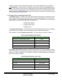
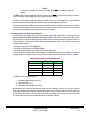
Each exception has its own exception vector offset. The normal offsets are shown in Table 1.
Table 1 Normal Exception Vector Offsets
Name of Exception
Offset
System Reset or Non-Maskable Interrupt
0x100
Machine Check
0x200
Reserved
0x300
Reserved
0x400
External Interrupts
0x500
etc.
etc.
An Exception Vector Table, sometimes just called exception table, is a table of exceptions and their
vectors. For example, if the exception base address = 0x0, then the table is simply the exception vector
offsets (as in the prior paragraph). If the exception base address is 0xFFF0 0000, then the exception
vector table is shown in Table 2.
Table 2 Example Exception Vector Table
Name of Exception
Exception Vector
System Reset or Non-Maskable Interrupt
0xFFF0 0100
Machine Check
0xFFF0 0200
Reserved
0xFFF0 0300
Reserved
0xFFF0 0400
External Interrupts
0xFFF0 0500
etc.
etc.
MPC555 Interrupts
Rev. 0, 26 July 2001
MOTOROLA
2
2.4 Exception Table Relocation
A feature in the MPC555 allows having tighter exception vector offsets for the purpose of saving memory space. This feature, called exception table relocation, “relocates” exception vector offsets by:
• “Relocating” exception vector offsets to be eight bytes apart, instead of 0x100 (256) bytes.
• Allowing additional exception vector base values of: 0x8000 (32 Kbytes)1 and/or bases which move
with the mapping of the internal memory space base, as indicated in the internal memory mapping
register, IMMR[ISB] bit field.
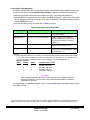
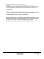
To use the relocation feature, the control bits in Table 3 are used.
Table 3 Relocation Feature Control Bits
Register[Bit]
Bit Name
Description
MSR[IP]
Instruction Prefix
Controls the main base address, either at
0x0 or 0xFFF0 0000.
BBCMCR[ETRE]
Exception Table Relocation Enable
Enables exception vector addresses
relocation. Addresses are separated by 8
bytes instead of 256 bytes. (Requires
MSR[IP] = 1.)
BBCMCR[OERC]1
Other Exception Relocation Enable
Provides an additional offset to the base
address when relocation is used.
IMMR[ISB]
Internal Memory Space Base
Moves exception table base with internal
memory space. (Requires MSR[IP] = 1 and
BBCMCR[ETRE] = 1.)
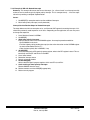
NOTES:
1. On the MPC565 and other future members of the MPC5xx family the OERC field is two bits wide instead
of one and is located in different bit positions of the BBCMCR. Two bits allows for more possible exception locations. See the information below (assumes MSR[IP] = 1 and BBCMCR[ETRE] = 1).
MPC555 MPC565
OERC0
OERC1
Exception Table Location
OERC
0
0
0
0x0 + ISB offset
1
–
–
0x8 000 + ISB offset
–
0
1
0x1 0000 + ISB offset
–
1
0
0x8 0000 + ISB offset
–
1
1
0x3F E000 + ISB offset
CAUTION
When using the relocation feature, a branch absolute (ba) instruction, not just a
branch (b) instruction, must be used at each relocated vector address. Otherwise
exceptions will not work.
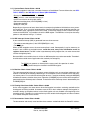
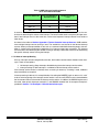
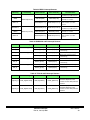
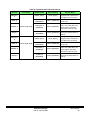
A complete table of all possible exception vectors is listed in Table 4 when the internal memory space
base (ISB) is at 0x0.
1. On
future MPC5xx parts with larger flash blocks, this address will be 0x1 0000 (the second 64 Kbyte flash block). In
addition, these parts can map the exception table to the internal RAM and to the second flash module (if present).
MPC555 Interrupts
Rev. 0, 26 July 2001
MOTOROLA
3
Table 4 Exception Vector Table Alternatives
Exception Vector
MSR[IP] = 0
Exception Vector
MSR[IP] = 1
ETRE = 0
Exception Vector
MSR[IP] = 1
ETRE = 1
OERC = 0
ISB = 000
Exception Vector
MSR[IP] = 1
ETRE = 1
OERC = 1
ISB = 000
Reserved
0x0000 0000
0xFFF0 0000
0x0000 0000
0x0000 8000
System Reset, NMI Interrupt
0x0000 0100
0xFFF0 0100
0x0000 0008
0x0000 00081
Machine Check
0x0000 0200
0xFFF0 0200
0x0000 0010
0x0000 8010
Reserved
0x0000 0300
0xFFF0 0300
0x0000 0018
0x0000 8018
Reserved
0x0000 0400
0xFFF0 0400
0x0000 0020
0x0000 8020
External Interrupt
0x0000 0500
0xFFF0 0500
0x0000 0028
0x0000 8028
Alignment
0x0000 0600
0xFFF0 0600
0x0000 0030
0x0000 8030
Program
0x0000 0700
0xFFF0 0700
0x0000 0038
0x0000 8038
Floating-Point Unavailable
0x0000 0800
0xFFF0 0800
0x0000 0040
0x0000 8040
Decrementer
0x0000 0900
0xFFF0 0900
0x0000 0048
0x0000 8048
Reserved
0x0000 0A00
0xFFF0 0A00
0x0000 0050
0x0000 8050
Name of Exception
Reserved
0x0000 0B00
0xFFF0 0B00
0x0000 0058
0x0000 8058
System Call
0x0000 0C00
0xFFF0 0C00
0x0000 0060
0x0000 8060
Trace
0x0000 0D00
0xFFF0 0D00
0x0000 0068
0x0000 8068
Floating-Point Assist
0x0000 0E00
0xFFF0 0E00
0x0000 0070
0x0000 8070
Reserved
0x0000 0F00
0xFFF0 0F00
0x0000 0078
0x0000 8078
Software Emulation
0x0000 1000
0xFFF0 1000
0x0000 0080
0x0000 8080
Reserved
0x0000 1100
0xFFF0 1100
0x0000 0088
0x0000 8088
Reserved
0x0000 1200
0xFFF0 1200
0x0000 0090
0x0000 8090
Instruction Protection Error
0x0000 1300
0xFFF0 1300
0x0000 0098
0x0000 8098
Data Protection Error
0x0000 1400
0xFFF0 1400
0x0000 00A0
0x0000 80A0
Reserved
0x0000 15000x0000 1BFF
0xFFF0 15000xFFF0 1BFF
0x0000 00A80x0000 00DF
0x0000 80A80x0000 80DF
Data Breakpoint
0x0000 1C00
0xFFF0 1C00
0x0000 00E0
0x0000 80E0
Instruction Breakpoint
0x0000 1D00
0xFFF0 1D00
0x0000 00E8
0x0000 80E8
Maskable External Breakpoint
0x0000 1E00
0xFFF0 1E00
0x0000 00F0
0x0000 80F0
Non-Maskable External
Breakpoint
0x0000 1F00
0xFFF0 1F00
0x0000 00F8
0x0000 80F8
NOTES:
1. System reset/NMI uses 0x0000 0008 instead of 0x0000 8008 in the MPC555 because system reset clears the
OERC bit, although NMI does not. However, later MPC5xx processors such as the MPC565/MPC566 behave
differently — OERC can be set in the Reset Configuration Word or in the BBCMCR.
2.5 Non-Interrupt Exceptions
Although this application note focuses on the setup, control and use of interrupts, it is worthwhile to
briefly describe a number of other common ‘useful’ exceptions available on the PowerPC core.
MPC555 Interrupts
Rev. 0, 26 July 2001
MOTOROLA
4
2.5.1 System Reset: Vector Offset = 0x100
The reset exception is taken from a number of sources as listed below. For more information, see SECTION 7, RESET, in the MPC555 User’s Manual (MPC555UM/AD).
• Reset pins PORESET, HRESET, or SRESET
• IRQ[0], which is a non-maskable interrupt pin
• Clock: loss of lock or on-chip clock switch
• Software watchdog timer (if SYPCR[SWRI] is clear)
• Checkstop condition
• Debug or JTAG port
Depending on the source of reset, three levels of accompanying hardware initializations occur: poweron, hard or soft. Thus, it must be remembered that from executing from vector 0x100 the controller can
be in different states, appropriate care must be used. To check the source of reset, and thus the implications to the MPC555, it is possible to check the RSR register. The RSR bits can only be cleared by
power-on and software writing a “1” to them.
2.5.2 NMI interrupt: Vector Offset = 0x100
A non-maskable interrupt (NMI) is generated from one of two sources:
• The software watchdog timer (if the SYPCR[SWRI] bit is set)
• The IRQ[0] pin
When an NMI exception occurs, the reset vector offset is used. Consequently it may be necessary to
check if it was a NMI that occurred because, unlike the reset, many of the initialization events to
registers do not occur. The NMI is taken asynchronously to the program flow, can never be masked
and has the highest priority.
Because NMI is not maskable, there is risk that an NMI exception may not be recoverable. Therefore it
should not be used for normal applications but used only for emergency.
NOTE
The IRQ[0] can generate an interrupt to the core as well, this operation is undesired. IRQ[0] should always be masked in the SIPEND register.
2.5.3 Machine Check: Vector Offset = 0x200
This separate exception informs of any memory access violations such as non-existent addresses, data
errors or a violation of the memory protection type. The exception can occur for both internal and external memory areas. For a machine check exception to occur, it must be enabled by setting the MSR[ME]
bit before the memory violation takes place. Otherwise (if MSR[ME]=0) no machine check exception is
generated, but the checkstop state is entered. The behavior of the checkstop state is determined by the
PLPRCR[CSR] bit.
2.5.4 Floating-Point Unavailable: Vector Offset = 0x800
As the name suggests, the vector occurs when floating-point instructions are being used without the
floating point unit being enabled. A common cause of this is when software attempts floating-point instructions during an exception routine, but the floating-point unit was disabled at the beginning of the
exception routine. Therefore, it can be used to trap and re-enable the floating-point unit when not done
so in another exception service routine.
2.5.5 Decrementer: Vector Offset = 0x900
The decrementer and closely associated time base counters are defined within the PowerPC architec-
MPC555 Interrupts
Rev. 0, 26 July 2001
MOTOROLA
5
ture as 32-bit decrementing and 64-bit incrementing counters. Both counters are only accessible as
special-purpose register accesses and thus cannot be accessed as memory mapped modules. The major difference between them is that the time base counter causes an interrupt on offset 0x500 while the
decrementer provides a separate exception at 0x900.
The decrementer will cause an exception when it rolls over from all zeros to the LSB being set high
again to begin the counting process. The count value is configurable through the DEC register (SPR22)
but must be set through the use of the special MFSPR and MTSPR (move from and move to special
purpose register) PowerPC instructions. On the MPC555, the decrementer clock is a subdivision of the
processor clock. The clock source is either the system clock (divided by 16) or the oscillator clock input
(divided by 4 or 16) as specified in the time base source bit (TBS) in the system clock control register
(SCCR). The decrementer is enabled by the TBE bit in the time base status and control register (TBSCR).
Although, there are other counters on the MPC555, the decrementer has the advantage of requiring no
decoding for the exception vector and thus is useful for frequently called timer periods, such as an operating system ticks.
2.5.6 Floating-Point Assist: Vector Offset = 0xE00
The purpose of this exception is to provide a mechanism to call a software envelope (routines) to fully
implement the IEEE-754 floating-point specification. The software routine handles a number of extreme
conditions that are rare and expensive to implement in hardware. The software routine will impact the
size and the effect on the average instruction processing speed.
Non-IEEE mode is typically recommended for embedded applications because of faster execution.
However, non-IEEE mode can not cause this execption. See RCPURM/AD Section 3.4.3 for further
information.
2.5.7 Data and Instruction Breakpoints Exception: Vector Offsets = 0x1C00 and 0x1D00
In most cases, these exception vectors are not used. They are reserved for a non-BDM debugger (software monitor) or some user-specific exception. Noirmally the BDM is entered as a result of a data and
instruction breakpoint, then the MPC555 executes instructions received serially via the BDM link. For
more information, see SECTION 21, DEVELOPMENT SUPPORT, in the MPC555 User’s Manual
(MPC555UM/AD).
2.5.8 Maskable and Non-Maskable External Breakpoints Exceptions:
Vector Offsets = 0x1E00 and 0x1F00
As stated in Section 2.5.7 Data and Instruction Breakpoints Exception: Vector Offsets = 0x1C00
and 0x1D00, these exception vectors are not used in most systems. They are reserved for a non-BDM
debugger (software monitor) or some user-specific exception. Typically the BDM is entered as a result
of a maskable and non-maskable external breakpoint, then the MPC555 executes instructions received
serially via the BDM link. For more information, see SECTION 21, DEVELOPMENT SUPPORT, in the
MPC555 User’s Manual (MPC555UM/AD).
2.6 Recoverable Exception [Interrupt]
Sometimes when an exception occurs it may not be possible to recover the machine state. The recoverable interrupt bit in the machine state register, MSR[RI], is a status bit indicating this condition
If a non-maskable exception occurs such as reset, breakpoints or a machine check, software can poll
the MSR[RI] bit to determine if the machine can recover its state. This bit changes state either automatically by hardware or manually under software control. Section 7 Examples of Initialization and In-
MPC555 Interrupts
Rev. 0, 26 July 2001
MOTOROLA
6
terrupt Service Routines will discuss how and when exception routine software must set or reset it.
2.7 EABI Standard
Embedded application binary interface (EABI) is a set of software conventions. They span areas such
as register usage, stack layout and parameter passing. Examples of EABI conventions are dedicating
register r1 the stack pointer, organizing the stack in frames, and assigning certain general-purpose registers (gprs) and floating point registers (fprs) as volatile and nonvolatile among function calls. Compiler
and debug tool vendors have adopted EABI conventions for interoperability. Refer to the Embedded
Application Environments Interface, EABI/D.
MPC555 Interrupts
Rev. 0, 26 July 2001
MOTOROLA
7
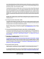
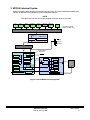
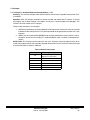
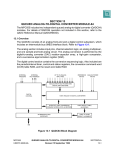
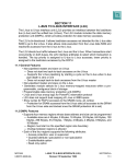
3 MPC555 Interrupt System
Figure 1 contains a block diagram of the overall interrupt system. This system will be discussed by starting with the MPC555 core and working out to the peripheral devices.
NOTE
This application note will assume the exception relocation feature is not used.
TPU3
A
TPU3
B
[16]
MIOS1
[16]
QADC64
A
[20]
QADC64
B
[4]
TOUCAN
A
TOUCAN
B
[19]
[19]
[4]
QSMCM
[15]
Possible Interrupt
flags for module in [ ]
IMB3 BUS
8-32
UIPEND
UIMB Interface
UMCR[ IRQMUX ]
IRQ[0:7]
external
interrupts
8
U BUS
8
8
USIU
Timebase
SIPEND
Real-time clock
PIT
IRQOUT
SIEL
[2]
[2]
USIU Interrupt
Controller
IRQ[0]
IREQ
MSR[EE]
Vector Table
SIMASK
PowerPC
Core
n+0x100
&
PLL
SW Watchdog
Address
SIVEC
n+0x500
Exception
Vector
Table
at X0 or
0XFFF 0000
n+0x900
NMI control
SSR1
Decrementer
BDM Debug
SSR0
Instruction Buffer
Instruction Code
Figure 1 Overall MPC555 Interrupt System
MPC555 Interrupts
Rev. 0, 26 July 2001
MOTOROLA
8
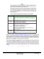
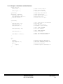
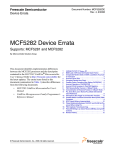
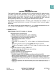
3.1 PowerPC Core Interrupt
The PowerPC core has only a single interrupt input, which is from the interrupt controller. See Figure
2. This interrupt is enabled by the external interrupt enable (EE) bit in the machine state register (MSR).
Besides enabling interrupt exceptions, this bit also enables the decrementer exception.
SPR80 SPR81
EIE
PowerPC
Core
SPR82
EID
NRI
EE
RI
Vector Table
MSR
IREQ
n+0x100
Address
&
RESET
or
NMI
n+0x500
Decrementer
n+0x900
SSR1
(saves MSR value
before exception)
Exception
Vector
Table
at 0X0 or
0XFFF0000
(internal
or external
memory)
SSR0
(saves address of
stopped instruction)
Instruction Buffer
Instruction Code
NOTE: The MSR[EE] bit must be set in order to allow the PowerPC processor to recognize any
interrupts.
Figure 2 PowerPC Core Interrupt
(without Vector Table Relocation)
Before recognizing the interrupt exception, all instructions being executed are completed. Once the core
recognizes any exception, hardware automatically performs a machine state saving context switch as
shown in Table 5.
MPC555 Interrupts
Rev. 0, 26 July 2001
MOTOROLA
9
NOTE
Only negate interrupt sources while MSR[EE] = 0. Software should disable interrupts in the CPU core (by clearing this bit) prior to masking or disabling any interrupt which might be currently pending at the CPU core.
After disabling an interrupt, sufficient time should be allowed for the negated signal
to propagate to the CPU core, prior to re-enabling interrupts. The worst case time
is an interrupt from an IMB3 module, which would be six clocks if the IMB3 is in full
speed mode (UMCR[HSPEED] = 0) or 12 clocks if the IMB3 is in half-speed mode
(UMCR[HSPEED] = 1).
Table 5 Exception Context Switch Automatically Done By Hardware
Register/Pointer
Action
SRR0
Gets loaded with an instruction address depending on the exception. For
interrupts and most other exceptions, it is address of the next instruction, (i.e.,
the instruction that would have been executed if the interrupt exception did not
occur).
(Previous SRR0 contents are overwritten.)
SRR1
SRR1[0:15] gets loaded with information depending on exception type.
SRR1[16:31] gets loaded with MSR[16:31].
(Previous SRR1 contents are overwritten.)
MSR
Recoverable exception status bit is cleared (RI=0)
Privilege level is set to supervisor and user (PR=0)
Little-endian mode is disabled (LE=0)
Maskable exceptions are disabled, which are:
– External interrupt exceptions (EE=0)
– Floating-point unit and floating point exceptions (FP=FE0=FE1=0)
– Single-step trace exceptions (SE=0)
– Branch trace (BE=0)
Instruction
Pointer
Branches to start execution at the interrupt exception “vector”. By default, this
is location 0x500 (assuming the MSR.IP bit = 0 and exception relocation is not
enabled).
As mentioned in Section 2.6 Recoverable Exception [Interrupt], the purpose of the MSR[RI] bit is to
indicate non-recoverable situations. For example: an interrupt exception occurs, causing hardware to
back up the next instruction and MSR bits to SRR0:1. If SRR0:1 are not backed up somewhere and
another exception occurs, their contents are lost. Hence the original state and instruction address prior
to the interrupt is lost. As will be shown later, interrupt exception software typically will need to back up
SRR0:1 and then set MSR[RI] = 1 to indicate the state is recoverable.
The EIE, EID, and NRI special purpose registers have the sole purpose of providing a mechanism to
quickly modify the MSR[RI] and MSR[EE] bits. Any writes to these registers cause these bits to be set
or cleared as in the table below. Writing to these registers can only be done in assembler because they
are special purpose registers, not memory-mapped. Hence they are not accessible from the c language.
To access them we must use the assembly language instruction “mtspr”. For example see below and
Table 6.
mtspr
EID, r0
; Set RI bit = 1 and EE bit = 0 in MSR
MPC555 Interrupts
Rev. 0, 26 July 2001
MOTOROLA
10
Table 6 Manipulating EE and RI Bits
SPR
Mnemonic
MSR[EE]
MSR[RI]
80
EIE
1
1
81
EID
0
1
82
NRI
0
0
At the end of the interrupt routine, executing a return from interrupt (rfi) instruction restores the context
by hardware. This causes the action shown in Table 7.
Table 7 Return From Interrupt Context Switch
Register/Pointer
MSR
Instruction
Pointer
Action
MSR[16:31] gets re-loaded from SRR1 (enabling external interrupts, other
maskable exceptions, etc. again.)
Gets re-loaded from SRR0, which resumes program execution after the last
executed instruction before the interrupt was recognized.
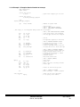
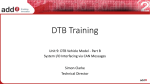
3.2 USIU Interrupt Controller
The main interrupt controller is in the USIU module. However, there are interrupt controller functions in
other areas, such as the level mapping of peripherals in the UIMB module (see Section 3.6 Interrupt
Sources: UIMB Peripherals).
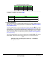
The USIU interrupt controller has 16 inputs: eight external interrupt request pins (IRQ[0:7]) and eight
internal interrupt “levels”. As mentioned in Section 2.2 Interrupt Sources and Levels, levels are a
mapping mechanism for interrupt sources and imply a priority. Interrupt sources inside the USIU (time
base, real-time clock, PIT and PLL change of lock detector) are assigned a level 0:7. Interrupt sources
from peripherals on the IMB3 bus can have levels 0:31. However, these IMB3 bus peripherals with levels 7:31 are all mapped to level 7 of the USIU interrupt controller (see Section 3.4 Interrupt Sources:
USIU Internal Devices).
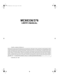
The 16 USIU interrupt controller inputs (8 pins and 8 levels) are fed into the SIPEND (USIU interrupt
pending register). Software can read this register to see which of the 16 interrupts are pending.
NOTE
The MPC565 and other future MPC5xx family members have an enhanced interrupt controller that is backwards compatible to the MPC555. The new features
must explicitly be enabled.
MPC555 Interrupts
Rev. 0, 26 July 2001
MOTOROLA
11
From Peripherals on IMB3 bus
L0 L1 L2 L3 L4 L5 L6
Interrupt levels 7or 7-31
UIPEND
IRQ[0:7]
external
interrupts
USIU Module
Interrupts can
be at any level
USIU module
Timebase
SIEL
Real-time clock
ED0 – ED1 – ED2 –
PIT
ED3
– ED4 – ED5
– ED6 – ED7 –
Reserved bits 16-31
(External interrupts can be
falling edge or level 0
active)
PLL
I0
I0
L0
L0
I1
I1
L1
L1
I2
I2
L2
I3
L2
L3
I3
I4
L3
I4
L4
I5
L4
I5
L5
L5
I6 L6
I6 L6
I7
I7
L7
L7
Reserved bits 16-31
Reserved bits 16-31
SIPEND
SIMASK
(Enables interrupts
through to IREQ)
Priority
Arbiter
+
8
IREQ
- to PowerPC core
8-bit code for all 16 sources (others reserved)
SIVEC
Figure 3 USIU Interrupt Structure
The SIMASK (USIU mask register) contains corresponding mask bits for each SIPEND interrupt bit. In
order for interrupts to be fed into the CPU core, the corresponding mask bit must be set. At RESET, the
SIMASK register is set to all 0’s, disabling all interrupt sources.
SIMASK[IRM0] bit is a special case. This is the mask bit for the IRQ[0] input pin, which is a nonmaskable interrupt. Setting this bit to 0 has no effect.
After the SIPEND and SIMASK registers, there is a priority arbiter and encoder. This gives a number
called interrupt code to the highest priority unmasked interrupt. If two or more unmasked interrupt requests occur at the same time, the one with the lowest numbered interrupt code will have priority.
The interrupt code is located in a field of the SIVEC (USIU interrupt vector register). during the interrupt
service routine, the interrupt code will be used as in index into a branch table for branching to the appropriate interrupt source’s service routine. This is why each interrupt code is separated by four bytes,
the width of one instruction. See Table 8.
MPC555 Interrupts
Rev. 0, 26 July 2001
MOTOROLA
12
NOTE
Other lower priority or masked interrupt requests can be examined at any time by
reading the SIPEND register. If no unmasked interrupt request is pending, the Interrupt Code has a default value of 0x3C.
Table 8 Interrupt Priority and Codes
Priority
Interrupt Source
Interrupt Code
(Binary)
Interrupt Code
(Hex)
0 (highest)
IRQ[0] Input Pin1
00000000
0x0
1
Level 0
00000100
0x4
2
IRQ[1] Input Pin
00001000
0x8
3
Level 1
00001100
0xC
4
IRQ[2] Input Pin
00010000
0x10
5
Level 2
00010100
0x14
6
IRQ[3] Input Pin
00011000
0x18
7
Level 3
00011100
0x1C
8
IRQ[4] Input Pin
00100000
0x20
9
Level 4
00100100
0x24
10
IRQ[5] Input Pin
00101000
0x28
11
Level 5
00101100
0x2C
12
IRQ[6] Input Pin
00110000
0x30
13
Level 6
00110100
0x34
14
IRQ[7] Input Pin
00111000
0x38
15
Level 7
00111100
0x3C
(Default value)
16-31
Reserved
—
—
NOTES:
1. IRQ[0] Input Pin is a special case. See 3.3 Interrupt Sources: External IRQ Pins.
3.3 Interrupt Sources: External IRQ Pins
As shown in the interrupt code table previously, the eight interrupt pins have unique interrupt codes. The
system designer must ensure the application’s higher priority external interrupts have lower number interrupts. Each external interrupt pin has a mask bit in the SIMASK register to enable it. IRQ[0:7] have
six priorities and interrupt code. The hardware design must connect higher priority interrup signals to
the lower number of interrupt pins, such as IRQ[1] or IRQ[2].
IRQ[0] is a special case. This is non-maskable and causes a NMI exception. It uses the reset exception
vector offset, but does not cause an actual reset. Hence the exception vector will be 0x100 instead
of 0x500. If the RESET exception routine needs to determine the cause of the reset, then the reset status register (RSR) and SIPEND[IRQ0] bit are examined.
CAUTION
Because IRQ[0] can cause a nonmaskable exception, it can cause an irrecoverable condition. Therefore, it should not be used for a normal application input.
MPC555 Interrupts
Rev. 0, 26 July 2001
MOTOROLA
13
NOTE
A software watchdog can also cause a NMI reset. IRQ[0] is ALWAYS edge triggered.
The SIEL (USIU interrupt edge level register) contains bits for IRQ[0:7] input pins to specify if the interrupt is caused by a falling edge (ED=1) or simply a low level (ED=0).
Typically a falling edge interrupt input (ED=1) is used. In this case, the appropriate bit in the SIPEND
must be cleared in the interrupt service routine when a falling edge interrupt occurs.
Low level interrupt inputs (ED=0) are used for wired-OR situation of multiple sources on one line. When
an interrupt of this type occurs, the interrupt service routine must ensure the interrupt line is returned to
the inactive high state before exiting the interrupt service routine.
3.4 Interrupt Sources: USIU Internal Devices
All interrupt sources except external IRQ pins must be given level assignments in some register (see
Section Appendix A Table of Potential Interrupt Sources). These level assignments map the interrupt source to an input of the USIU interrupt controller. When the interrupt source attempts to initiate an
interrupt request, its level to the USIU interrupt controller becomes active. The interrupt controller will
recognize the interrupt if:
• Interrupts are enabled in the MSR[EE] bit
• The level is not blocked in the SIMASK register
• The level is not competing with a higher priority interrupt request.
Levels in the USIU interrupt sources are assigned in an 8-bit field with the format in Table 9. A common
mistake made is to attempt to use a binary value of the level instead of the pattern shown in Table 9.
Table 9 IUSIU Interrupt Level Assignments
Level Assignment
Binary Value
Hex Value
0
10000000
0x80
1
01000000
0x40
2
00100000
0x20
—
—
—
7
00000001
0x01
The USIU has four interrupt sources:
1.
2.
3.
4.
Programmable interrupt timer (PIT)
Time base (TB)
Real-time clock (RTC)
Phase lock loop change of lock (PLL)
Some sources can cause an interrupt from more than one condition, but each has only one interrupt
level. For example, the time base has one level but can cause an interrupt when it matches either one
of two time base reference registers TBREFA or TBREFB. Each time base reference has its own interrupt enable bit and each has its own status bit. If both are enabled, the time base interrupt service routine must check the status bits to determine which caused the interrupt.
MPC555 Interrupts
Rev. 0, 26 July 2001
MOTOROLA
14
NOTE
Some interrupt sources have a freeze control bit. Generally this allows timers to
keep incrementing or decrementing if the FREEZE debug signal is asserted. The
FREEZE signal allows users to stop various clocks to aid debugging. It is active
when in debug mode, (i.e., when instructions are executed from the debug port) instead of from memory.
EXAMPLE
PIT Interrupt. The steps below will generate an interrupt request at the interrupt
controller when the PIT crosses zero. We will not enable interrupts to the core in
this example. If you have an evaluation board with visibility into registers and bit
fields, this would be a simple exercise to start understanding and experimenting
with interrupts. It assumes the default clock to the PIT is used and is enabled.
1. Set PITC[PITC]=0x1000 for a modulus count (gets loaded when PITR decrements passed 0)
2. Make sure PISCR[PITF]=0 to keep PIT the clock running during while the debug signal
FREEZE is asserted. (0 is the default value from reset.)
3. Set PISCR[PIRQ] = 0x40 to set the PIT’s interrupt level to level 0
4. Enable level 0 by setting SIMASK[LVLM0]=1
5. Set PISCR[PTE]=1 to enable the PIT clock to decrement.
6. Enable PIT interrupt by setting PISCR[PIE] = 1
Now watch the PIT decrement. When it reaches 0, the PIT status bit PISCR[PS] will set, which sets the
SIPEND bit for level 0 and the interrupt code in SIVEC to level 0. The PISCR[PS] will stay set until a “1”
is written to that bit, which means SIPEND will stay active for level 0 until, (e.g., a “1” is written to that
bit). The processor does not take the interrupt exception because the MSR[EE] bit has not been set.
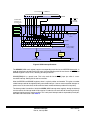
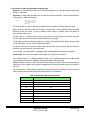
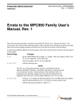
3.5 UIMB Module
All interrupts from peripherals on the IMB are passed into the UIMB module. The UIMB module has an
interrupt controller function of reducing up to 32 possible interrupt levels to 8 levels. These 8 levels go
to the SIPEND register in the USIU Interupt Controller. To achieve this reduction, IMB peripheral interrupt levels 7:31 all get mapped to level 7 as shown in Figure 4.
MPC555 Interrupts
Rev. 0, 26 July 2001
MOTOROLA
15
Registers used TPU3_A
to enable ints
and read the
status. Level
setting regs.
are not
CIER
shown
CISR
TPU3_B
MIOS1ER0 or 1
CIER
CISR
[16]
QADC64_A
MIOS1
MIOS1SR0 or 1
[16]
QADC64_B
TOUCAN_A
TOUCAN_B
TCNMCR
TCNMCR
QACR1
QACR1
CANCTRL0
CANCTRL0
QACR2
QACR2
IMASK
IMASK
QASR0
QASR0
[20]
IFLAG ESTAT
[4]
[4]
IFLAG
[19]
QSMCM
SPI
SPCR2 SPCR3
ESTAT
SCI
SCCxR1
SPSR
SCxSR
[15]
[19]
Peripheral
Interrupts
can be set to
any level
No. of
interrupt
sources in []
Levels 0 -7
Levels 16-23
Levels 8-15
Levels 24-31
IMB3 BUS
Interrupt levels are
time-multiplexed
onto bus
UIMB module
UMCR enables the
use of levels 8-31
IRQMUX0 IRQMUX1
UIPEND
{
{
L0 L1 L2 L3 L4 L5 L6 L7 Interrupt levels 8 to 31 are optionally enabled
UMCR
SIPEND Levels 0:6
UIPEND has 32 IMB3
interrupt levels that map
to SIPEND with the
external interrupts.
SIPEND Level 7
NOTE: UIPEND levels 0:6 map directly to SIPEND levels 0:6. UIPEND 7:31 map to SIPEND level 7.
Figure 4 Peripherals and the UIMB Interrupt Structure
Table 10 summarizes the mapping.
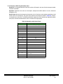
Table 10 UIMB Interrupt Level Mapping
Interrupt Level
Interrupt Level from
from IMB Peripheral to UIMB Module to USIU
UIMB Module
Interrupt Controller
Relative Overhead to Identify
Interrupt Source
0
0
Fast – use SIVEC only
1
1
Fast – use SIVEC only
2
2
Fast – use SIVEC only
3
3
Fast – use SIVEC only
4
4
Fast – use SIVEC only
5
5
Fast – use SIVEC only
6
6
Fast – use SIVEC only
7:31
7
Normal – use SIVEC and UIPEND
MPC555 Interrupts
Rev. 0, 26 July 2001
MOTOROLA
16
IMB peripherals needing faster interrupt response should use levels 0 through 6 since only SIVEC register is necessary to identify the interrupt source, unless more than one source shares the same level.
IMB interrupt levels 7:31 are all “shared” on level 7 input to the USIU interrupt controller. Hence additional decoding of a source is normally required, which would use the UIPEND register.
The UIPEND register reflects the status of the 32 IMB interrupt levels. It is a read-only register.
The levels coming into the UIMB from the UIMB peripherals use multiplexing for efficiency. Levels in
these peripherals are represented by five bits [0:31]. The UIMB does not read all levels at once. It time
multiplexes a three-bit level value [0:7] with four time slots as shown in Table 11.
Table 11 UIMB Time Multiplexing
Multiplexed 3-bit
Level
2-bit Time Slot
Generated IRQ Level
0…7
0
0…7
0…7
1
8 … 15
0…7
2
16 … 23
0…7
3
24 … 31
The UMCR register contains the control bits called IRQMUX to enable mapping of 32 possible interrupt
requests from the UIPEND to the eight interrupt inputs of the USIU interrupt controller.
3.6 Interrupt Sources: UIMB Peripherals
The UIMB interrupt sources include the following peripheral modules on the UIMB bus: two TouCAN
modules, two QADC modules, two TPU modules, one MIOS1 module, and one QSMCM module. Each
module has numerous conditions that can cause an interrupt, but have only one or two interrupt levels.
For example, any of a TPU’s 16 channels can be set up to cause an interrupt, but there is only one interrupt line (level) leaving the module. (See Table 25.) The interrupt service routine must determine not
only that the TPU caused the interrupt, but which channel caused it as well.
Levels are assigned in the module’s level register. Although there are 32 possible levels, they are multiplexed on to eight inputs to the UIMB. For historical reasons, peripherals designate levels in two possible methods:
1. A single 5 bit “level” field, for levels 0 – 31 as follows. This applies to interrupt sources in USIU,
QADC, and QSMCM modules.
Table 12 UIMB Interrupt Level Assigment
for 5-bit Level Field
5-bit Level Field Value
Level
00000
0
00001
1
00010
2
—
—
11111
31
2. A 3-bit “level” field for levels 0:7 and a 2 bit “time multiplex” or “byte select” field for multiplexing
levels to a time slot. This applies to interrupt sources in TPU3 and MIOS1 modules.
MPC555 Interrupts
Rev. 0, 26 July 2001
MOTOROLA
17
Table 13 UMB Interrupt Level Assignment
for 3- and 2-bit Level FIelds
3-bit Level Field Value
2-bit Time Multiplex or
Byte Select Field
Peripheral Interrupt
Level
000 to 111
00
0 to 7
000 to 111
01
8 to 15
000 to 111
10
16 to 23
000 to 111
11
24 to 31
A common rule is to have each module use a different interrupt level to minimize interrupt service routine time in determining the source of the interrupt. The lower number levels have priority of higher numbers if two interrupts occur at the same time, so the more important interrupt sources must reside at
lower levels.
As shown in the tables of Section Appendix A Table of Potential Interrupt Sources, UIMB modules
have multiple interrupt sources sharing a level. The enable bits must be set for the desired interrupt
sources. When an interrupt condition is met, such as a communication buffer becoming empty, that condition is “anded” with its enable bit to determine if an interrupt request gets passed on. The interrupt
service routine, once identifying the module causing an interrupt, checks the status bits for determining
the specific interrupt source causing the interrupt.
3.7 A Note on Interrupt Nesting
Once an interrupt has been recognized by the core, the hardware context switch disables further interrupts. There are two options:
1. No interrupt nesting: Keep interrupts disabled during the entire interrupt service routine.
2. Interrupt nesting: Enable interrupts in a window inside the interrupt service routine.
If the interrupt service routine is relatively short, no nesting is necessary. If nesting is used, additional
steps (overhead) are required.
If interrupt nesting is desired, it is accomplished by first setting the MSR[EE] again as soon as it is “safe”
to do so at the beginning of the interrupt service routine. Later the same EE bit must be cleared before
the final context switch at the end of the interrupt service routine. In addition, the SIMASK register must
be saved, lower priority interrupts masked in it, and SIMASK restored later. A conceptual example is
provided in Section 7.3.6 Example 6: ISR with Nested Interrupts.
MPC555 Interrupts
Rev. 0, 26 July 2001
MOTOROLA
18
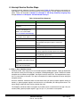
4 Initialization Steps
Each interrupt source must be initialized before all interrupts can be enabled in the machine state register, EE bit. Initialization consists of four steps: module specific initialization, level assignment, enabling
the interrupt source, and setting the interrupt mask in the SIU interrupt controller.
The initialization steps below are broken out for illustrating completeness, and do not illustrate the most
efficient programming methods.
4.1 Step 1: Module Specific Initialization
Each interrupt source will need to have its own general initialization of its module. Complete module
initialization is outside the scope of this application note. Examples of some module specific initializations are:
• Interrupt Pins: specify edge or level detection
• Timers: specify clock input selection, clock prescaler value, pre-loading value
• Serial I/O: specify baud rate, queue management parameters
• QADC: specify queue management parameters
• TPU, MIOS: specify function assignment, function specific parameters
4.2 Step 2: Level Assignment
The system designer must make careful assignment of levels to each interrupt source. Key points to
remember as discussed in the Section 3.2 USIU Interrupt Controller and Section 3.5 UIMB Module
sections are summarized here:
• Lower level numbers have higher priority
• External interrupt pins do not have level assignments but have a fixed priority
• To reduce latency, each interrupt source should be mapped to its own level if possible
• When UIMB peripherals have levels over 7, the UMCR[IRQMUX] field must be set to enable
appropriate multiplexing.
The registers used for level assignments for each interrupt source are listed in Section Appendix A
Table of Potential Interrupt Sources. Remember, level registers use either a single 5-bit field or 3-bit
and 2-bit fields to assign levels as discussed in the section Section 3.6 Interrupt Sources: UIMB Peripherals.
4.3 Step 3: Enable Interrupt
Each interrupt source other than IRQ pins must be enabled. The enable control bit for the sources are
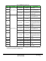
listed in Section Appendix A Table of Potential Interrupt Sources.
4.4 Step 4: Set Appropriate Mask Bits in SIMASK
All appropriate USIU interrupt controller levels 0:8 must have their mask bits set (enabled) in the SIMASK register.
4.5 Final Step: Setting MSR[EE] and MSR[RI] Bits
After all the interrupt sources have been initialized to the previous steps, the enable external interrupts
[EE] bit must be set for interrupts to be recognized and recoverable interrupt [RI] set to tell exceptions
the state is recoverable. This is easily done by using the EIE special purpose register as mentioned in
the prior Section 3.1 PowerPC Core Interrupt section. Writing any value to the EIE register sets both
the MSR[EE] and MSR[RI] bits. Writing is accomplished by using the mstpr instruction.
Example: mtspr EIE, r0
MPC555 Interrupts
Rev. 0, 26 July 2001
MOTOROLA
19
5 Determining Which Registers to Save and Where to Save Them
Before writing software for the interrupt service routine (ISR), you must determine how much “context”
to save and where to save it. In general, any registers that could be modified during in the ISR should
be saved on the stack.
How much is saved can vary dramatically among applications. For example, if all software executed
during the interrupt exception is written in assembler, then only those few registers used can be easily
identified and saved on the stack.
However, if the ISR calls a C routine, then the compiler could use the scratch registers (called volatile
registers) as defined in the EABI. Therefore, all volatile registers must be saved because it cannot be
predict which registers the compiler will use. Other registers that a compiler might use will need to be
saved also, such as XER (which has the carry), CR (for compares) and CTR (for counter/branch uses).
Some applications may want to even save timer values.
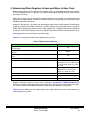
Table 14 is an example checklist to help determine what to save.
Table 14 Register Save Checklist
ISR Requirement
Comply with stack conventions [EABI] used by compiler and debug tools
(recommended)
Register(s) to be Saved
SP
Additional exceptions, including debug breakpoints), are allowed during the
exception.
SRR0:1
Use LR, (e.g., for calling an assembler or C routine handler) for an interrupt
source
LR
Call assembler routines only (no floating point in ISR)
gprs used in routines
Call C routine (no floating point in ISR)
Per EABI, save all volatile gprs (gpr0,
gpr3:12) plus any other registers that
a C routine could change (e.g., XER,
CR, CTR)
Complete context switch, such as with an RTOS (no floating point)
All gprs (gpr0:31) plus any other
registers that a C routine could
change (e.g., XER, CR, CTR)
Use floating point registers in assembly routines only
Use floating point in C routine
fprs used in routine
All volatile fprs (fpr0:13)
Use floating point with complete context switch, as with an RTOS
All fprs (fprs 0:31)
Registers should be saved in a stack frame, as defined in the Section 2.7 EABI Standard. Stack
frames are created by decrementing the stack pointer by a size that can be used to store all the registers. Stack frames must be modulo eight bytes, so four bytes of padding may be required.
Table 15 lists the EABI stack frame organization and a sample ISR stack frame. In this example, the
volatile registers are saved.
MPC555 Interrupts
Rev. 0, 26 July 2001
MOTOROLA
20
Table 15 EABI Stack Frame Organization
EABI Stack Frame
Example ISR Stack Frame
Prior back chain
Prior SP
New
fpr save area
Stack
gpr save area
Volatile gprs (gpr0, gpr3:12)
Frame
CR save area
CR
Local variables
CR, XER, LR, padding (if padding is required so stack frame is modulo 8 bytes)
LR save area
(Reserved for function called by ISR)
Back chain
SP
CAUTION
Special care should be used in saving the LR. For normal application functions, the
LR is stored in the current stack frame and a new stack frame is created. However,
since an exception routine function can occur anytime, the normal LR save area
may already be in use. One solution is for exception routines to save the LR elsewhere on the stack, such as in the local variables area.
MPC555 Interrupts
Rev. 0, 26 July 2001
MOTOROLA
21
6 Interrupt Service Routine Steps
A general interrupt sequence of events is summarized in Table 16. When software saves special-purpose registers, a gpr must be saved also because it must be used as a scratch register for transfer purposes. These are illustrated in Section 7.3.2 Example 2: ISR Using Assembly Language Only
through Section 7.3.6 Example 6: ISR with Nested Interrupts.
Table 16 Interrupt Event Sequence
System Behavior
Software Steps
Exception occurs
Currently executing instructions are
completed
The CPU saves the address of next
instruction and MSR[16:31] in
SRR0:1, then modifies MSR
(see 3.1 PowerPC Core Interrupt).
The instruction pointer branches to
the exception vector address.
1. Save “Machine Context” of SRR0:1.
2. Set MSR[RI] to indicate the state is now recoverable.
Other maskable interrupts/exceptions could now be
enabled.
3. Save other appropriate context (registers).
4. Determine interrupt source.
5. Branch to interrupt handler and execute it. If
necessary, negate the interrupt request in the handler.
6. Restore contexts, disabling maskable exceptions &
clearing MSR[RI] appropriately.
7. Return to program by executing “rfi” instruction.
The CPU restores return address,
original MSR, and enables interrupts
again.
Program execution resumes in the
routine that was interrupted.
6.1 Step 1: Save “Machine Context”
“Machine context” here means the save and restore registers, SRR0 and SRR1. These get loaded with
the machine state by the CPU when any exception (including debugger) is taken. Therefore if another
exception occurs without saving SRR0:1, the original machine state is lost. The expected normal practice is to save these on the stack. This step is not required if no other exceptions will occur during the
exception routine.
Since the PowerPC architecture does not allow direct writing of special-purpose registers directly to
memory, a general-purpose register must be used as an intermediary for storing these values. This
means the gpr used itself must also be saved on the stack.
The PowerPC architecture does not support any hardware stack, so software will manage it. By convention (EABI), general-purpose register 1 (gpr1, or just “r1”) is used for a stack pointer.
MPC555 Interrupts
Rev. 0, 26 July 2001
MOTOROLA
22
The following illustrates saving the machine context for a stack frame of size 80 bytes. Register r3 is
saved so it can be used as a scratch register. We will assume the assembler has the symbol “sp” defined as “r1” for legibility. This illustration assumes what to save and where to save it on the stack frame
has been defined. Complete examples are provided Section 7 Examples of Initialization and Interrupt Service Routines.
stwu
stw
mfsrr0
stw
mfsrr1
stw
sp,
r3,
r3
r3,
r3
r3,
-80 (sp); Create stack frame and store back chain
36 (sp); Save a working register in stack frame for use as a scratch register
; Copy SRR0 to r3
12 (sp); Save SRR0 value on stack
; Copy SRR1 to r3
16 (sp); Save SRR1 value on stack
6.2 Step 2: Set MSR[RI]
As described earlier, the recoverable interrupt bit in the machine state register indicates the machine
state can be recovered if a subsequent exception occurs. If SRR0 and SRR1 have been saved as in
step 1, software should set this bit to indicate to any other exception routine this backed up condition,
(i.e., recoverable state). This bit is most easily set writing any gpr to the special purpose register EID.
Example:
mtspr
EID, r3; Set MSR[RI] to indicate recoverable condition
Any asynchronous exception (such as reset) could check the RI bit of the MSR now saved in the SRR1.
If the RI bit is 0, then the software will know the exception is non-recoverable. This can only happen if
there is a reset or some major problem with either the software or the whole system.
Debugging Comments: Since debugging is also done by exception, if a breakpoint is taken while RI =
0, then machine state is presumed lost. In general, breakpoints are recognized in the CPU only when
the RI bit is set, which guarantees that the machine restarts after a breakpoint.2 In this mode, breakpoints are considered “masked”. Internal breakpoints also have a non-masked mode where they are
recognized at any time. If one occurs while RI=0, then the user can debug the exception routine, however at the end of the exception there is no way to return to the main program.
6.3 Step 3: Save Other Appropriate Context (Registers)
Based on what else the user has determined to be saved on the stack, code will save appropriate registers. Any gpr registers can be saved with one instruction. For example:
stw
r4, 40 (sp)
; Store gpr4 on stack
Special-purpose registers take two instructions, like SRR0 and SRR1. Example:
mfxer
stw
r3
r3, 20 (sp)
; Copy special purpose register XER to gpr3
; Save XER value to stack
To optimize saving and later restoring context, the load / store multiple word (lmw / stmw) or load / store
string word immediate (lswi / stswi) instructions can be used. Using the multiple word or string word immediate instructions also shorten execution time. (The lmw / stmw instructions start saving registers at
r31, so this would be if all the gprs would be saved.)
If interrupt nesting is to be allowed, then the SIMASK register may also need to be saved and MSR[EE]
bit set. An example later illustrates how this is done.
6.4 Step 4: Determine Interrupt Source
To determine the interrupt source, the following sequence can be taken:
2.
MPC555 Users Manual, (MPC555UM/AD), 21.3 Watchpoints and Breakpoints Support, Rev. 1 June 2000
MPC555 Interrupts
Rev. 0, 26 July 2001
MOTOROLA
23
1. Check the INTERRUPT CODE field in the USIU interrupt controller’s SIVEC register, see Table
8. This value will be an index to a jump table.
2. If the interrupt source is level 7 and the application has interrupt sources mapped to level 7 and
beyond, then check the UIPEND register for levels beyond level 7. The CNTLZW instruction
can be used to count the number of zeros in the UIPEND from bit 0 until the first “1”. The number
can then be used as an index to a second jump table.
3. If more than one interrupt source shares the same level, then check both sources.
4. If necessary, check for which of several possible conditions within a module caused the interrupt. For example, which of 16 TPU channels caused the TPU interrupt.
The SIVEC[INTERRUPT CODE] can efficiently be used as an index into a jump table. A jump table will
contain pointers to the various interrupt handlers for each source. By adding the index to the address
of the start of the table, the address of the source’s handler routine can be loaded into a register that
can be used for branching, like the LR.
6.5 Step 5: Branch to Interrupt Handler and Execute It
“Interrupt handler” here is defined as interrupt service routine code specific to a module.
Once the address of the interrupt source’s handler routine is loaded in a register, then we can branch
to it. The architecture allows branching from the CTR or LR registers, so the address must be loaded
into one of them.
IMPORTANT
Save the address of the next instruction to the LR by using the “l” option in the
branch instruction. For example:
blrl
; Jump to interrupt handler routine and save the next instructions address in LR
IMPORTANT
Depending on the interrupt source, it may be necessary to negate the interrupt condition so it will not cause further interrupts.
If the interrupt handler routine is written in C, the program will return to the next instruction after the
above “blrl” at the end of the routine. If the routine is written in assembler, then the last instruction needs
to be:
blr
; Return from interrupt handler routine to restore contexts.
6.6 Step 6: Restore Contexts
Restoring contexts includes anything saved on the stack in steps 1 and 3, such as SRR0:1, gprs, etc.
These are combined in one step here. Sample lines to restore some registers are:
lwz
lwz
mtxer
r4, 40 (sp)
r3, 20 (sp)
r3
; Restore gpr4 from stack
; Restore XER value from stack
; Copy XER value to XER register
Care must be taken to clear the MSR[RI] bit before restoring SRR0:1 to indicate an exception during
restoring these registers can result in an unrecoverable condition.
As mentioned before, the load multiple word (lmw) or load string word immediate (lswi) instructions can
shorten restoring contexts.
6.7 Step 7: Return to Program
A single instruction, return from interrupt, will exit the interrupt exception routine. This instruction restores the MSR from SRR1, which can re-enable exceptions such as external interrupts, the (MSR[EE]
bit), floating-point unit (MSR[FP] bit) and others in the MSR. The instruction pointer gets loaded with the
address in SRR0 and processing branches to that location. Example:
rfi
MPC555 Interrupts
Rev. 0, 26 July 2001
MOTOROLA
24
7 Examples of Initialization and Interrupt Service Routines
The following examples illustrate different techniques of handling interrupt exceptions. They have been
tested on a MPC555 evaluation board with a debugger. Code was compiled using the Diab Compiler
Version 4.3G. Examples 2 through 5 were tested using a standard personal computer terminal program
with settings of 9600 baud, 8 data bits, no parity, 2 stop bits and no flow control. If running these programs, a standard serial cable is requried, and possibly a null modem adapter.
Initialization comments: Interrupt initialization, such is in the “initPIT” function in the first example or
“initSci” function in other examples, is written for illustration, not to optimize code.
Processor initialization, done in the function “init555”, is minimal for these examples. Common items
to initialize are:
1.
2.
3.
4.
5.
6.
SYPCR: disable watchdog timer
SIUMCR: disable data show cycles
PLPRCR: increase clock frequency using MF bit field and optionally wait for PLL to lock
UMCR: set UIMB bus to full speed using HSPEED bit
SPR560 (BBCMCR): enable burst buffer
SPR158 (ICTRL): Increase processing speed by taking processor out of serialized mode
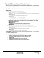
7.1 Example Interrupt Service Routines (ISRs):
1.
2.
3.
4.
5.
6.
Absolute minimum interrupt routine – PIT
ISR using assembly language only
ISR using assembly and C
ISR using C only – one interrupt source
ISR using C only – general case
ISR with nested interrupt capability (conceptual example)
7.2 Files Used for Examples
The files in Table 17 are used in the examples, except where noted.
Table 17 Example Files
File Name
Description
main.c
Varies for each example, but always initializes the CPU and interrupt
device and waits in a loop
exceptions.s
Interrupt Service Routine which calls an interrupt handler written in C
or assembler. File is not used in C only examples
makefile
Common for all examples other than changing the EXECUTABLE
name and sometimes removing exception.s file from the objects list.
link file
Common for all examples
MPC555 Interrupts
Rev. 0, 26 July 2001
MOTOROLA
25
7.2.1 Example: makefile
# Sample makefile for MPC555 code
# Used with DiabData compiler version 4.3g
OBJS
CC
AS
LD
DUMP
= main.o exceptions.o
= dcc
= das
= dcc
= ddump
COPTS
= -tPPC555EH:cross -@E+err.log -g -c -O -Id:\mydoc555\m555r224
AOPTS
= -tPPC555EH:cross -@E+err.log -g
LOPTS
= -tPPC555EH:cross -@E+err.log -Ws -m2 -lm -l:crt0.o
EXECUTABLE = PIT
.SUFFIXES: .c .s
default: $(EXECUTABLE).elf $(EXECUTABLE).s19
.c.o :
$(CC) $(COPTS) -o $*.o $<
.s.o :
$(AS) $(AOPTS) $<
$(EXECUTABLE).elf: makefile $(OBJS)
$(LD) $(LOPTS) $(OBJS) -o $(EXECUTABLE).elf -Wm etas_evb.lin > $(EXECUTABLE).map
$(DUMP) -tv $(EXECUTABLE).elf >>$(EXECUTABLE).map
# Generate s record file for flashing
$(EXECUTABLE).s19: $(EXECUTABLE).elf
$(DUMP) -Rv -o $(EXECUTABLE).s19 $(EXECUTABLE).elf
MPC555 Interrupts
Rev. 0, 26 July 2001
MOTOROLA
26
7.2.2 Example: link file
/* etas_evb.lin file for MPC555 */
/* Memory locations 0 - 0x2000 are reserved for exception table. */
MEMORY
{
internal_flash:org = 0x2000,
internal_ram:org = 0x3f9800,
}
len = 0x5dff0
len = 0x67F0
SECTIONS
{
GROUP : {
.text (TEXT)
: {
*(.text)
*(.rodata)
*(.init)
*(.fini)
*(.eini)
. = (.+15) & ~15;
}
.sdata2 (TEXT) : {}
} > internal_flash
GROUP : {
.data (DATA) LOAD(ADDR(.sdata2)+SIZEOF(.sdata2)) : {}
.sdata (DATA)LOAD(ADDR(.sdata2)+SIZEOF(.sdata2)+SIZEOF(.data)) : {}
.sbss (BSS) : {}
.bss
(BSS) : {}
} > internal_ram
}
__SP_INIT
__SP_END
__DATA_ROM
__DATA_RAM
__DATA_END
__BSS_START
__BSS_END
__HEAP_START
__HEAP_END
=
=
=
=
=
=
=
ADDR(internal_ram)+SIZEOF(internal_ram);
ADDR(internal_ram);
ADDR(.sdata2)+SIZEOF(.sdata2);
ADDR(.data);
ADDR(.sdata)+SIZEOF(.sdata);
ADDR(.sbss);
ADDR(.bss)+SIZEOF(.bss);
= ADDR(.bss)+SIZEOF(.bss);
= ADDR(internal_ram)+SIZEOF(internal_ram);
MPC555 Interrupts
Rev. 0, 26 July 2001
MOTOROLA
27
7.3 Example
7.3.1 Example 1: Absolute Minimum Interrupt Routine — PIT
Summary: This minimal example shows how to initialize and service the periodic interrupt timer (PIT)
in the USIU.
Operation: Each PIT interrupt increments a counter variable and reloads the PIT counter. If running
this program, the variables “counter” and “loopctr” can be put in a watch window of the debugger. The
“counter” will show number of PIT interrupts.
There are two limitations in this example:
1. SIVEC[InterruptCode] is not used to determine interrupt source. Instead, the status bit is polled
to determine the interrupt source. This technique would not be appropriate for more than a few
interrupts.
2. SRR0:1 are not saved and the MSR[RI] bit not changed, therefore the service routine is not recoverable. At least for initial coding, it is recommended to make it as done in subsequent examples.
Stack Frame: This interrupt service routine will not use C functions, hence few registers have to be
saved. Only registers used in this assembly language routine will be saved. The stack frame layout used
in the service routine is shown in Table 18.
Table 18 Stack Frame Layout
Offset from SP
20
Register Saved
Unused (padding for 8-byte
alignment of stack frame)
16
R5
12
R4
8
R3
4
Condition codes
0
Back chain (old SP)
MPC555 Interrupts
Rev. 0, 26 July 2001
MOTOROLA
28
7.3.1.1 Example 1: Initialization and Main Routines
#include "mpc555.h"
UINT32 counter = 0 ;
// Global for ISR to hold the
// number of PIT interrupts
// Loop counter for main loop
UINT32 loopctr = 0 ;
void init555()
{
USIU.SYPCR.R = 0xffffff03;
USIU.PLPRCR.B.MF = 0x009;
while(USIU.PLPRCR.B.SPLS == 0);
UIMB.UMCR.B.HSPEED = 0;
}
// Simple MPC555 Initialization
//
//
//
//
Disable watchdog timer
Run at 40MHz for 4MHz crystal
Wait for PLL to lock
Run IMB at full clock speed
USIU.PITC.B.PITC = 1000;
USIU.PISCR.B.PITF = 1;
USIU.PISCR.B.PTE = 1;
//
//
//
//
STEP 1: MODULE SPECIFIC INITIALIZATION
Setup count value.
Freeze enabled to stop PIT
PIT enabled to start counting
USIU.PISCR.B.PIRQ = 0x80;
// STEP 2: LEVEL ASSIGNMENT
// Level 0 PIT interrupt
USIU.PISCR.B.PIE = 1 ;
// STEP 3: ENABLE INTERRUPT
// Enable PIT interrupt
USIU.SIMASK.R = 0x40000000;
// STEP 4: SET APPROPRIATE SIMASK BITS
// Enable level 0; others disabled
void initPIT()
{
}
main()
{
init555();
initPIT();
asm(" mtspr EIE, r3");
while(1)
{
loopctr++;
}
}
//
//
//
//
Perform a simple 555 initialization
Init PIT to generate interrupts
FINAL STEP: SET MSR[EE], MSR[RI] BITS
Wait for PIT interrupts
// Increment loopctr for something to do
MPC555 Interrupts
Rev. 0, 26 July 2001
MOTOROLA
29
7.3.1.2 Example 1: Exception Service Routine for Interrupt
.name "exceptions.s"
.import counter
.section .abs.00000100
b _start
; System reset exception, per crt0 file
.section .abs.00000500
b external_interrupt_exception
.text
external_interrupt_exception:
.equ
PISCR, 0x2fc240
; Address of register PISCR
; Start prologue:
; STEP 1: SAVE "MACHINE CONTEXT"
; STEP 2: MAKE MSR[RI] RECOVERABLE
; Omit steps 1, 2- new exceptions during routine are irrecoverable
; STEP 3: SAVE OTHER APPROPRIATE CONTEXT
; Create stack frame & store backchain
; Save only gprs used for this exception
stwu
stw
stw
stw
mfcr
stw
sp,
r3,
r4,
r5,
r3
r3,
lis
lhz
andi.
beq
r4, PISCR@ha
r3, PISCR@l(r4)
r5, r3,0x80
other_interrupt
;
;
;
;
;
STEP 4: DETERMINE INTERRUPT SOURCE
Load high word of Pointer to PISCR
Load PISCR register value
Check for Interrupt status of the PIT
If status was not set, check other IRQs
r3,
r4,
r3,
r3,
r3,
;
;
;
;
;
;
;
STEP 5: BRANCH TO INTERRUPT HANDLER
Perform PIT service routine right here:
Negate interrupt request (write a 1)
Load high word of Pointer to counter
Load counter value to r3
Increment counter
Write back counter value
;
;
;
;
;
STEP 6: RESTORE CONTEXTS
Start epilog:
Restore CR
Mask = 1111 1111, restoring CR fields
Restore gprs
sth
lis
lwz
addi
stw
-24 (sp)
8 (sp)
12 (sp)
16 (sp)
PISCR@l(r4)
counter@ha
counter@l(r4)
r3, 1
counter@l(r4)
Epilog:
lwz
mtcrf
lwz
lwz
lwz
addi
; Save CR
; All important registers are now saved
4 (sp)
r3, 4 (sp)
0xff, r3
r3, 8 (sp)
r4, 12 (sp)
r5, 16 (sp)
sp, sp, 24
rfi
other_interrupt:
b
Epilog
; Restore SP, which frees up stack
; STEP 7: RETURN TO PROGRAM
; End of Interrupt -- return to program
; Insert code for other interrupts
; Do the epilog of the handler
MPC555 Interrupts
Rev. 0, 26 July 2001
MOTOROLA
30
7.3.2 Example 2: ISR Using Assembly Language Only
Summary: This example illustrates a SCI interrupt initialization and an interrupt exception routine done
entirely in assembler.
Operation: To keep these examples short, the SCI only receives characters. For the SCI receive interrupt, this data is required to operate:
Struct
{ char* base_pointer;
Int Buffer_size;
int Current_index;
} REC_Buf
The base_pointer is used as a pointer to the beginning of the buffer for receiving the serial data.
Buffer_size is the size of the buffer. For example, if the buffer has a size of 100 byte, Buffer_size=100.
Based on these two values, a buffer is defined, which resides in memory from base_pointer to
base_pointer+Buffer_size-1.
Current_index is an internal variable which is the index of the next location for the next character.
Current_index must be initialized by the CPU before the first interrupt.
The example assumes that the SCI resides on a unique level, therefore SIVEC directly reports the SCI
as interrupt source. The SCI in this example uses level 5.
As receive and transmit of the SCI use the same interrupt level, there must be a decision, whether a
receive or a transmit interrupt must be serviced.
“actual_buffer” can be observed in a debugger watch window collecting the received characters.
Stack Frame: The stack frame used is shown below. It is larger now, because of:
The “machine context”, (i.e., SRR0 and SRR1 is saved). This is recommended practice in order to allow
the processor to recover from additional exceptions during the interrupt routine.
Additional GPRs are saved. For this example, the only code that will executed is assembler code. By
inspecting it, we can identify all the registers needed during the interrupt routine and then save them on
the stack.
This stack frame is a more proper example than the bare minimal case in Example 1 because of being
able to recover from exceptions during the interrupt routine, see Table 19.
Table 19 Assembly Code Only Stack Frame
Offset from SP
Register Saved
36
R6
32
R5
28
R4
24
R3
20
CR
16
SRR1
12
SRR0
8
LR – IMPORTANT: Cannot save LR in prior stack frame
4
Placeholder for LR of function to be called
0
Back chain (old SP)
MPC555 Interrupts
Rev. 0, 26 July 2001
MOTOROLA
31
7.3.2.1 Example 2: Initialization and Main Routines
#include "mpc555.h"
typedef struct{ UINT8* base_pointer;
UINT32 Buffer_size;
UINT32 Current_index;
} REC_BUF_TYPE
;
UINT8 actual_buffer[100];
REC_BUF_TYPE Rec_Buf;
UINT32 loopctr = 0 ;
// Loop counter for main loop
void init555()
{
USIU.SYPCR.R = 0xffffff03;
USIU.PLPRCR.B.MF = 0x009;
while(USIU.PLPRCR.B.SPLS == 0);
UIMB.UMCR.B.HSPEED = 0;
}
// Simple MPC555 Initialization
//
//
//
//
Disable watchdog timer
Run at 40MHz for 4MHz crystal
Wait for PLL to lock
Run IMB at full clock speed
//
//
//
//
//
//
STEP 1: MODULE SPECIFIC INITIALIZAITON
Initialize the SCI for simple operation
Set baud rate
Transmitter enable
Receiver enable
Initialize buffer variables
void initSci()
{
QSMCM.SCC1R0.B.SC1BR = 40000000/32/9600;
QSMCM.SCC1R1.B.TE = 1;
QSMCM.SCC1R1.B.RE = 1;
Rec_Buf.Current_index =0;
Rec_Buf.Buffer_size = 100;
Rec_Buf.base_pointer = (UINT8 *)&actual_buffer ;
QSMCM.QDSCI_IL.B.ILDSCI = 5;
// STEP 2: LEVEL ASSIGNMENT
// define SCIIRQ at level 5
QSMCM.SCC1R1.B.RIE = 1;
// STEP 3: ENABLE INTERRUPT
// Enable receive interrupts only
// STEP 4: SET APPROPRIATE SIMASK BITS
USIU.SIMASK.R = 0x00100000; // Enable level 5; others disabled
}
main()
{
init555();
initSci();
asm(" mtspr EIE, r3");
while(1)
{
loopctr++;
}
}
//
//
//
//
MPC555 Interrupts
Rev. 0, 26 July 2001
Perform a simple 555 initialzation
Iniialize SCI module
FINAL STEP: SET MSR[EE], MSR[RI] BITS
Wait for SCI interrupts
MOTOROLA
32
7.3.2.2 Example 2: Exception Service Routine for Interrupts
.name "exceptions.s"
.import Rec_Buf
.section .abs.00000100
b _start
; System reset exception, per crt0 file
.section .abs.00000500
b external_interrupt_exception
.text
external_interrupt_exception:
.equ
.equ
.equ
.equ
SIVEC, 0x2fc01c
SCI_BASE, 0x305000
SC1SR, 0x30500c
SC1DR, 0x30500e
stwu
stw
mfsrr0
stw
mfsrr1
stw
sp,
r3,
r3
r3,
r3
r3,
mtspr
EID, r3
mflr
stw
mfcr
stw
stw
stw
stw
r3
r3,
r3
r3,
r4,
r5,
r6,
lis
lbz
r3,
r3,
SIVEC@ha
SIVEC@l (r3)
lis
ori
add
mtlr
r4,
r4,
r4,
r4
IRQ_table@h
r4, IRQ_table@l
r3, r4
-36 (sp)
24 (sp)
12 (sp)
16 (sp)
;
;
;
;
;
;
;
STEP 1: SAVE "MACHINE CONTEXT"
Create stack frame and store back chain
Save working register
Get SRR0
and save SRR0
Get SRR1
and save SRR1
; STEP 2: MAKE MSR[RI] RECOVERABLE
; Set recoverable bit
; Now debugger breakpoints can be set
8 (sp)
20
28
32
36
; Register addresses
(sp)
(sp)
(sp)
(sp)
;
;
;
;
;
;
STEP 3: SAVE OTHER APPROPRIATE CONTEXT
Get LR
and save LR
Get CR
and save CR
Save R4 to R6
;
;
;
;
STEP 4: DETERMINE INTERRUPT SOURCE
Load higher 16 bits of SIVEC address
Load Interrupt Code byte from SIVEC
Interrupt Code will be jump tableindex
; Load interrupt jump table base address
; Add index to table base address
; Load result address to link register
; STEP 5: BRANCH TO INTERRUPT HANDLER
; Jump to Execution Routine (subroutine)
; (After returning here, restore context)
blrl
lwz
lwz
lwz
lwz
mtcrf
lwz
mtlr
mtspr
r4,
28 (sp)
r5, 32 (sp)
r6, 36 (sp)
r3,
28 (sp)
0xff, r3
r3, 20 (sp)
r3
NRI, r3
lwz
mtsrr0
r3,
r3
12 (sp)
; STEP 6: RESTORE CONTEXT
; Restore gprs except R3
;
;
;
;
;
;
;
;
;
MPC555 Interrupts
Rev. 0, 26 July 2001
Get CR
and restore CR
Get LR
and restore LR
Clear recoverable bit, MSR[RI]
Note: breakpoints CANNOT be set
from now thru the rfi instruction
Get SRR0 from stack
and restore SRR0
MOTOROLA
33
lwz
mtsrr1
lwz
addi
r3,
r3
r3,
sp,
16 (sp)
;
;
;
;
24 (sp)
sp, 36
Get SRR1 from stack
and restore SRR1
Restore R3
Restore stack
; STEP 7: RETURN TO PROGRAM
; End of Interrupt
rfi
; ===================================================================
; Branch table for the different SIVEC Interrupt Code values:
IRQ_table:
irq_0:
level_0:
irq_1:
level_1:
irq_2:
level_2:
irq_3:
level_3:
irq_4:
level_4:
irq_5:
b
b
b
b
b
b
b
b
b
b
b
b
irq_6:
b
level_6: b
irq_7:
b
level_7: b
; Branch forever if routine is not written
irq_0
level_0
irq_1
level_1
irq_2
level_2
irq_3
level_3
irq_4
level_4
irq_5
SCI_Int
irq_6
level_6
irq_7
level_7
; Branch to SCI assembler routine
; ===================================================================
; SCI interrupt service routine
SCI_Int:
lis
lhz
andi.
beq
r3,
SCI_BASE@ha
r4,
SC1SR@l (r3)
r4,
r4, 0x40
SCI_transmit_int
lhz
r4,
SC1DR@l (r3)
lis
ori
r3,
r3,
Rec_Buf@h
r3, Rec_Buf@l
lwz
lwz
stbx
addi
lwz
cmp
bne
r5, 0 (r3)
r6,
8 (r3)
r4,
r6, r5
r6, r6, 1
r5, 4 (r3)
r5,
r6
receive_buffer_not_full
li
r6,
0
;
;
;
;
Load upper 16 bits of pointer to SCI
Read status register
Test RDRF bit
If RDRF not set, IRQ is a transmit
;
;
;
;
Service receive IRQ:
Read data from SCI,
which automatically clears RDRF
Store data in buffer
; Prepare pointer to the buffer descriptor
; Load buffer pointer from buf. descriptor
; Load actual index
; Put data into buffer
; Update index
; Get buffer size
; End of buffer reached, due to
; ringbuffer start at offset 0 again
; Get '0'
receive_buffer_not_full:
stw
r6,
8 (r3)
; Store current index
SCI_transmit_int:
blr
; (TX interrupt not implemented)
; Finished, return to main IRQ handler
MPC555 Interrupts
Rev. 0, 26 July 2001
MOTOROLA
34
7.3.3 Example 3: ISR Using Assembly and C
Summary: This example does the same SCI function as Example 2, but uses C for the interrupt handler
instead of assembler.
Operation: Operation is the same as in example 2, except that the SCI handler is in main.c instead of
exceptions.s file.
Stack Frame: Because the interrupt service routine calls a C function, more registers need to be saved
on the stack than in example 2. The stack frame used for this example is shown in Table 20. (There is
an unused entry in the stack. The EABI specification requires the stack to be 8-byte aligned, therefore
every stack frame should allocate the stack in increments of eight bytes).
Table 20 Assembly and C Stack Frame
Offset from SP
Register Saved
76
unused (padding)
72
R12
68
R11
64
R10
60
R9
56
R8
52
R7
48
R6
44
R5
40
R4
36
R3
32
R0
28
CR
24
CTR
20
XER
16
SRR1
12
SRR0
8
LR – IMPORTANT: Cannot save LR in prior
stack frame
4
Placeholder for LR of function to be called
0
Back chain (old SP)
MPC555 Interrupts
Rev. 0, 26 July 2001
MOTOROLA
35
7.3.3.1 Example 3: main.c Code With Initialization and SCI Interrupt Routine Called
from Interrupt Handler
#include "mpc555.h"
typedef struct{ UINT8* base_pointer;
UINT32 Buffer_size;
UINT32 Current_index;
} REC_BUF_TYPE
;
UINT8 actual_buffer[100];
REC_BUF_TYPE Rec_Buf;
UINT32 loopctr = 0 ;
// Loop counter for main loop
void init555()
// Simple MPC555 Initialization
{
USIU.SYPCR.R = 0xffffff03; // Disable watchdog timer
USIU.PLPRCR.B.MF = 0x009;
// Run at 40MHz for 4MHz crystal
while(USIU.PLPRCR.B.SPLS == 0);
// Wait for PLL to lock
UIMB.UMCR.B.HSPEED = 0;
// Run IMB at full clock speed
}
void initSci()
{
QSMCM.SCC1R0.B.SC1BR = 40000000/32/9600;
QSMCM.SCC1R1.B.TE = 1;
QSMCM.SCC1R1.B.RE = 1;
//
//
//
//
//
//
STEP 1: MODULE SPECIFIC INITIALIZATION
Initialize SCI for simple operation
Set baud rate
Transmitter enable
Receiver enable
Initialize buffer variables
Rec_Buf.Current_index =0;
Rec_Buf.Buffer_size = 100;
Rec_Buf.base_pointer = (UINT8 *)&actual_buffer ;
QSMCM.QDSCI_IL.B.ILDSCI = 5;
// STEP 2: LEVEL ASSIGMENT
// define SCIIRQ at level 5
QSMCM.SCC1R1.B.RIE = 1;
// STEP 3: ENABLE INTERRUPT
// Enable receive interrupts only
USIU.SIMASK.R = 0x00100000;
// STEP 4: SET APPROPRIATE SIMASK BITS
// Enable level 5; others disabled
}
main()
{
init555();
initSci();
asm(" mtspr EIE, r3");
while(1)
{
loopctr++;
}
}
//
//
//
//
Perform a simple 555 initialzation
Iniialize SCI module
FINAL STEP: SET MSR[EE], MSR[RI] BITS
Wait for SCI interrupts
void SCI_Int (void)
{
if (QSMCM.SC1SR.B.RDRF == 1)
{
// Handle the receive interrupt
Rec_Buf.base_pointer[Rec_Buf.Current_index++]= QSMCM.SC1DR.R ;
if (Rec_Buf.Current_index == Rec_Buf.Buffer_size)
Rec_Buf.Current_index = 0;
}
else
{ }
// TX interrupt not implemented.
}
MPC555 Interrupts
Rev. 0, 26 July 2001
MOTOROLA
36
7.3.3.2 Example 3: exceptions.s File
.name "exceptions.s"
.section .abs.00000100
b _start
; System reset exception, per crt0 file
.section .abs.00000500
b external_interrupt_exception
.text
external_interrupt_exception:
.equ
SIVEC,
0x2fc01c
stwu
stw
mfsrr0
stw
mfsrr1
stw
sp,
r3,
r3
r3,
r3
r3,
mtspr
EID, r3
mflr
stw
mfxer
stw
mfspr
stw
mfcr
stw
stw
stw
stw
stw
stw
stw
stw
stw
stw
stw
r3
r3,
r3
r3,
r3,
r3,
r3
r3,
r0,
r4,
r5,
r6,
r7,
r8,
r9,
r10,
r11,
r12,
28
32
40
44
48
52
56
60
64
68
72
lis
lbz
r3,
r3,
SIVEC@ha
SIVEC@l (r3)
lis
ori
add
mtlr
r4,
r4,
r4,
r4
IRQ_table@h
r4, IRQ_table@l
r3, r4
-80(sp)
36 (sp)
12 (sp)
16 (sp)
;
;
;
;
;
;
;
STEP 1: SAVE "MACHINE CONTEXT"
Create stack frame and store back chain
Save working register
Get SRR0
and save SRR0
Get SRR1
and save SRR1
; STEP 2: MAKE MSR[RI] RECOVERABLE
; Set recoverable bit
; Now debugger breakpoints can be set
8 (sp)
20 (sp)
CTR
24 (sp)
(sp)
(sp)
(sp)
(sp)
(sp)
(sp)
(sp)
(sp)
(sp)
(sp)
(sp)
;
;
;
;
;
;
;
;
;
;
;
STEP 3: SAVE OTHER APPROPRIATE CONTEXT
Get LR
and save LR
Get XER
and save XER
Get CTR
and save CTR
Get CR
and save CR
Save R0
Save R4 to R12
;
;
;
;
STEP 4: DETERMINE INTERRUPT SOURCE
Load higher 16 bits of SIVEC address
Load Interrupt Code byte from SIVEC
Interrupt Code will be jump tableindex
; Load interrupt jump table base address
; Add index to table base address
; Load result address to link register
; STEP 5: BRANCH TO INTERRUPT HANDLER
; Jump to Execution Routine (subroutine)
; (After returning here, restore context)
blrl
lwz
lwz
lwz
;Register address
r0,
r4,
r5,
32 (sp)
40 (sp)
44 (sp)
; STEP 6: RESTORE CONTEXT
; Restore gprs except R3
MPC555 Interrupts
Rev. 0, 26 July 2001
MOTOROLA
37
lwz
lwz
lwz
lwz
lwz
lwz
lwz
lwz
mtxer
lwz
mtctr
lwz
mtcrf
lwz
mtlr
mtspr
r6, 48 (sp)
r7, 52 (sp)
r8, 56 (sp)
r9, 60 (sp)
r10, 64 (sp)
r11, 68 (sp)
r12, 72 (sp)
r3, 20 (sp)
r3
r3, 24 (sp)
r3
r3, 28 (sp)
0xff, r3
r3, 8 (sp)
r3
NRI, r3
lwz
mtsrr0
lwz
mtsrr1
lwz
addi
r3,
r3
r3,
r3
r3,
sp,
12 (sp)
16 (sp)
36 (sp)
sp, 80
;
;
;
;
;
;
;
;
;
;
;
;
;
;
;
;
Get XER
and restore XER
Get CTR
and restore CTR
Get CR
and restore CR
Get LR
and restore LR
Clear recoverable bit, MSR[RI]
Now breakpoints CANNOT be set thru rfi
Get SRR0 from stack
and restore SRR0
Get SRR1 from stack
and restore SRR1
Restore R3
Clean up stack
; STEP 7: Return to Program
; End of Interrupt
rfi
; ===================================================================
; Branch tablefor the different SIVEC Interrupt Code values:
IRQ_table:
irq_0:
level_0:
irq_1:
level_1:
irq_2:
level_2:
irq_3:
level_3:
irq_4:
level_4:
irq_5:
b
b
b
b
b
b
b
b
b
b
b
b
irq_6:
b
level_6: b
irq_7:
b
level_7: b
; Branch forever if routine is not written
irq_0
level_0
irq_1
level_1
irq_2
level_2
irq_3
level_3
irq_4
level_4
irq_5
SCI_Int
irq_6
level_6
irq_7
level_7
; Branch to SCI C routine
MPC555 Interrupts
Rev. 0, 26 July 2001
MOTOROLA
38
7.3.4 Example 4: ISR Using C Only – One Interrupt Source
Summary: This example shows how to implement an interrupt exception entirely in C.
Operation: This differs mainly from Example 3 in that no assembly language is used other than macros
in a C function. Also, only a simple check of one interrupt source is done by the interrupt service.
The files used are:
main.c: adds “Ext_ISR” function as the interrupt handler
exceptions.s: not used in this example! Context save/restore and interrupt and level testing done in C.
makefile: Added the Diab compiler option switch –Xnested-interrupts
link file: used etas_evb.lin as in other examples
Using C to write complete interrupt service routines is compiler dependent. How it is done, if at all, may
differ among compiler vendors. In addition, implementations using C++ can differ from C implementation within a compiler vendor. This example was done using the Diab Data compiler.
Stack Frame: Using the pragma statements and –Xnested-interrupt compiler option, the same registers were saved on the stack as in example 3. Hence the stack size was the same.
MPC555 Interrupts
Rev. 0, 26 July 2001
MOTOROLA
39
7.3.4.1 Example 4: main.c Code
#include "mpc555.h"
typedef struct{ UINT8* base_pointer;
UINT32 Buffer_size;
UINT32 Current_index;
} REC_BUF_TYPE;
UINT8 actual_buffer[100];
REC_BUF_TYPE Rec_Buf;
UINT32 loopctr = 0 ;
// Loop counter for main loop
void init555()
{
USIU.SYPCR.R = 0xffffff03;
USIU.PLPRCR.B.MF = 0x009;
while(USIU.PLPRCR.B.SPLS == 0);
UIMB.UMCR.B.HSPEED = 0;
}
// Simple MPC555 Initialization
//
//
//
//
Disable watchdog timer
Run at 40MHz for 4MHz crystal
Wait for PLL to lock
Run IMB at full clock speed
//
//
//
//
//
//
STEP 1: MODULE SPECIFIC INITIALIZATION
Initialize SCI for simple operation
Set baud rate
Transmitter enable
Receiver enable
Initialize buffer variables
void initSci()
{
QSMCM.SCC1R0.B.SC1BR = 40000000/32/9600;
QSMCM.SCC1R1.B.TE = 1;
QSMCM.SCC1R1.B.RE = 1;
Rec_Buf.Current_index =0;
Rec_Buf.Buffer_size = 100;
Rec_Buf.base_pointer = (UINT8 *)&actual_buffer ;
QSMCM.QDSCI_IL.B.ILDSCI = 5;
// STEP 2: LEVEL ASSIGMENT
// define SCIIRQ at level 5
QSMCM.SCC1R1.B.RIE = 1;
// STEP 3: ENABLE INTERRUPT
// Enable receive interrupts only
USIU.SIMASK.R = 0x00100000;
// STEP 4: SET APPROPRIATE SIMASK BITS
// Enable level 5; others disabled
}
main()
{
init555();
initSci();
asm(" mtspr EIE, r3");
while(1)
{
loopctr++;
}
}
//
//
//
//
Perform a simple 555 initialzation
Iniialize SCI module
FINAL STEP: SET MSR[EE], MSR[RI] BITS
Wait for SCI interrupts
void SCI_Int (void)
{
if (QSMCM.SC1SR.B.RDRF == 1)
{
// Handle the receive interrupt
Rec_Buf.base_pointer[Rec_Buf.Current_index++]= QSMCM.SC1DR.R ;
if (Rec_Buf.Current_index == Rec_Buf.Buffer_size)
Rec_Buf.Current_index = 0;
}
else
{ }
// TX interrupt not implemented.
}
#pragma interrupt Ext_Isr
#pragma section IrqSect RX address=0x500
#pragma use_section IrqSect Ext_Isr
MPC555 Interrupts
Rev. 0, 26 July 2001
MOTOROLA
40
void Ext_Isr()
{
#define LEVEL5 0x00100000
asm (" mtspr EID, r0 ");
if (USIU.SIPEND.R&LEVEL5)
{
SCI_Int() ;
}
else
{
// Set MSR.RI – now recoverable
// Check if IRQ is level 5
// Call SCI C interrupt handler
// Just return
}
asm (" mtspr NRI, r0 ");
// Clear MSR.RI - now irrecoverable
}
MPC555 Interrupts
Rev. 0, 26 July 2001
MOTOROLA
41
7.3.5 Example 5: ISR Using C Only – General Case
Summary: This is a more general case interrupt exception implemented entirely in C for the same SCI
function as in prior examples.
Operation: Ext_Isr function now tests for each of the 16 possible interrupt sources. As in prior examples, there is only one interrupt source implemented.
Remember, unless using exception table relocation (ETRE = 1), the Ext_Isr must be less than 256 bytes
long because another exception vector starts again.
Stack Frame: This particular example saves additional registers, namely the rest of the gprs except
gpr2 and gpr13. (These are small data anchors defined in the EABI). Hence this stack frame size is 152
bytes.
MPC555 Interrupts
Rev. 0, 26 July 2001
MOTOROLA
42
7.3.5.1 Example 5: main.c Code
#include "mpc555.h"
typedef struct{ UINT8* base_pointer;
UINT32 Buffer_size;
UINT32 Current_index;
} REC_BUF_TYPE
;
UINT8 actual_buffer[100];
REC_BUF_TYPE Rec_Buf;
UINT32 loopctr = 0 ;
// Loop counter for main loop
void init555()
{
USIU.SYPCR.R = 0xffffff03;
USIU.PLPRCR.B.MF = 0x009;
while(USIU.PLPRCR.B.SPLS == 0);
UIMB.UMCR.B.HSPEED = 0;
}
// Simple MPC555 Initialization
//
//
//
//
Disable watchdog timer
Run at 40MHz for 4MHz crystal
Wait for PLL to lock
Run IMB at full clock speed
//
//
//
//
//
//
STEP 1: MODULE SPECIFIC INITIALIZATION
Initialize SCI for simple operation
Set baud rate
Transmitter enable
Receiver enable
Initialize buffer variables
void initSci()
{
QSMCM.SCC1R0.B.SC1BR = 40000000/32/9600;
QSMCM.SCC1R1.B.TE = 1;
QSMCM.SCC1R1.B.RE = 1;
Rec_Buf.Current_index =0;
Rec_Buf.Buffer_size = 100;
Rec_Buf.base_pointer = (UINT8 *)&actual_buffer ;
QSMCM.QDSCI_IL.B.ILDSCI = 5;
// STEP 2: LEVEL ASSIGMENT
// define SCIIRQ at level 5
QSMCM.SCC1R1.B.RIE = 1;
// STEP 3: ENABLE INTERRUPT
// Enable receive interrupts only
USIU.SIMASK.R = 0x00100000;
// STEP 4: SET APPROPRIATE SIMASK BITS
// Enable level 5; others disabled
}
main()
{
init555();
initSci();
asm(" mtspr EIE, r3");
while(1)
{
loopctr++;
}
}
//
//
//
//
Perform a simple 555 initialzation
Iniialize SCI module
FINAL STEP: SET MSR[EE], MSR[RI] BITS
Wait for SCI interrupts
void SCI_Int (void)
{
if (QSMCM.SC1SR.B.RDRF == 1)
{
// Handle the receive interrupt
Rec_Buf.base_pointer[Rec_Buf.Current_index++]= QSMCM.SC1DR.R ;
if (Rec_Buf.Current_index == Rec_Buf.Buffer_size)
Rec_Buf.Current_index = 0;
}
else
{ }
// TX interrupt not implemented.
}
#pragma interrupt Ext_Isr
#pragma section IrqSect RX address=0x500
#pragma use_section IrqSect Ext_Isr
MPC555 Interrupts
Rev. 0, 26 July 2001
MOTOROLA
43
void Ext_Isr()
{
#define IRQ0 0x80000000
#define LEVEL0 0x40000000
#define IRQ1 0x20000000
#define LEVEL1 0x10000000
#define IRQ2 0x08000000
#define LEVEL2 0x04000000
#define IRQ3 0x02000000
#define LEVEL3 0x01000000
#define IRQ4 0x00800000
#define LEVEL4 0x00400000
#define IRQ5 0x00200000
#define LEVEL5 0x00100000
#define IRQ6 0x00080000
#define LEVEL6 0x00040000
#define IRQ7 0x00020000
#define LEVEL7 0x00010000
UINT32 int_value = 0 ;
// Start with null value
asm (" mtspr EID, r0 ");
// Set MSR.RI - now recoverable
int_value = USIU.SIPEND.R ;
// Get SIPEND Value
while (int_value != 0)
{
if (int_value&IRQ0)
{
int_value &= ~IRQ0 ;
}
else if (int_value&LEVEL0)
{
int_value &= ~LEVEL0 ;
}
else if (int_value&IRQ1)
{
int_value &= ~IRQ1 ;
}
else if (int_value&LEVEL1)
{
int_value &= ~LEVEL1 ;
}
else if (int_value&IRQ2)
{
int_value &= ~IRQ2 ;
}
else if (int_value&LEVEL2)
{
int_value &= ~LEVEL2 ;
}
else if (int_value&IRQ3)
{
int_value &= ~IRQ3 ;
}
else if (int_value&LEVEL3)
{
int_value &= ~LEVEL3 ;
}
else if (int_value&IRQ4)
{
int_value &= ~IRQ4 ;
}
else if (int_value&LEVEL4)
{
int_value &= ~LEVEL4 ;
}
else if (int_value&IRQ5)
{
int_value &= ~IRQ5 ;
//Loop until all ints handled
MPC555 Interrupts
Rev. 0, 26 July 2001
MOTOROLA
44
}
else if (int_value&LEVEL5)
{
SCI_Int() ;
int_value &= ~LEVEL5 ;
}
else if (int_value&IRQ6)
{
int_value &= ~IRQ6 ;
}
else if (int_value&LEVEL6)
{
int_value &= ~LEVEL6 ;
}
else if (int_value&IRQ7)
{
int_value &= ~IRQ7 ;
}
else if (int_value&LEVEL7)
{
int_value &= ~LEVEL7 ;
}
else
{
}
}
asm (" mtspr NRI, r0 ");
// Call SCI C interrupt handler
// ERROR STATE
// Clear MSR.RI - now irrecoverable
}
MPC555 Interrupts
Rev. 0, 26 July 2001
MOTOROLA
45
7.3.6 Example 6: ISR with Nested Interrupts
Summary: This example discusses how to nest interrupts, (i.e., allow a break in an interrupt service)
routine to service another typically higher priority interrupt. This is conceptual only -- it lists the steps
rather than providing a complete implementation.
Issues:
1. Set MSR[EE] in exception routine to allow additional interrupts.
2. Mask lower priority interrupts (usually desirable)
Interrupt Service Routine Steps for Nested Interrupts
The steps below are similar to examples so far, and illustrate ONE approach to nesting interrupts. Variations from previously used sequence are in Italics. Depending on the application, the user may want
to change the sequence.
1. Save “Machine Context” of SRR0:1
2. Set MSR[RI]
3. Mask lower priority interrupts.
Interrupt sources are mask in the SIMASK register. An example procedure would be:
• Save SIMASK on the stack
• Find the highest priority pending interrupt (use the cntlzw instruction on the SIPEND register
to count zeroes before the first “1”)
• Clear the lower priority bits in SIMASK, if any
4. Set MSR[EE].
Instead of writing to the EID special purpose register, write to the EIE register instead. This automatically sets the EE and RI bits in the MSR.
5. Save “other context”
6. Determine interrupt source
7. Branch to interrupt handler
8. Disable MSR[EE].
Write to the EID special purpose register, which sets EE=0, and RI=1
9. Undo masking of lower priority interrupts.
Restore SIMASK from the stack.
10. Restore contexts and clear MSR[RI] appropriately
11. Return to main program
MPC555 Interrupts
Rev. 0, 26 July 2001
MOTOROLA
46
8 Conclusion
Although this document mainly concentrates on explaining how interrupts work on the MPC555, additional conclusions can be made. An important system design issue is proper planning of not only mapping interrupts but deciding what needs to be saved in a context switch. When measuring system
performance, the overhead associated with different contexts can vary dramatically.
Table 21 illustrates interrupt service routine overhead in terms of number of instructions based on examples in the document and extrapolations for additional registers.
Table 21 Overhead Summary: Number of Instructions for Different ISRs
ISR Step
ISR Type
Assembly Routines
Only
Assembly and C
Routines
ISR Saves all GPRs
ISR Saves all GPRs
and FPRs
Example 2
Example 3
Example 3 + 20
other gprs (r2,
r13:31) saved/
restored
Example 3 + 20
other gprs, all 31
fprs, fpscr saved/
restored
1. Save Machine
Context, SRR0:1
6
6
6
6
2. Set MSR[RI]
1
1
1
1
3. Save Other Context
7
18
38
72
4. Determine Interrupt
Source
6
6
6
6
5. Branch to Interrupt
Handler
2
2
2
2
6. Restore Context
14
25
45
79
7. Return to Program
1
1
1
1
Total Number of
Instructions
37
49
89
157
MPC555 Interrupts
Rev. 0, 26 July 2001
MOTOROLA
47
Appendix A Table of Potential Interrupt Sources
Table 22 — Table 27 define all the possible interrupt sources and their corresponding level and the local registers to define them. Please refer to the MPC555 User’s Manual (MPC555UM/AD) for detailed
descriptions.
Table 22 USIU Internal Module Interrupt Sources
Enable Control
Status
Decoding
Source
Level Setting
Function Notes
External
IRQ0
Fixed and
non-maskable
External
IRQ1
Fixed
SIMASK[IRM1] SIPEND[IRQ1]
External IRQ1 interrupt which is either falling
edge or level 0 active
External
IRQ2
Fixed
SIMASK[IRM2] SIPEND[IRQ2]
External IRQ2 interrupt which is either falling
edge or level 0 active
External
IRQ3
Fixed
SIMASK[IRM3] SIPEND[IRQ3]
External IRQ3 interrupt which is either falling
edge or level 0 active
External
IRQ4
Fixed
SIMASK[IRM4] SIPEND[IRQ4]
External IRQ4 interrupt which is either falling
edge or level 0 active
External
IRQ5
Fixed
SIMASK[IRM5] SIPEND[IRQ5]
External IRQ5 interrupt which is either falling
edge or level 0 active
External
IRQ6
Fixed
SIMASK[IRM6] SIPEND[IRQ6]
External IRQ6 interrupt which is either falling
edge or level 0 active
External
IRQ7
Fixed
SIMASK[IRM7] SIPEND[IRQ7]
External IRQ7 interrupt which is either falling
edge or level 0 active
REFA
TBSCR[TBIRQ]
TBSCR[REFAE]
TBSCR[REFA]
Time base counter value is equal to the value
in Time base reference register 0
REFB
TBSCR[TBIRQ]
TBSCR[REFBE]
TBSCR[REFB]
Time base counter value is equal to the value
in Time base reference register 1
SEC
RTCSC[RTCIRQ]
RTCSC[SIE]
RTCSC[SEC]
Alarm interrupt for Real time clock module
when RTC count equals the value in RTCAL.
ALR
RTCSC[RTCIRQ]
RTCSC[ALE]
RTCSC[ALR]
Once per second interrupt for Real time clock
module
PITIRQ
PISCR[PIRQ]
PISCR[PIE]
PISCR[PS]
Periodic interrupt timer module 16-bit counter
has reached 0 interrupt.
COLIE
COLIR[COLIRQ]
It is impossible to disable the IRQ0 input from
causing a non-maskable interrupt on vector
SIMASK[IRM0] SIPEND[IRQ0]
0xn100. It can still be decoded within an
external interrupt handler.
COLIR[COLIE] COLIR[COLIS]
MPC555 Interrupts
Rev. 0, 26 July 2001
Change in lock status of PLL interrupt from
locked to unlocked or vice-versa.
MOTOROLA
48
Table 23 MIOS1 Interrupt Sources
Source(s)
Level Setting
Enable Control
Status Decoding
Function Notes
MIOS1ER0[EN0:3]
MIOS1SR0[FLG0:3]
PWM sub-module interrupts with
a number of possible reasons
MIOS1ER0[EN6]
MIOS1SR0[FLG6]
Modulus counter sub-module
interrupts on overflow
MDA11:15
MIOS1ER0[EN11:15]
MIOS1SR0[FLG11:15]
DASM sub-module interrupts
with a number of possible
reasons
MPWM16:19
MIOS1ER1EN[16:19]
MIOS1SR1[FLG16:19]
PWM sub-module interrupts with
a number of possible reasons
MIOS1ER1[EN22]
MIOS1SR1[FLG22]
Modulus counter sub-module
interrupts on overflow
MIOS1ER1[EN27:31]
MIOS1SR1[FLG27:31]
DASM sub-module interrupts
with a number of possible
reasons
MPWM0:3
MMC6
MMC22
MIOS1LVL0[LVL,TM]
MIOS1LVL1[LVL,TM]
MDA27:31
Table 24 QADC64 A and B Interrupt Sources
Source
Level Setting
Enable Control
Status Decoding
CIE1_A
QADC64INT_A[IRL1]
QACR1_A[CIE1]
QASR0_A[CF1]
Queue 1 scan completion flag
QACR1_A[PIE1]
QASR0_A[PF1]
Queue 1 has reached a pause
command flag
QACR2_A[CIE2]
QASR0_A[CF2]
Queue 2 scan completion flag
QACR2_A[PIE2]
QASR0_A[PF2]
Queue 2 has reached a pause
command flag
QACR1_B[CIE1]
QASR0_B[CF1]
Queue 1 scan completion flag
QACR1_B[PIE1]
QASR0_B[PF1]
Queue 1 has reached a pause
command flag
QACR2_B[CIE2]
QASR0_B[CF2]
Queue 2 scan completion flag
QACR2_B[PIE2]
QASR0_B[PF2]
Queue 2 has reached a pause
command flag
PIE1_A
CIE2_A
QADC64INT_A[IRL2]
PIE2_A
CIE1_B
QADC64INT_B[IRL1]
PIE1_B
CIE2_B
QADC64INT_B[IRL2]
PIE2_B
Function Notes
Table 25 TPU3 A and B Interrupt Sources
Source
CH[0:15]_A
CH[0:15]_B
Level Setting
TICR_A[CIRL,ILBS]
TICR_B[CIRL,ILBS]
Enable Control
Status Decoding
CIER_A[CH0:15]
CIER_B[CH0:15]
MPC555 Interrupts
Rev. 0, 26 July 2001
Function Notes
CISR_A[CH0:15]
TPU interrupt per channel,
activation depends on the
function used for that particular
channel.
CISR[_BCH0:15]
TPU interrupt per channel,
activation depends on the
function used for that particular
channel.
MOTOROLA
49
Table 26 TouCAN A and B Interrupt Sources
Source(s)
Level Setting
Enable Control
Status Decoding
Function Notes
IMBUF0:15_
A
IMASK_A[0:15]
IFLAG_A[0:15]
Interrupt pre message buffer that
designates that a transmission
or reception was successful.
IBOFF_A
CANCTRL0_A
[BOFFMASK]
ESTAT_A[BOFFINT]
TouCAN module has entered the
bus off state.
IERROR_A
CANCTRL0_A
[ERRMASK]
ESTAT_A[ERRINT]
Toucan detects an transmit or
receive error. Other bits in the
ESTAT register give further
information on the error type.
CANICR_A[IRL,ILBS]
Transition on CAN bus has
ESTAT_A[WAKEINT] caused the TouCAN module to
wake-up
IWAKE_A
TCNMCR_A
[WAKEMSK]
IMBUF0:15_
B
IMASK_B[0:15]
IFLAG_B[0:15]
Interrupt pre message buffer that
designates that a transmission
or reception was successful.
CANCTRL0_B
[BOFFMASK]
ESTAT_B[BOFFINT]
TouCAN module has entered the
bus off state.
ESTAT_B[ERRINT]
Toucan detects an transmit or
receive error. Other bits in the
ESTAT register give further
information on the error type.
IBOFF_B
CANICR_B[IRL,ILBS]
IERROR_B
CANCTRL0_B
[ERRMASK]
IWAKE_B
TCNMCR_B
[WAKEMSK]
Transition on CAN bus has
ESTAT_B[WAKEINT] caused the TouCAN module to
wake-up
MPC555 Interrupts
Rev. 0, 26 July 2001
MOTOROLA
50
Table 27 QSMCM Interrupt Sources
Source
Level Setting
Enable Control
Status Decoding
SPCR2[SPIFIE]
SPSR[SPIF]
SPCR3[HMIE]
SPSR[MODF]
SPI mode fault flag due to SS
being asserted by external
device when in master mode.
HALTA
SPCR3[HMIE]
SPSR[HALTA]
Halt acknowledge flag in
response to halt bit being set for
the SPI function.
TI1
SCC1R1[TIE]
SC1SR[TDRE]
Transmit data register is empty
interrupt. Signal that more data
can be setup to be sent.
TCI1
SCC1R1[TCIE]
SC1SR[TC]
Transmit complete interrupt
(when the final serial bit is shifted
out)
SPIF
MODF
QSPI_IL[ILQSPI]
Function Notes
SPI has reached the end of
queue marker
RI1
SCC1R1[RIE]
SC1SR[RDRF]
Receive data register full
interrupt. Thus data ready to be
read, receive errors are also set
at this point but do not cause an
interrupt
ILI1
SCC1R1[ILIE]
SC1SR[IDLE]
Idle line (short or long) is
detected
SCC2R1[TIE]
SC2SR[TDRE]
Transmit data register is empty
interrupt. Signal that more data
can be setup to be sent.
SCC2R1[TCIE]
SC2SR[TC]
Transmit complete interrupt
(when the final serial bit is shifted
out)
TI2
TCI2
QDSCI_IL[ILSCI1]
RI2
SCC2R1[RIE]
SC2SR[RDRF]
Receive data register full
interrupt. Thus data ready to be
read, receive errors are also set
at this point but do not cause an
interrupt
ILI2
SCC2R1[ILIE]
SC2SR[IDLE]
Idle line (short or long) is
detected
QTHF
QSCI1CR[QTHFI]
QSCI1SR[QTHF]
SCI1 Receive queue top-half full
QBHF
QSCI1CR[QBHFI]
QSCI1SR[QBHF]
SCI1 Receive queue bottom-half
full
QTHE
QSCI1CR[QTHEI]
QSCI1SR[QTHE]
SCI1 Transmitter queue top-half
is empty
QBHE
QSCI1CR[QBHEI]
QSCI1SR[QBHE]
SCI1 Transmitter queue bottomhalf is empty
In total, there are 125 separate interrupt sources with 16 individual levels presented by the USIU module. There are 32 possible by the UIMB3 module.
MPC555 Interrupts
Rev. 0, 26 July 2001
MOTOROLA
51
Appendix B Enhanced Interrupt Controller Summary
MPC5xx family after the MPC555 include an enhanced interrupt controller feature. This feature is found
on the MPC565 microprocessor as well as other MPC56x family members. A summary of differences
from the MPC555 interrupt controller is listed below.
Benefit: Significantly reduces software overhead of interrupt service routines.
New Features:
• Number of interrupt levels increased from eight to 40
— Reduces or eliminates sharing of levels by peripherals
— Additional 32 levels are available for UIMB sources; USIU continues to use the regular 8 levels
— New Control Bit:
• SIUMCR[EICEN], enhanced interrupt controller enabled
— New Registers:
• SIPEND2, SIPEND3 — use instead of SIPEND
• SIMASK2, SIMASK3 — use instead of SIMASK
• External Interrupt Relocation: Automatic decoding of interrupt source level or interrupt input pin for a
branch table
— No decoding of SIVEC[Interrupt_Code] required; levels have own exception vector address
— Requires BBCMCR[ETRE = 1]
— New Control Bit:
• BBCMCR[EIR], enhanced external interrupt relocation enabled
— New Registers:
• EIBADR, external interrupt relocation table base address register
• Automatic masking of lower and same priority interrupt levels for nesting interrupts
— No need to manipulate SIMASK register at start and end of interrupt service routine
— New Control Bit:
• SIUMCR[LPMASK_EN], low priority request masking enabled
— New Registers:
• SISR2, SISR3 masks same and lower priority interrupts
Compatibility: The MPC555 interrupt controller, called “regular interrupt controller”, is still included and
is enabled by default out of reset.
General Steps to Activate External Interrupt Relocation
1.
2.
3.
4.
5.
Program the external interrupt branch table base address in EIBADR
Insert branch absolute instructions (“ba”) for each interrupt in table
Set MSR[IP] bit
Set BBCMCR[EIR] to enable external interrupt relocation
Set SIUMCR[EICEN] to enable the enhanced interrupt controller
MPC555 Interrupts
Rev. 0, 26 July 2001
MOTOROLA
52
MPC555 Interrupts
Rev. 0, 26 July 2001
MOTOROLA
53
MPC555 Interrupts
Rev. 0, 26 July 2001
MOTOROLA
54
MPC555 Interrupts
Rev. 0, 26 July 2001
MOTOROLA
55
Motorola reserves the right to make changes without further notice to any products herein. Motorola makes no warranty, representation or guarantee regarding
the suitability of its products for any particular purpose, nor does Motorola assume any liability arising out of the application or use of any product or circuit, and
specifically disclaims any and all liability, including without limitation consequential or incidental damages. “Typical” parameters can and do vary in different
applications. All operating parameters, including “Typicals” must be validated for each customer application by customer’s technical experts. Motorola does not
convey any license under its patent rights nor the rights of others. Motorola products are not designed, intended, or authorized for use as components in systems
intended for surgical implant into the body, or other applications intended to support or sustain life, or for any other application in which the failure of the Motorola
product could create a situation where personal injury or death may occur. Should Buyer purchase or use Motorola products for any such unintended or
unauthorized application, Buyer shall indemnify and hold Motorola and its officers, employees, subsidiaries, affiliates, and distributors harmless against all claims,
costs, damages, and expenses, and reasonable attorney fees arising out of, directly or indirectly, any claim of personal injury or death associated with such
unintended or unauthorized use, even if such claim alleges that Motorola was negligent regarding the design or manufacture of the part. Motorola is a registered
trademark of Motorola, Inc. Motorola, Inc. is an Equal Opportunity/Affirmative Action Employer.
To obtain additional product information:
USA/EUROPE:
JAPAN:
HONG KONG:
MFAX:
INTERNET: http://www.mot.com
Motorola Literature Distribution;
P.O. Box 20912; Phoenix, Arizona 85036. 1-800-441-2447
Nippon Motorola Ltd.; Tatsumi-SPD-JLDC, Toshikatsu Otsuki,
6F Seibu-Butsuryu-Center, 3-14-2 Tatsumi Koto-Ku, Tokyo 135, Japan. 03-3521-8315
Motorola Semiconductors H.K. Ltd.; 8B Tai Ping Industrial Park,
51 Ting Kok Road, Tai Po, N.T., Hong Kong. 852-26629298
[email protected] - TOUCHTONE (602) 244-6609
AN2109/D