1
OPERATION AND
MAINTENANCE MANUAL
c
.i
v
r
e
f
m
o
Electronic cutting band saw for bench
Art. 0500
TRANSLATION OF THE ORIGINAL INSTRUCTIONS
MACHINES AND
ACCESSORIES
PREFACE
Please ensure you have read this manual before any
operation
TRANSLATION OF THE ORIGINAL INSTRUCTIONS
Before undertaking any operation on the machine, it is compulsory to have read this
instruction manual. The guarantee that the machine will function and perform properly is
strictly dependent upon the application of all the instructions contained in this manual.
m
o
Operator Qualifications
c
.i
The workers in charge of using this machine must possess all the necessary information
and instruction and should be given adequate training in relation to safety regarding:
a)
Conditions of use for the equipment;
b)
Foreseeable abnormal situations, pursuant to Article 73 of Italian Law Decree
81/08 (which adopts the EN rules).
v
r
e
f
We guarantee the Machine complies with the specifications and technical instructions
described in the Manual on the date of its issuance (shown in this page). On the other
hand, the machine may also be subject to important technical changes in the future,
without the manual being updated.
Therefore, contact FERVI for information about modifications that may have been
implemented.
REV. 1
Pagina 2 di 32
July 2013
MACHINES AND
ACCESSORIES
CONTENTS
1
INTRODUCTION ........................................................................................ 5
1.1
2
Preface..........................................................................................................................6
GENERAL SAFETY WARNINGS ................................................................... 7
m
o
2.1
General safety rules for machine tools ..........................................................................7
2.2
Safety regulations regarding the electric system of machine-tools ...............................9
2.3
Safety rules for band saws ............................................................................................9
2.4
Technical Assistance .....................................................................................................9
2.5
Other provisions ...........................................................................................................9
c
.i
3
TECHNICAL SPECIFICATIONS ................................................................. 10
4
DESCRIPTION OF THE MACHINE .............................................................. 11
4.1
Main parts of the machine........................................................................................... 12
4.2
Identification label...................................................................................................... 13
4.3
Pittogrammi ................................................................................................................ 13
5
v
r
DESCRIPTION OF THE CONTROLS ............................................................ 16
5.1
Start button ................................................................................................................ 16
5.2
Cutting speed adjustment knob .................................................................................. 17
6
MACHINE SAFETY DEVICES ...................................................................... 18
e
f
6.1
Electrical safety devices .............................................................................................. 18
6.2
Mechanical risk safety devices .................................................................................... 18
6.2.1
Protective casing .................................................................................................. 18
6.2.2
Safety start switch ................................................................................................ 18
6.3
Improper use and contraindications ........................................................................... 19
7
TRANSPORT AND LIFTING ....................................................................... 20
8
INSTALLATION AND COMMISSIONING..................................................... 21
8.1
Unpacking instructions ............................................................................................... 21
8.2
Positioning and fixing on the bench ............................................................................ 21
8.3
Connection of the electric power supply plug and start test........................................ 22
9
OPERATION............................................................................................. 23
9.1
Instructions for Use .................................................................................................... 23
9.2
Adjustment of the machine and cutting ...................................................................... 23
10
MAINTENANCE...................................................................................... 26
10.1
Routine maintenance ............................................................................................... 26
Pagina 3 di 32
MACHINES AND
ACCESSORIES
10.1.1
10.1.2
10.2
At the end of each machining............................................................................. 26
Periodically ........................................................................................................ 26
Changing the bandsaw blade ................................................................................... 27
11
ELECTRICAL CIRCUIT ............................................................................ 29
12
SPARE PARTS........................................................................................ 29
13
TROUBLESHOOTING.............................................................................. 32
14
WAREHOUSE STORAGE ......................................................................... 32
15
DISPOSAL OF PARTS AND MATERIALS................................................... 32
v
r
c
.i
e
f
Pagina 4 di 32
m
o
MACHINES AND
ACCESSORIES
1
INTRODUCTION
This manual is delivered with the machine, and it must be regarded as an inseparable part of
it.
The manufacturer holds all ownership to material and intellectual property of this manual;
any disclosure or copying, even partial, of this publication without prior written consent is
forbidden.
The purpose of this manual is to convey the necessary knowledge for the use and
maintenance of Electronic cutting band saw for bench Art. 0500 and to create a sense of
responsibility and knowledge of the capabilities and limits of this machine entrusted to the
operator.
Operators must be properly trained and prepared; therefore, please make sure this manual is
read and consulted by the staff responsible for commissioning, operating and maintaining the
Electronic cutting band saw for bench. This is to make all operations the safest and most
effective possible for those who carry out these tasks.
Therefore, it is imperative to strictly comply with the requirements in this manual, a
necessary condition for safe and satisfactory operation of the machine.
Prior to installation and use of the Electronic cutting band saw for bench, the authorized
personnel shall:
carefully read this technical document;
know which protections and safety devices are available on the machines, their location
and how they work.
m
o
v
r
c
.i
It is the responsibility of the buyer to ensure that users are properly trained, that they are
aware of all the information and instructions in this document and that they are aware of the
potential risks that exist while working with the Electronic cutting band saw for bench.
e
f
The manufacturer waives any and all responsibility for damage to people and/or
things caused by non-observance of the instructions in this manual.
The Electronic cutting band saw for bench has been designed and built with mechanical
guards and safety devices designed to protect the operator/user from possible injury. It is
strictly forbidden to modify or remove guards, safety devices and caution labels. If you have
to do so temporarily (for example, for cleaning or repair requirements), please make sure
that no one can use the machine.
Modifications to the machine carried out by the user must be considered their sole
responsibility, therefore the manufacturer waives any and all responsibility for any
damage caused to persons and/or property resulting from maintenance performed
by unqualified personnel and in a manner unlike the operating procedures shown
below.
Pagina 5 di 32
MACHINES AND
ACCESSORIES
GRAPHIC REPRESENTATION OF SAFETY, OPERATIONAL AND RISK WARNINGS
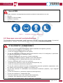
The following boxes are designed to attract the attention of the reader / user for the proper
and safe use of the machine:
Pay attention
This highlights behavioural rules to prevent damage to the machine and/or the occurrence of
dangerous situations.
m
o
Residual Risks
This highlights the presence of dangers that cause residual risks to which the operator must
pay attention in order to avoid injury or damage to property.
c
.i
1.1 Preface
For a safe and effective use of Electronic cutting band saw for bench Art. 0500, you
must read this manual carefully to acquire full knowledge of the machine and the general
precautions to be observed during operation. In other words, machine durability and
performance are strictly dependent on how it is used.
Even if already familiar with this sort of machines, it is necessary to follow the instructions
herein, in addition to the general precautions to be observed while working.
Acquire full knowledge of the machine.
Read this manual carefully to understand: operation, safety devices and all necessary
precautions. All this is to allow safe use of the machine.
Wear appropriate clothing for the job.
The operator must wear appropriate clothing, so as to prevent the occurrence of
unpleasant accidents.
Maintain the machine with care.
v
r
e
f
Using the Machine
The machine must only be used by qualified personnel trained to use the machine by
authorized personnel.
Pagina 6 di 32
MACHINES AND
ACCESSORIES
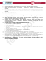
2
GENERAL SAFETY WARNINGS
2.1 General safety rules for machine tools
Risks related to Using the Machine
Do NOT underestimate the risks related to the use of the machine and stay focused on the
work you are carrying out.
m
o
Risks related to Using the Machine
Despite the implementation of all safety devices for safe use of the machine, it is necessary to
take note of all the accident prevention requirements highlighted in various parts of this
manual.
c
.i
Risks related to Using the Machine
Every person who is responsible for the use and maintenance of the machine should first have
read the instruction manual, particularly the chapter dealing with safety.
It is recommended that the plant safety manager get written confirmation of the above.
v
r
Risks associated with using the machine
During all work phases with the machine, you should proceed with great caution in
order to avoid damage to persons, to the property or to the machine itself.
Please use the machine only for its expected uses (drilling or tapping).
Don't tamper with the safety devices equipping the machine.
e
f
Risks associated with using the machine
Before starting any work on the machine, the operator must wear the appropriate personal
protective equipment (PPE) such as gloves and eye protection (see section 6.6 of this
manual).
1.
2.
3.
4.
5.
Always check the efficiency and integrity of the machine.
Before connecting the machine to the mains, make sure that the rotating parts are not
damaged or badly worn. Make sure that the switch is in the neutral position.
Do not start the machine in an enclosed or poorly ventilated area, or in the presence of
a flammable and/or explosive atmosphere. Do not use the machine in locations which
are damp, wet, or even exposed to the rain.
Avoid starting accidentally.
Before starting the machine, get used to ensuring that no remaining adjustment or
maintenance wrenches have remained inserted.
Pagina 7 di 32
MACHINES AND
ACCESSORIES
6.
7.
8.
9.
10.
11.
12.
13.
14.
15.
16.
17.
18.
Keep the workplace tidy and free from hindrances; disorder causes accidents.
Make sure that the work environment is forbidden to children, non-employees and
animals.
Do not perform tasks on the machine other than those for which it was designed. Only
use the machine in the manner in which it was intended, as described in this instruction
manual.
Work without disturbances.
Work areas must be well lit.
Always wear eye protection and protective gloves while working. If dust is produced, use
the appropriate masks.
Wear appropriate clothing. Loose clothing, dangling jewelry, long hair, etc.., can get
caught in moving parts, causing irreparable injury.
Replace worn and/or damaged parts. Before operating, make sure guards and
protections work correctly. If necessary, have them checked by Service staff. Use only
original spare parts.
Cut the mains voltage supply to the machine when:
the machine is not being operated;
is left unattended;
you are performing maintenance or adjustment because the machine does not work
properly;
you are replacing its tool;
in case the machine is being moved to another location;
you are cleaning the machine.
Do not use the machine in areas with a risk of fire and / or explosion.
It is recommended that users of this publication, for maintenance and repair, have a
basic knowledge of mechanical principles and of repair technique procedures.
Management in charge of safety is to make sure that the staff responsible for
using the machine has read and understood this manual in its entirety.
Management is responsible for safety and verification of the company's risk
status, pursuant to the law.
Pagina 8 di 32
e
f
v
r
c
.i
m
o
MACHINES AND
ACCESSORIES
2.2 Safety regulations regarding the electric system of machinetools
Risks associated with using the machine
1. Do not modify the electrical system in any way. Any attempt in this regard may
jeopardize the operation of electrical devices, causing malfunction or accident.
2. Work carried out in the electrical system of the machine must, therefore, be carried out
only by qualified and authorized personnel.
m
o
3. If you hear unusual noises, or you feel something strange, immediately stop the
machine. Then carry out an inspection and, if necessary, perform any repairs as
required.
1.
2.
3.
4.
5.
6.
The supply voltage must correspond to that stated on the identification plate and in the
technical specifications. Namely: 230 Vac / 50 Hz.
Never use any other type of power supply!
The use of a circuit breaker on the electric power supply is recommended. For more
detailed information, contact a trusted electrician.
The power socket must be equipped with a grounding lead. The size of any extension
cables must be equal to or greater than the one of the machine's own power supply cable
(diameter 1.5 mm2).
The power supply cable (and its possible extension cable) should never come in contact
with hot objects, sharp edges, wet or oiled surfaces.
The power supply cable (and its possible extension cable) should be checked periodically,
and before each use, for making sure they have no signs of damage or wear. If these are
not in good condition, do not use the machine and replace the damaged cable.
Do not use the power cord to detach its plug from the socket.
e
f
v
r
c
.i
2.3 Safety rules for band saws
1. Check in advance, the proper tightness between the material to be processed and
clamp.
2. Do not move away from the machine until the blade and other moving parts, have
completely stopped. For this purpose, only use the stop controls to stop the machine.
2.4 Technical Assistance
For any problems or concerns, please contact, without hesitation the Customer Service
Department of your dealer, who has competent and specialized staff, specific equipment and
spare parts.
2.5 Other provisions
IT IS FORBIDDEN TO TAMPER WITH SAFETY DEVICES
The first thing to do when starting work is to check for the presence and integrity of the
protections and the operation of the safety devices.
If any defect is detected, do not use the machine.
Even more so, it is strictly forbidden to modify or remove guards, safety devices,
labels and indication signs.
Pagina 9 di 32
MACHINES AND
ACCESSORIES
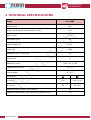
3 TECHNICAL SPECIFICATIONS
Model
Art. 0500
Height (mm)
580
Width (including the reference bar) (mm)
620
m
o
Depth (mm)
530
Net weight (kg)
20
Rated voltage (V)
c
.i
Power (W)
Frequency (80 - 16000 Hz)
Current (A)
v
r
Blade size (mm)
Blade speed (m/min)
Cutting angle
Bar section
0° (mm)
45° (mm)
e
f
230
1800
50
5
1140 x 13 x 0.65
20- 70
0° - 45°
105
100 x 105
55
55 x 60
Emitted acoustic power level (dB(A))
98
Vibration transmitted to the hand-arm system (m/s2)
2.0
Pagina 10 di 32
MACHINES AND
ACCESSORIES
4 DESCRIPTION OF THE MACHINE
The BENCH BAND SAW (Art. 0500) must only be used for cutting metal materials with the
characteristics indicated below and within the limits recommended by the manufacturer and
the safety and health norms.
The machine is designed and manufactured for cutting metal bars (section bars) with the
following characteristics:
circular section, solid or hollow, with a maximum diameter of 105 mm;
polygonal section, solid or hollow, with a maximum size of 105 mm;
m
o
Other types of use, or the extension of use beyond that envisaged, does not
correspond to the designation attributed by the manufacturer, and therefore the
latter cannot accept any responsibility for any damage resulting therefrom.
Intended use and materials
c
.i
The machine was designed and manufactured for a specific use, different uses and noncompliance with technical parameters established by the Manufacturer may be
hazardous to the operator.
In particular, regarding the type of material, DO NOT cut "hardened" or "casehardened" steel.
v
r
The Bench band saw consists of:
a fixed base;
the vice clamp to lock the piece;
the electric motor, the drive pulleys for the cutting blade and belt mounted on the
swivel head for the execution of angled machining;
the handle for manual operation and the rest of the commands.
Refer to paragraph 4.1 of this manual to view the different parts of the machine in detail.
The continuously adjustable speed motor, allows the cutting speed to be set for
each type of material.
e
f
The ergonomic handle ensures a solid and secure grip, moreover, the machine is
equipped with a sustained action start button to guarantee the safety required
during cutting.
The Band saw must be installed and used on flat supporting surfaces, with adequate
ergonomic and resistance features, such as a workbench or a base.
The Band saw can operate in closed work environments (production halls,
warehouses, etc.) or outdoors (construction sites, open spaces in general, etc.) .i.e.
protected from the weather and where there is no danger of fire or explosion.
The operating temperature is within the range of -20 / +50°C.
The environment must also be sufficiently illuminated so as to ensure operation in
maximum safety (at least 200 lux is recommended).
Pagina 11 di 32
MACHINES AND
ACCESSORIES
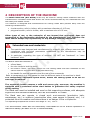
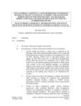
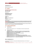
4.1 Main parts of the machine
8
6
7
5
9
10
m
o
11
12
c
.i
4
3
v
r
e
f
2
13
14
15
1
Figure 1 - Overview of the Machine
1
Base
2
Safety bracket for transport
10
Blade guide locking lever
3
Clamp activation lever
11
Blade guide
4
Clamp, piece-holder
12
Blade (belt)
5
Machine body
13
Electric motor
6
Saw tension lever
14
Rotation unit
7
Handle
15
Reference bars
8
Start button
Pagina 12 di 32
9
Belt speed adjustment knob
MACHINES AND
ACCESSORIES
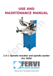
4.2 Identification label
The identification plate shown below is attached to the machine:
m
o
Figure 2 – Identification plate
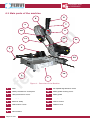
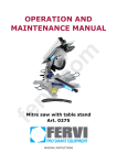
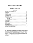
4.3 Pittogrammi
c
.i
The machine has the following pictograms:
IT IS STRICTLY FORBIDDEN TO:
Lubricate the blade: before, during and after use.
Operate without the guide blade installed and regularly placed;
Operate without the rear blade protection device;
Hold the piece to be cut with your hand.
v
r
e
f
Figure 3 – Prohibition pictograms on the machine.
Pagina 13 di 32
MACHINES AND
ACCESSORIES
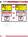
PLATE IN ITALIAN
PLATE IN ENGLISH
E’ ASSOLUTAMENTE VIETATO:
Lubrificare la lama: prima,
durante e dopo l’uso;
IT IS STRICTLY FORBIDDEN TO:
Lubricate the blade before, during
and after use.
Operare senza il guidalama
installato
e
regolarmente
posizionato;
Operate without the guide blade
installed and regularly placed;
Operate without the rear blade
protection device;
Operare senza la protezione
lama posteriore;
Hold the piece to be cut with your
hand.
Bloccare con le mani il pezzo
da tagliare.
m
o
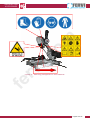
ATTENZIONE
ATTENTION
È VIETATO ESEGUIRE LAVORI SU
APPARECCHIATURE ELETTRICHE SOTTO
TENSIONE
EVENTUALI DEROGHE DEVONO ESSERE
AUTORIZZATE DAL CAPO RESPONSABILE
IN CONDIZIONI DI PARTICOLARE PERICOLO DEVE
ESSERE PRESENTE UN’ALTRA PERSONA OLTRE A CHI
ESEGUE IL LAVORO
INIZIARE I LAVORI SOLO AD AVVENUTA
ATTAZIONE DELLE MISURE DI SICUREZZA
c
.i
In ottemperanza al Dgs.81/08 relativo alla prevenzioni
infortuni
v
r
NON
RIMUOVERE
I DISPOSITIVI DI
SICUREZZA
e
f
Pagina 14 di 32
IT IS PROHIBITED TO WORK ON LIVE ELECTRICAL
EQUIPMENT
ANY EXCEPTIONS MUST BE APPROVED BY THE HEAD
MANAGER
UNDER PARTICULARLY DANGEROUS CONDITIONS,
ANOTHER PERSON MUST BE PRESENT WHO IS NOT
PERFORMING THE WORK
ONLY BEGIN WORKING WHEN SAFETY MEASURES
HAVE BEEN IMPLEMENTED
In accordance with Legislative Decree 81/08 on accident
prevention
DO NOT
REMOVE
SAFETY DEVICES
MACHINES AND
ACCESSORIES
c
.i
v
r
e
f
m
o
Figure 4 – Warning pictograms on the machine.
Pagina 15 di 32
MACHINES AND
ACCESSORIES
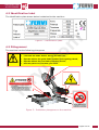
5 DESCRIPTION OF THE CONTROLS
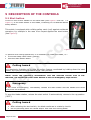
5.1 Start button
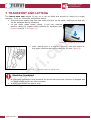
Found on the control handle of the band saw (see Figure 5 and ref. 7 in
Figure 1) is the start button of the blade, consisting of a sustained action
safety button.
This switch is equipped with a sliding safety catch (red) against accidental
operation, for example in the case of an impact against the start button
(see Figure 5).
c
.i
m
o
Figure 5 – Start button.
To perform the cutting operations, it is necessary to rotate the blade, i.e.:
move the safety catch down (yellow);
hold the start button down.
v
r
Cutting hazard
It is absolutely forbidden to by-pass the safety feature constituted by holding down the start
button, by trying to lock the button in the "ON" position.
e
f
NOTE: Given the operator's workstation and the reduced overall size of the
machine, the sustained action start button is also an emergency stop switch.
Emergency
In the event of emergency, immediately release the start button and the handle and move
away from the machine.
To stop the blade rotation, release the start switch. It automatically returns to the up position
("OFF").
Cutting hazard
After releasing the start switch, the blade continues to rotate by inertia.
Do not put body parts like hands and/or feet near the moving blade
Pagina 16 di 32
MACHINES AND
ACCESSORIES
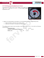
5.2 Cutting speed adjustment knob
Positioned at the base of the control handle of the Band saw
(see Figure 6 and ref. 9 in Figure 1) is the cutting speed
adjustment knob.
m
o
Figure 6 - Cutting speed knob
To adjust the cutting speed of the blade, turn the adjustment knob in the following way:
rotate clockwise to decrease the cutting speed;
rotate anti-clockwise to increase the cutting speed.
c
.i
The cutting speed must be set according to the material to be cut, in line with the following
specifications:
STAINLESS STEEL:
20 – 50
m/min
COPPER, ALUMINIUM AND ITS ALLOYS:
40 – 60
m/min
STEEL, ETC.:
50 – 70
m/min
e
f
v
r
Pagina 17 di 32
MACHINES AND
ACCESSORIES
6
MACHINE SAFETY DEVICES
6.1 Electrical safety devices
In the event of malfunction or breakdown, the BENCH BAND SAW is equipped with a power
cord and plug with a earthing lead that provides a path of minimal resistance to the electric
current; thus it reduces the danger of electrocution.
The plug must be plugged into an appropriate socket, grounded in accordance with current
regulation. Extension cables must be of a section equal to or greater than the power cable of
the machine.
m
o
Electric shock.
Improper connection of the machine’s grounding conductor can result in the risk of electric
shock.
c
.i
Check with a qualified electrician if you don't understand the grounding instructions
or if you have any doubts about grounding the machine.
6.2 Mechanical risk safety devices
6.2.1 Protective casing
They have the task of preventing parts of the operator's body, particularly hands and/or
fingers, from coming into direct contact with the bandsaw blade.
This prevents the splinters, dust or blade fragments that eventually get separated from being
thrown into the operator's face.
e
f
v
r
Checking the Safety devices
Each time you use the Bandsaw, check the proper functioning and integrity of the safety
devices.
6.2.2 Safety start switch
The control device of the Band saw has a safety switch (button) which is held down, with a
safety catch.
This prevents the danger of unwanted and/or accidental starts of the machine, since the
activation of the blade can only be started through a voluntary action suitable for the given
purpose (moving down the safety catch and pressing the button).
As said, the command requires maintained action, so the rotation of the blade continues until
the operator releases the button itself.
Pagina 18 di 32
MACHINES AND
ACCESSORIES
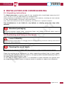
Use of PPE
In any case, ALWAYS use appropriate personal protective equipment such as:
Gloves;
Goggles or face shields;
Overalls or aprons;
Safety shoes.
m
o
c
.i
Figure 7 - Personal Protective Equipment.
6.3 Improper use and contraindications
The following actions described, which obviously can not cover the entire range of potential
possibilities of "misuse" of the machine, are to be considered strictly prohibited.
v
r
IT IS STRICTLY FORBIDDEN!!!
e
f
To use the machine without the guide blade installed and regularly placed;
To hold with the hand the piece to be cut;
To use the machine without the rear guard;
To use the machine for purposes other than those for which it is designed, in particular,
for cutting "hardened or cemented" steel;
To use the machine to cut wood or similar materials;
To exceed the cutting capacity stated by the manufacturer;
To leave the machine unattended with the plug inserted;
To allow untrained staff to use the machine;
To operate this machine if you are not psychophysically fit;
To use the machine without due attention;
To use the machine without the use of appropriate personal protective equipment, such
as, safety shoes and gloves, goggles or shields, etc.;
To use the machine in unforeseen environmental conditions (weather, high magnetic
fields, etc.);
To use the machine in potentially explosive atmospheres;
To use the machine in inadequate light;
To let the machine come into contact with foodstuffs;
To tamper with equipment and/or safety devices;
To lubricate the blade before, during and after processing.
Pagina 19 di 32
MACHINES AND
ACCESSORIES
7 TRANSPORT AND LIFTING
The BENCH BAND SAW weighs 20 kg, so it can be lifted and moved by hand by a single
operator. To do so, follow the instructions below:
Disconnect the power plug from the outlet and pick up the cable, making sure that will
not be damaged during transport;
Fix the upper blade holder casing, in the fully lowered
position using the proper safety bracket for transport (see
Figure 8 and ref. 2 in Figure 1);
m
o
Figure 8 – Close-up of bracket
c
.i
After making sure it is properly secured, hold the centre of
the upper machine casing and carefully lift (see Figure 9).
v
r
Figure 9 – Transporting the band saw.
e
f
Machine transport
All transport operations must ALWAYS be carried out when the machine is stopped and
no metal pieces are on the machine table.
ALWAYS disconnect the power plug.
Pagina 20 di 32
MACHINES AND
ACCESSORIES
8 INSTALLATION AND COMMISSIONING
8.1 Unpacking instructions
The BENCH BAND SAW is supplied ready for use, supplied with a band blade measuring 1140
mm x 13 mm x 0.65 mm and packed in a cardboard box.
Before disposing of packaging, check that no parts of the machine, including the user manual
or other documentation, are going to be thrown away.
Also, make sure that at the time of unpacking, the machine is in perfect condition.
The manufacturer is not liable for any defects or missing parts five days after
delivery.
m
o
Standard packaging
Packaging materials (plastic bags, polystyrene foam, etc.) must not be left within reach of
children as these are potentially dangerous.
c
.i
8.2 Positioning and fixing on the bench
Loss of Stability
Mount the Bench band saw on a surface that is solid and strong to avoid it falling over and so
it does not cause vibrations;
v
r
Cleaning the work bench
e
f
Before fixing the machine in place, clean the workbench of any dirt that may be present.
Place the machine on a workbench (or other supporting surface) that is level, stable
and sturdy and secure it with four bolts in the appropriate threaded fastening holes in
the base of the machine body (see ).
In the case of using a steel bench, it is advisable to place between the grinder and
the supporting surface a layer of material which is suitable to reduce the vibrations.
Pagina 21 di 32
MACHINES AND
ACCESSORIES
8.3 Connection of the electric power supply plug and start test
1. Insert the power supply plug into a grounded double pole socket (10/16 A, 230 V).
2. Start the machine by pressing the start button on the handle (see Figure 5) and make
sure that the direction of rotation of the blade is as indicated by the arrow on the
protective casing.
3. Before starting the cutting operation, check the saw as follows:
let it spin freely for at least 5 minutes;
with the protections in place;
without the presence of staff.
m
o
Collision of flying parts
During the test run, no operator and no other person should be within range of the machine.
v
r
c
.i
e
f
Pagina 22 di 32
MACHINES AND
ACCESSORIES
9 OPERATION
9.1 Instructions for Use
Operating the machine
The Bench band saw (Art. 0500) should only be used with certain metallic materials
(section bars, stainless steel, copper, aluminium and its alloys).
Do not cut "hardened or case-hardened" steel parts.
Do not cut pieces and/or structural steel exceeding the maximum permissible size (see
the Technical Specifications).
m
o
Risk of abrasion and accident
c
.i
Before using the machine, make sure that it is rigidly fixed to the workbench to prevent
unwanted movement or loss of stability.
Wear appropriate personal protective equipment (PPE) such as gloves, goggles, overalls
or aprons and safety shoes.
9.2 Adjustment of the machine and cutting
The machine is adjusted and used as follows:
v
r
1. Unlock the transport safety bracket, to
enable the use of the saw.
2. Lift the upper part of the machine by the
handle; in this position it should not descend
by itself. Otherwise, tighten the screw which
acts directly on the inner clutch of the
rotation unit (see Figure 10).
e
f
Figure 10 – Close-up of rotation unit screw.
3. Loosen the angle locking nut (ref. 16 in
Figura 11) and manually select the desired
cutting angle. In this regard, using the
graded scale present on the machine itself.
16
Figura 11 – Locking nut and graded scale.
Pagina 23 di 32
MACHINES AND
ACCESSORIES
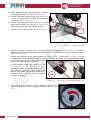
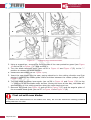
4. After selecting the desired angle, tighten
the angle locking nut (ref. 16 Figura 11).
5. Fit the reference rod into the hole (ref.17 in
Figure 12) and secure it with the headless
screw (ref.18 in Figure 12).
6. Loosen the knob (ref.19 in Figure 12) and
slide the movable rod (ref.20 in Figure 12)
determining the desired cutting height.
7. Tightly lock the knob (ref.19 in Figure 12).
20
18
19
m
o
c
.i
17
Figure 12 – Reference bar
1. Insert the piece / section bar to be cut within the clamp (ref.4 in Figure 1) resting it
against the piece stop element and tightening it by screwing the clamp actuation lever
(ref.3 in Figure 1).
Adjust the position of the guide blade unit (see Figure 13 and ref.11 in Figure 1) that,
in addition to being a useful guide for the band saw, also acts as a protection device to
cover the part of the blade that does
not serve the purpose of cutting.
In this regard, loosen the lever (ref. 21
in Figure 13) by turning it anticlockwise, slide the blade guide unit to
the desired position (the one that
leaves the blade uncovered as little as
possible) and relock the lever to secure
16
the unit in position.
v
r
e
f
Figure 13 - Close-up of the blade guide unit.
2. Set the cutting speed of the cutting machine by
adjusting the knob of the speed controller (see Figure
14).
Figure 14 - Cutting speed knob.
Pagina 24 di 32
MACHINES AND
ACCESSORIES
To adjust the cutting speed of the blade, turn the adjustment knob in the following
way:
rotate clockwise to decrease the cutting speed;
rotate anti-clockwise to increase the cutting speed.
The cutting speed must be set according to the material to be cut, in line with the
following specifications:
STAINLESS STEEL:
20 – 50
m/min
COPPER, ALUMINIUM AND ITS ALLOYS:
40 – 60
m/min
STEEL, ETC.:
50 – 70
m/min
3. Hold the handle, move the safety catch downwards, press the start
button and slowly lower the saw to start the cutting phase.
Cutting hazard
v
r
c
.i
e
f
m
o
Figure 15 – Start button.
It is absolutely forbidden to by-pass the safety feature constituted by holding down the start
button, by trying to lock the button in the "ON" position.
Emergency
In the event of emergency, immediately release the start button and the handle and move
away from the machine.
Cutting hazard
After releasing the start switch, the blade continues to rotate by inertia.
Do not put body parts like hands and/or feet near the moving blade
4. At the end of the cutting operation, release the starter button and wait for the blade to
stop completely, then loosen the clamp and remove the piece.
Pagina 25 di 32
MACHINES AND
ACCESSORIES
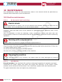
10 MAINTENANCE
Any maintenance, except for that specifically listed in this manual should be performed by
qualified staff authorized by the manufacturer.
10.1Routine maintenance
10.1.1
At the end of each machining
m
o
Electric shock
Before maintenance or checks, turn off the machine and ALWAYS unplug the plug from the
power outlet. This is so that there is no risk of electric shock.
Regularly clean and take care of the machine to guarantee proper efficiency and a long
working life.
Use a compressor to blow off shavings, chips, filings from cutting and dust that has
accumulated on the floor of the machine and on the workbench at the end of each machining
operation.
c
.i
Working with compressed air
v
r
ALWAYS wear the protective goggles when using compressed air.
Check the state of the Band saw and CE plate and warning plate at the same time; If they are
no longer legible ask for more.
Do not use the Band saw if there are any defects!!
Use only a dry cloth to clean the outside of the machine.
e
f
Cleaning the machine
DO NOT use detergents or any solvents; the plastic parts are easily damaged by chemical
agents.
10.1.2
Periodically
Every 6 months of the machine’s life, perform a thorough inspection of operation and wear.
Disconnect the power supply and check the length and efficiency of the electric motor
brushes, which should not be less than 6 mm. Otherwise, replace them with identical parts.
The gear transmission does not require any maintenance.
Pagina 26 di 32
MACHINES AND
ACCESSORIES
10.2Changing the bandsaw blade
Electric shock
Before replacing the blade, turn off the machine and ALWAYS remove the plug from the power
outlet. This is so that there is no risk of electric shock or undesired activation of the machine.
Wear PPE
m
o
ALWAYS wear suitable protective gloves (to reduce the risk of cut) when replacing the blade.
When you notice excessive wear in the teeth of the blade, with the resulting loss of the ability
to cut, replace it. In this regard, use a replacement blade with equivalent characteristics to
those indicated by the manufacturer (see Technical Specifications).
c
.i
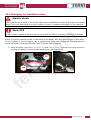
1. Using the knob (see ref.27 in Figure 16 and Figure 17/B), unscrew the fixing screw for
the angular plate of the moveable blade guide, then remove it.
27
v
r
29
e
f
Figure 16 – A: Guide blade and blade tensioning lever, B: Rear guard.
.
Pagina 27 di 32
MACHINES AND
ACCESSORIES
A
m
o
B
c
.i
C
D
v
r
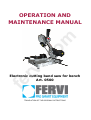
Figure 17 - Changing the bandsaw blade.
2. Using a screwdriver, remove the fixing screws of the rear protection guard (see Figure
16 and ref.28 in Figure 17/C) and remove it.
3. Turn the blade tensioner lever (see ref.29 in Figure 16 and Figure 17/D) to the "-"
position to release the blade tension.
4. Extract the saw blade (ref.30 Figure 17/D).
5. Insert the new blade into the saw, paying attention to the cutting direction and first
placing it between the blade guide rollers and then between the rubber pulleys (ref.31
Figure 17/D).
6. Turn the blade tensioner lever again (see ref.29 in Figure 16 and Figure 17/D) to the
"+" position to put the blade under tension. Moving the lever all the way, the blade will
automatically go into cutting position when the motor begins to turn.
7. Remount the guard (see Figure 16 and ref.28 in Figure 17/C) and the angular plate of
the moveable blade guide (see ref.27 in Figure 16 and Figure 17/B).
e
f
First cut with new blades
To preserve the effectiveness of the blade over time, do not use maximum cutting pressure
during the first 4-6 cuts.
Pagina 28 di 32
MACHINES AND
ACCESSORIES
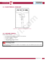
11 ELECTRICAL CIRCUIT
m
o
c
.i
Figure 18 - Diagram of the electrical circuit
v
r
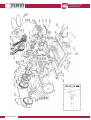
12 SPARE PARTS
Always clearly indicate:
the symbol and the serial number of the machine;
the code number of the parts;
number of parts;
exact address of your company.
e
f
Genuine Parts
The manufacturer disclaims any liability for damages of any kind caused by the use of nonoriginal spare parts.
Pagina 29 di 32
MACHINES AND
ACCESSORIES
v
r
c
.i
e
f
Pagina 30 di 32
m
o
MACHINES AND
ACCESSORIES
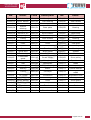
No.
Descr.
Code
Description
No.
Descr.
05000/01
Plain bearing
0500/28
Rear jaws
0500/55
Switch
05000/02
Nylon washer
0500/29
Plain bearing
0500/56
Rear handle
05000/03
Slide
0500/30
Sliding jaws
0500/57
Secondary gear
05000/04
Special
bushing
0500/31
Base plate
0500/58
Bearing
05000/05
Spring holder
0500/32
Special chassis
0500/59
Slot
05000/06
Eccentric pin
0500/33
Nylon washer
0500/60
Head body
05000/07
Spring
0500/34
Swivel body
0500/61
Lever
05000/08
Casing
0500/35
Rear bracket
0500/62
Bearing
Extension cord 0500/36
Front bracket
0500/63
Intermediate gear
0500/64
Final gear
0500/65
Bearing
0500/66
Bearing
0500/67
Gasket
0500/68
Cover
0500/69
Drive pulley
0500/10
Lever
0500/37
0500/11
S.F. screw
0500/38
5000/12
Base
0500/39
Fixed bar
0500/13
Spiral door
0500/40
Brush cover
0500/14
Elastic ring
0500/41
Brush
0500/15
Fixed blade
guide
0500/42
Brush holder
0500/16
Door mat
0500/43
Motor body
m
o
0500/70
Special nut
0500/17
Mat
0500/44
Nameplate
0500/71
Blade
0500/18
Bearing
0500/45
Cable with plug
0500/72
Duct pulley
0500/19
Bearing
0500/46
Stator
0500/73
Special washer
0500/20
Casing
0500/47
Conveyor
0500/74
Sliding guide
blade
0500/21
T.E. screw
0500/48
Connection
0500/75
Adjustable lever
0500/22
Shaft
0500/49
Electronic regulator
0500/76
Locking lever
0500/23
Nylon washer
0500/50
Knob
0500/77
Small guard
0500/24
Spring
0500/51
Nameplate
0500/78
Terminal cover
0500/25
FE washer
0500/52
Terminal
0500/79
Feet
0500/26
Ratchet
0500/53
Grommet
0500/27
Special screw
0500/54
Front handle
05000/09
Knob
c
.i
Lock bar
v
r
e
f
Pagina 31 di 32
MACHINES AND
ACCESSORIES
13 TROUBLESHOOTING
PROBLEM
PROBABLE CAUSE
Noisy operation.
A) Damaged bearings.
B) Bearings not lubricated.
C) Blade friction.
D) Blade loose.
The motor will not
start.
A)
B)
C)
D)
E)
Electrical power supply.
Electrical connections.
Burnt motor windings.
Blown fuses.
Broken switch.
Poor cutting
efficiency or
excessive
overheating of the
blade.
A) Excessive pressure on
the workpiece.
B) Blade worn or does not
cut well.
C) Material too hard.
SOLUTION
A) Contact Technical Support.
B) Lubricate.
C) Remove / replace the blade and
check sliding.
D) Turn the blade tension lever.
m
o
A) Check the mains power supply.
B) Check the wiring connections.
C) Contact Technical Support.
D) Replace the fuses.
E) Contact technical support.
A) Apply less pressure.
c
.i
14 WAREHOUSE STORAGE
v
r
B) Check the blade sharpness and
wear.
C) Lubricate as you work.
In the event that the machine should be stored and unused for some time, it must be kept in
a closed environment free of moisture to avoid damage and/or deterioration.
15 DISPOSAL OF PARTS AND MATERIALS
If the machine is to be scrapped, its parts must be disposed of separately.
e
f
Respect the Environment!
Contact a specialist centre for the collection of metallic materials.
The structure of the Band saw and the blade is made from steel, while
some parts such as the handle, the casing of the electric motor, etc. are
made from polymeric material. In this regard, differentiate the materials
according to their nature, with the assistance of specialist companies
authorized for waste disposal, in compliance with the requirements of the
law.
Respect the environment!
Dispose of cuttings (chips, filings cutting etc..) In accordance with local regulations.
Pagina 32 di 32