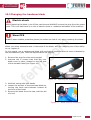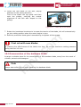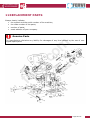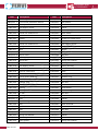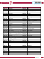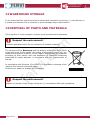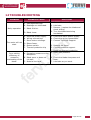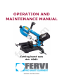
1
fe rv i.c om OPERATION AND MAINTENANCE MANUAL Cutting band saw Art. 0362 ORIGINAL INSTRUCTIONS MACHINES AND ACCESSORIES FOREWORD Read this manual before operating any machinery Operator Qualification om ORIGINAL INSTRUCTIONS Before starting any operation it is compulsory to read this instruction manual. The guarantee that the machine will function and perform properly is strictly dependent upon the application of all the instructions contained in this manual. fe rv i.c The operators assigned to using this machine must be supplied with all of the necessary information and instruction and should be provided with adequate training regarding safety in pertaining to: a) The conditions of use of the equipment; b) Foreseeable abnormal situations, pursuant to Article 73 of Legislative Decree 81/08. We guarantee the Machine's conformity to the specifications and technical instructions described in the Manual on the date of issuance and listed herein; On the other hand, the machine may also be subject to important technical changes in the future, without the manual being updated. Therefore, see FERVI for information about modifications that could be implemented. REV. 2 Page 2 of 34 October 2013 MACHINES AND ACCESSORIES CONTENTS 1 INTRODUCTION ........................................................................................ 4 2 SAFETY WARNINGS .................................................................................. 5 2.1 2.2 2.3 2.4 General safety rules for machine tools.......................................................................5 Safety regulations regarding the electric system of machine-tools ............................7 Technical support.......................................................................................................7 Other provisions ........................................................................................................7 3 TECHNICAL SPECIFICATIONS ................................................................... 8 4 DESCRIPTION OF THE MACHINE ............................................................... 9 SAFETY DEVICES ON THE MACHINE ........................................................ 18 5.1 5.2 Electrical safety devices........................................................................................... 18 Mechanical risk safety devices ................................................................................. 18 rv i.c 5 om 4.1 Main machine parts.................................................................................................. 10 4.2 Plate and pictograms ............................................................................................... 11 4.2.1 Translation of the plates ........................................................................................ 14 4.3 Description of controls ............................................................................................. 15 4.3.1 Head locking lever ................................................................................................ 16 4.3.2 Vice adjustment screw........................................................................................... 17 4.3.3 Blade tension adjustment handwheel....................................................................... 17 4.3.4 Adjusting the blade cover ...................................................................................... 17 6 IMPROPER USE AND CONTRAINDICATIONS............................................ 20 7 TRANSPORT AND LIFTING ...................................................................... 21 7.1 ASSEMBLY AND COMMISSIONING .......................................................... 22 8.1 8.2 9 Unpacking instructions ............................................................................................ 22 Connection to the power supply and start-up test ................................................... 22 OPERATION ............................................................................................ 23 9.1 9.2 9.3 9.4 9.5 fe 8 Machine transport .................................................................................................... 21 Instructions for Use ................................................................................................. 23 Setting the speed ..................................................................................................... 23 Commissioning and adjustments ............................................................................. 24 Performing cutting ................................................................................................... 24 Performing cutting ................................................................................................... 25 10 MAINTENANCE ........................................................................................ 26 10.1 10.2 10.3 Routine maintenance ............................................................................................ 26 Changing the bandsaw blade ................................................................................ 27 Conservation of the bandsaw blade ...................................................................... 28 11 REPLACEMENT PARTS ............................................................................. 29 12 WAREHOUSE STORAGE ........................................................................... 32 13 DISPOSAL OF PARTS AND MATERIALS.................................................... 32 14 TROUBLESHOOTING................................................................................ 33 15 WIRING PLAN ......................................................................................... 34 Page 3 of 34 MACHINES AND ACCESSORIES 1 INTRODUCTION The purpose of this manual is to provide the knowledge necessary for the use and maintenance of the metal band saw and create a sense of responsibility and knowledge of the capabilities and limitations of the device entrusted to the operator. As the machine is entrusted to experienced and skilled operators, the following machine must be perfectly known by the operator if you want it to be used safely and effectively. Personnel selection is important for efficiency and safety, and staff selected for a particular job must have sufficient physical and mental capabilities to learn from training. Pay attention om GRAPHIC REPRESENTATION OF SAFETY, OPERATIONAL AND RISK WARNINGS The following boxes are designed to attract the attention of the reader / user for the proper and safe use of the machine: rv i.c This highlights behavioural rules to prevent damage to the machine and/or the occurrence of dangerous situations. Residual Risks This highlights the presence of dangers that cause residual risks to which the operator must pay attention in order to avoid injury or damage to property. fe For safe and easy operation of the cutting band saw for metals, this manual must be read carefully in order to acquire the necessary knowledge. In other words, the life and performance of the machine are dependent on how it is used. Even if already familiar with the machine, it is necessary to follow the instructions contained herein, in addition to the general precautions to be observed while working. Acquire full knowledge of the machine. Read this manual carefully to understand: operation, safety devices and all necessary precautions. All this is to allow safe use of the equipment. Wear appropriate clothing for the job. The operator must wear appropriate clothing, so as to prevent the occurrence of unpleasant accidents. Maintain the machine with care. Machine operation The machine must only be used by qualified personnel trained to use the machine by authorized personnel. Page 4 of 34 MACHINES AND ACCESSORIES 2 SAFETY WARNINGS 2.1 General safety rules for machine tools Risks associated with using the machine om DO NOT underestimate the risks associated with using the machine and concentrate on the work in progress. Despite the implementation of all safety devices for safe use of the machine, it is necessary to take note of all the accident prevention requirements highlighted in various parts of this manual. Risks associated with using the machine rv i.c Every person who is responsible for the use and maintenance of the machine should first have read the instruction manual, particularly the chapter dealing with safety. It is recommended that the plant safety manager get written confirmation of the above. Operator Protection fe Before starting any work on the machine, the operator must wear the appropriate personal protective equipment (PPE), such as goggles, gloves and non-slip shoes. 1. Read this manual carefully, in order to work safely. 2. Always check the efficiency and integrity of the machine. 3. Do not start the machine in a poorly ventilated area, or in the presence of a flammable and/or explosive atmosphere. Do not use the machine in damp and/or wet places. Do not expose it to rain. 4. Before use, check that the support surface of the machinery is flat, of suitable strength and of sufficient ergonomics. 5. Avoid starting accidentally. 6. Before starting the machine, get used to ensuring that no remaining adjustment or maintenance wrenches have remained inserted. 7. Check in advance, that the workpiece is properly secured between the jaws of the vice. 8. Keep the workplace tidy and free from hindrances; disorder causes accidents. 9. Make sure that the work environment is forbidden to children, non-employees and animals. 10. Do not perform tasks on the machine other than those for which it was designed. Only use the machine in the manner in which it was intended, as described in this instruction manual. Page 5 of 34 MACHINES AND ACCESSORIES fe rv i.c om 11. Work without disturbances. 12. Work areas must be well lit. 13. Always wear eye protection and protective gloves while working. If dust is produced, use the appropriate masks. 14. Wear appropriate clothing. Loose clothing, dangling jewellery, long hair, etc., can get caught in the moving parts, causing irreparable injury. 15. Do not move away from the machine until the blade and other moving parts, have completely stopped. For this purpose, only use the stop controls to stop the machine. 16. Replace worn and/or damaged parts, check that the repairs and protections work properly before operating. If necessary, have the machine checked by the service support personnel. Use only original spare parts. 17. Unplug the power cord of the machine when : the machine is not being operated; is left unattended; you are performing maintenance or adjustment because the machine does not work properly; the power cable is damaged; replace the tape (blade); in case the machine is being moved to another location; you are cleaning the machine. 18. It is recommended that users of this publication, for maintenance and repair, have a basic knowledge of mechanical principles and of repair technique procedures. 19. Management in charge of safety is to make sure that the staff responsible for using the machine has read and understood this manual in its entirety. 20. Management is responsible for safety and verification of the company's risk status according to Legislative Decree 81/08 and subsequent modifications and amendments. Page 6 of 34 MACHINES AND ACCESSORIES 2.2 Safety regulations regarding the electric system of machinetools Changes in the Electrical System Do not modify the electrical system of the machine in any way. Work carried out in the electrical system of the machine must be carried out only by authorized personnel. If one hears unusual noises, or feels something strange, immediately stop the machine. Carry out an inspection and, if necessary, perform any repairs as required. fe rv i.c om 1. The supply voltage must correspond to that stated on the label and in the technical specifications: 230 V / 50 Hz 2. Never use any other type of power supply! 3. The use of a device for the automatic interruption of the power supply is necessary, coordinated with the on-board machine system, capable of detecting short circuits, overcurrents and ground faults. 4. The power plug must have a grounding conductor. 5. Any extension cords must be of equal or greater length than the power cord on the machine and must also be equipped with a grounding connection. 6. The power supply cable (and its possible extension cable) should never come in contact with hot objects, sharp edges, wet or oiled surfaces. 7. The power cord should be checked regularly and before each use to check for signs of damage or wear. 8. If these are not in good condition, do not use the machine and replace the cable immediately. 9. Do not use the power cord to detach its plug from the socket. 10.Do not switch off the machine by unplugging it. 2.3 Technical support For any problems or concerns, please do not hesitate to contact the dealer who sold the item. 2.4 Other provisions IT IS FORBIDDEN TO TAMPER WITH SAFETY DEVICES The first thing to do when starting work is to check for the presence and integrity of the protections and the operation of the safety devices. If any defect is encountered do not use the machine! It is strictly forbidden to modify or remove guards, safety devices, labels and caution signs. Page 7 of 34 MACHINES AND ACCESSORIES 3 TECHNICAL SPECIFICATIONS Description (unit of measurement) Art. 0362 Height (mm) 450 Width (mm) 700 Depth (mm) 360 Net weight (kg) 22 Power (W) Frequency (Hz) Blade size (mm) Cutting angle Bar section 0° (mm) 45° (mm) fe 60 ° (mm) rv i.c Blade speed (m/min) Page 8 of 34 230 om Rated voltage (V) 500 50 1435 x 12.7 x 0.65 35- 80 0° ÷ 60° 125 125 x 125 130 x 125 76 76 x 76 76 x 90 76 53 x 53 53 x 76 MACHINES AND ACCESSORIES 4 DESCRIPTION OF THE MACHINE The Cutting band saw must only be used for cutting metal materials with the characteristics indicated below and within the limits recommended by the manufacturer. The machine is designed and manufactured for cutting metal bars (section bars) with the following characteristics: circular section, solid or hollow, with a maximum diameter of 125 mm; circular section, solid or hollow, with a maximum size of 125 mm; circular section, solid or hollow, with maximum dimensions of 125x130 mm. om Other types of use, or the extension of use beyond that envisaged, does not correspond to the designation attributed by the manufacturer, and therefore the latter cannot accept any responsibility for any damage resulting therefrom. Intended use and materials The machine was designed and manufactured for a specific use, different uses and noncompliance with technical parameters established by the Manufacturer may be hazardous to the operator. In particular, with regard to the type of material: DO NOT TRY TO SAW "hardened" or "cemented" steel. rv i.c fe The band saw consists of: the base; the vice clamp to lock the piece; the moveable swivel head, on which are installed the electric motor, the pulleys and the blade; the lever with handle and blade start button. Refer to section 4.1 of this manual to view the different parts of the machine in detail. The band saw art. 0362 has a continuously adjustable rotation speed, from a minimum of 35 m/min to a maximum of 80 m/min. The adjustment can be made by means of a potentiometer located on the motor housing. Figure 1 – Speed adjustment. The band saw for metal must be installed and used on flat supporting surfaces, with suitable ergonomic characteristics and strength. The machine can only be operated in closed work environments (production halls, warehouses, etc.), where there is no danger of fire or explosion. The operating temperature is within the range of +5 / +50°C. The environment must also be sufficiently illuminated so as to ensure operation in maximum safety (at least 200 lux is recommended). Page 9 of 34 MACHINES AND ACCESSORIES 4.1 Main machine parts 6 7 8 9 1 11 5 om 12 4 13 2 fe 1 rv i.c 3 Figure 2 – Close-up of the main parts of the saw. 1 Support base 8 Guide blade and sliding shield 2 Head locking lever 9 Start/Stop buttons 3 Vice closing screw 10 Electric motor 4 Workpiece clamping vice 11 Identification plate 5 Blade tension handwheel 12 Speed regulator 6 Swivel and movable head 13 Head locking pin 7 Handle Page 10 of 34 MACHINES AND ACCESSORIES 4.2 Plate and pictograms d om On each machine there is: a) an identification plate on the motor casing box; b) a pictogram with main safety rules, on the front of the movable head; c) a pictogram indicating the direction of blade rotation, on the movable head; d) a pictogram with the rotation direction of the blade tensioner; e) the graduated scale for the inclination of the movable head; f) the graduated scale for adjusting the speed of rotation; g) reset for thermal protection of the motor; h) a pictogram indicating the prohibition to remove the guards at the back of the movable head. See the following figure. b c a f h e fe rv i.c g Figure 3 – Position of the plates and pictograms. a) Identification plate Page 11 of 34 MACHINES AND ACCESSORIES b) Pictogram with the main safety rules ATTENTION rv i.c om For your own Safety please read and ensure you understand the instruction manual before using the machine. Do not expose the machine to rain or use in damp places. Do not wear jewellery or loose clothing while using the machine. Wear protective goggles or face shields during use. Always make check the tension of the blade, the guides and the bearings. Maintain adequate protection devices in the place where the machine is used. Keep your hands at a safe distance from the operating area of the blade. Do not rotate the head when the blade is in motion or when the head is lowered. Clamp the workpiece firmly in the vice and do not hold it with your hands. fe c) Pictogram indicating the direction of rotation of the blade d) Pictogram for adjusting the blade tensioner Page 12 of 34 MACHINES AND ACCESSORIES e) Graduated scale for the inclination of the movable head rv i.c om f) Graduated scale for adjusting the speed of the blade fe g) Reset for thermal protection of the motor h) Pictogram indicating the prohibition of removing the guards Page 13 of 34 MACHINES AND ACCESSORIES 4.2.1 Translation of the plates PLATE IN ITALIAN PLATE IN ENGLISH ATTENZIONE ATTENTION È VIETATO ESEGUIRE LAVORI SU APPARECCHIATURE ELETTRICHE SOTTO TENSIONE EVENTUALI DEROGHE DEVONO ESSERE AUTORIZZATE DAL CAPO RESPONSABILE IN CONDIZIONI DI PARTICOLARE PERICOLO DEVE ESSERE PRESENTE UN’ALTRA PERSONA OLTRE A CHI ESEGUE IL LAVORO INIZIARE I LAVORI SOLO AD AVVENUTA ATTUAZIONE DELLE MISURE DI SICUREZZA IT IS PROHIBITED TO WORK ON LIVE ELECTRICAL EQUIPMENT ANY EXCEPTIONS MUST BE APPROVED BY THE HEAD MANAGER UNDER PARTICULARLY DANGEROUS CONDITIONS, ANOTHER PERSON MUST BE PRESENT WHO IS NOT PERFORMING THE WORK ONLY BEGIN WORKING WHEN SAFETY MEASURES HAVE BEEN IMPLEMENTED In ottemperanza al D.Lgs. 81/08 relativo alla prevenzione infortuni In accordance with Legislative Decree 81/08 on accident prevention Per la Vostra Sicurezza si prega di leggere e capire il manuale d’istruzioni prima dell’uso della macchina. Non esporre la macchina a pioggia o usare in luoghi umidi. Non indossare abiti lesi o gioielli durante l’utilizzo della macchina. Indossare occhiali protettivi o schermi facciali durante l’uso. Accertarsi sempre sull’adeguato tensionamento della lama, delle guide e dei cuscinetti. Mantenere le adeguate protezioni nel luogo ove si utilizza la macchina. Mantenere le mani a distanza di sicurezza dalla zona di lavorazione della lama. Non ruotate la testa quando la lama è in movimento o quando la testa è abbassata. For your own Safety please read and ensure you understand the instruction manual before using the machine. Do not expose the machine to rain or use in damp places. Do not wear jewellery or loose clothing while using the machine. Wear protective goggles or face shields during use. Always make check the tension of the blade, the guides and the bearings. Maintain adequate protection devices in the place where the machine is used. Keep your hands at a safe distance from the operating area of the blade. rv i.c ATTENTION om ATTENZIONE Bloccate saldamente il pezzo da lavorare nella morsa e non trattenetelo con le mani. ATTENZIONE fe AL FINE DI EVITARE INCIDENTI È VIETATO RIMUOVERE LE PROTEZIONI DURANTE L’USO. Page 14 of 34 Do not rotate the head when the blade is in motion or when the head is lowered. Clamp the workpiece firmly in the vice and do not hold it with your hands. ATTENTION TO PREVENT ACCIDENTS IT IS FORBIDDEN TO REMOVE THE PROTECTION DEVICES DURING USE. MACHINES AND ACCESSORIES 4.3 Description of controls The electrical and control panel is installed on the right side of the machine (see figure 4). 1 om 2 Figure 4 – Start/Stop Buttons fe rv i.c Start button (1) This has the function of disconnecting the power supply. When pressed, the motor is powered. Stop button (2) To disconnect the machine from the power supply, press the 0 button. 3 Figure 5 – Confirmation button. Manual control button (3) On the handle located on the control lever of of the movable head, there is the button for blade activation in manual mode (ref. 3 in Figure 5). This button is a command that requires a human presence (or is held down), in the sense that the blade rotates while the button continues to be pressed down. Conversely, when releasing the button the saw blade stops immediately. This button is equipped with a device for protection against accidental and undesired operation, for example in the event of a collision. To perform manual cutting operations: Page 15 of 34 MACHINES AND ACCESSORIES hold the handle with your right hand and place your index finger inside the protection ring; press and hold down the button (3). Cutting hazard It is absolutely forbidden to by-pass the safety feature constituted by holding down the start button, by trying to lock the button in the "PRESSED" position. While working, keep your left hand away from the cutting area and the blade. Otherwise, it could lead to serious personal injury! om During manual operation, with the start switch held down, this button also performs the function of emergency stop when released. How to act in the event of an emergency rv i.c During manual operation, in the event of an emergency, immediately release the start button (3) and move away from the machine. 4.3.1 Head locking lever fe At the front of the saw, under the coolant collection tank and the vice, the locking lever of the saw head is located. This lever is used to rotate the head when it is necessary to make angled cuts (with angles from 0 to 60°). Lever to the left (A): head unlocked. Lever to the right (B): head locked. B A Figure 6 – Head locking lever. Page 16 of 34 MACHINES AND ACCESSORIES 4.3.2 Vice adjustment screw Located at the front of the band saw is the vice tightening screw. Screw clockwise: to clamp the workpiece in the vice. Screw anti-clockwise: to unlock the workpiece in the vice. Figure 7 – Vice adjustment screw. 4.3.3 Blade tension adjustment handwheel rv i.c om At the front part of the head, there is a handwheel for adjusting the tension of the blade. Handwheel clockwise: to increase the tension of the blade (TIGHTEN). Handwheel anti-clockwise: to reduce the tension of the blade (LOOSEN). Figure 8 – Blade tension handwheel. fe 4.3.4 Adjusting the blade cover At the point where the blade exits its casing, so as to leave the cutting part of the blade exposed, there is an adjustable blade cover. A lever locks it in position. Lever to the right: blade cover unlocked. Lever to the left: blade cover locked. Figure 9 - Blade cover locking lever. Page 17 of 34 MACHINES AND ACCESSORIES 5 SAFETY DEVICES ON THE MACHINE 5.1 Electrical safety devices In the event of malfunction or breakdown, the BAND SAW is equipped with a power cable with a grounding connection, which provides a path of least resistance for electric current and reduces the risk of electric shock. The plug must be plugged into an appropriate outlet, earthed in accordance with current regulations. Extension cables must be of a section equal to or greater than the power cable of the machine. om Electric shock. Improper connection of the machine’s grounding conductor can result in the risk of electric shock. rv i.c Check with a qualified electrician if you don't understand the grounding instructions or if you have any doubts about grounding the machine. fe SAFETY START SWITCH The control device of the Band saw has a safety switch (button) which is held down (human presence required). This prevents the danger of unwanted and/or accidental starts of the machine, since the activation of the blade can only be activated through a voluntary action suitable for the given purpose. As said, the command requires maintained action, so the rotation of the blade continues until the operator releases the button itself. 5.2 Mechanical risk safety devices PROTECTIVE CASING They have the task of preventing parts of the operator's body, particularly hands and/or fingers, from coming into direct contact with the bandsaw blade. Furthermore, this prevents the splinters, workpiece or blade fragments that eventually get separated from being thrown towards the operator's face. Checking the Safety devices Each time you use the band saw, check the proper functioning and integrity of the safety devices. Page 18 of 34 MACHINES AND ACCESSORIES Use of PPE In any event, ALWAYS use appropriate personal protective equipment (PPE, see Figure 10) such as: Gloves Goggles or face shields om Safety shoes Overalls or aprons fe rv i.c Figure 10 – Personal Protective Equipment. Page 19 of 34 MACHINES AND ACCESSORIES 6 IMPROPER USE AND CONTRAINDICATIONS The following actions described, which obviously can not cover the entire range of potential possibilities of "misuse" of the machine, are to be considered strictly prohibited. IT IS STRICTLY FORBIDDEN! fe om To use the machine without the guide blade installed and regularly placed; To hold the piece to be cut with your hand; To use the machine for purposes other than those for which it is designed, in particular, for cutting steel "hardened or cemented"; To use the machine to cut wood or similar materials; To exceed the cutting capacity stated by the manufacturer; To leave the machine unattended with the plug inserted; To allow untrained staff to use the machine; To operate this machine if you are not psychophysically fit; To use the machine without due attention; To use the machine in the presence of strangers, children or animals; To use the machine without the use of appropriate personal protective equipment, such as shoes and safety gloves, goggles or shields; To use the machine in unforeseen environmental conditions (weather, high magnetic fields, etc.); To use the machine in potentially explosive atmospheres; To use the machine in inadequate light; To let the machine come into contact with foodstuffs; To tamper with equipment and/or safety devices; rv i.c Page 20 of 34 MACHINES AND ACCESSORIES 7 TRANSPORT AND LIFTING 7.1 Machine transport om The transport of the machine must be carried out using closed vans, in order to protect the machine from the elements. The dimensions must be suitable for the load to be transported. The BAND SAW weighs around 22 kg, so it can be lifted and moved by hand by a single operator. To do so it is necessary to: lock the movable head using the appropriate locking pin, check that the power cord is not connected to the mains, hold the machine under the base, with both hands; Figure 11 - Locking pin. The machine is supplied in a cardboard box. rv i.c Machine transportation fe All transportation operations are ALWAYS made when the machine is stopped and there are no metal workpieces in the machine vice. ALWAYS disconnect the power plug. Page 21 of 34 MACHINES AND ACCESSORIES 8 ASSEMBLY AND COMMISSIONING 8.1 Unpacking instructions Standard packaging om The BAND SAW is delivered packed inside a cardboard box. Before disposing of packaging, check that no parts of the machine, including the user manual or other documentation, are going to be thrown away. Also, make sure that at the time of unpacking, the parts of the machine are in perfect condition. The manufacturer is not liable for any defects or missing parts five days after delivery. rv i.c Packaging materials (plastic bags, polystyrene foam, etc.) must not be left within reach of children as these are potentially dangerous. 8.2 Connection to the power supply and start-up test fe 1. Insert the power supply plug into a grounded double pole socket (10/16 A, 250 V). 2. Press the start button so that it is in the ON position and then press the button on the handle to make sure that the rotation direction of the blade is the same as that indicated by the arrow on the protective casing. 3. Before starting the cutting operation, check the saw as follows: let it spin freely for at least 5 minutes with the protection devices in place without the presence of staff. Impact of thrown parts During the test run, no operator and no other person should be within range of the machine. Page 22 of 34 MACHINES AND ACCESSORIES 9 OPERATION 9.1 Instructions for Use Machine operation The band saw should only be used with certain metallic materials (structural steel, stainless steel, copper, aluminium and its alloys). Do not cut "hardened or case-hardened" steel parts. Do not cut pieces and/or structural steel exceeding the maximum permissible size (see the Technical Specifications). om Risk of abrasion and accident Before using the machine, make sure that it is rigidly fixed to the floor to prevent unwanted movement or loss of stability. Wear appropriate personal protective equipment (PPE) such as gloves, goggles, overalls or aprons and safety shoes. rv i.c 9.2 Setting the speed fe The band saw can operate at different speeds, depending on the material being cut. To set the rotation speed of the band just rotate the speed regulator located on the motor casing box: 1 – to select the lowest speed 35 m/min 6 – to select the highest speed 80 m/min Figure 12 – Speed selection. Page 23 of 34 MACHINES AND ACCESSORIES 9.3 Commissioning and adjustments The machine is adjusted and used as follows: 1. To adjust the position of the head and perform angled cuts between 0 and 60° it is necessary to rotate the lever, located at the front right of the machine, backwards into the unlocked position (see Figure 13) then manually rotate the head aligning the indicator along the graduated scale to the desired position. 2. After positioning the head, rotate the lever forward, Adjusting the head Remember to always lock the head before starting the cut. Otherwise, sudden movements are possible with consequent breaking of the belt. Do not exceed the cutting capacity, angled positions correspond to smaller sizes, check the specifications given on page 8. The values on the graduated scales are indicative, if precision cutting is needed more precise means will be required. rv i.c Figure 13 – Adjusting the head position. om into the locked position. 9.4 Performing cutting After making the above adjustments it is possible to carry out the cutting of the section bar. Fire or explosion fe Some metallic materials (such as magnesium) may generate chips which are easily flammable. Proceed with caution when removing them and cleaning the machine. 1. Insert the piece / section bar to be cut within the vice resting it against the fixed jaws (piece-holder) and then approach the movable jaw by rotating the vice tightening screw clockwise (Figure 14). Figure 14 – Adjustment and locking of the vice. Page 24 of 34 MACHINES AND ACCESSORIES 2. Adjust the position of the guide blade unit (see Figure 15) that, in addition to being a useful guide for the band saw, also acts as a protection device to cover the part of the blade that does not serve the purpose of cutting. 9.5 Performing cutting om Figure 15 – Unlocking the blade guide screw. To do this: Loosen the fixing screw by turning the locking lever anti-clockwise. Hold the lever of the blade guide unit and move the blade guide and the guard into the desired position. After the blade guide has been positioned, tighten the fixing screw by turning the locking lever in a clockwise direction. rv i.c 1. Press the green button to start the machine; 2. Unlock the movable head so that it is free to fall and rise, by pulling out the locking pin (Figure 11). 3. Hold the handle on the head lever with your right hand, press and hold down the start button with your index finger to activate the blade and then slowly lower the head to start the cutting phase. Cutting hazard It is absolutely forbidden to by-pass the safety feature constituted by holding down the start button, by trying to lock the button in the "PRESSED" position. While working, keep your left hand away from the cutting area and the blade. Otherwise, it could lead to serious personal injury! fe How to act in the event of an emergency During manual operation, in the event of an emergency, immediately release the start button and move away from the machine. 4. At the end of the cutting operation, release the start button and then lift the head. 5. To start a new cutting cycle, it is necessary to: open the vice by using the tightening screw; clamp the workpiece in the vice; press the button to start the blade and repeat step 3. At the end of the work raise the movable head and lock it using the pin. Press the stop button to disconnect the machine from the power supply. Page 25 of 34 MACHINES AND ACCESSORIES 10 MAINTENANCE Any maintenance, except for that specifically listed in this manual should be performed by qualified staff authorized by the manufacturer. This manual does not elaborate information on disassembly and maintenance, as these operations should always be carried out exclusively by Technical Assistance staff. 10.1Routine maintenance AT THE END OF EACH MACHINING om Electric shocks / Cuts Before maintenance or checks, turn off the machine and ALWAYS unplug the plug from the power outlet to avoid the risk of electric shock. This is so that there is no risk of electric shock or cuts. rv i.c Regularly clean and take care of the machine to guarantee proper efficiency and a long working life. Use a compressor to blow off the shavings, filings and dust accumulating on the floor of the machine and on the workbench at the end of each machining operation. Working with compressed air ALWAYS wear the protective goggles when using compressed air. fe Check the state of the band sawErrore. Nome della proprietà del documento sconosciuto. and the CE plate and warning plate at the same time; if these are no longer legible request replacements. Do not use the Band saw if there are any defects!! Use only a dry cloth to clean the outside of the machine. Cleaning the machine DO NOT use detergents or any solvents; the plastic parts are easily damaged by chemical agents. PERIODICALLY Every 6 months of the machine’s life, perform a thorough inspection of operation and wear. Disconnect the power supply and check the length and efficiency of the electric motor brushes, which should not be less than 6 mm. Otherwise, replace them with identical parts. Page 26 of 34 MACHINES AND ACCESSORIES 10.2Changing the bandsaw blade Electric shock Before replacing the blade, turn off the machine and ALWAYS remove the plug from the power outlet. This is so that there is no risk of electric shock or undesired activation of the machine. Wear PPE om ALWAYS wear suitable protective gloves (to reduce the risk of cut) when replacing the blade. When you notice excessive wear in the teeth of the blade, with the resulting loss of the ability to cut, replace it. In this regard, use a replacement blade with equivalent characteristics to those indicated by the manufacturer (see Technical Specifications on page 8). fe rv i.c 1. Remove the plug from the mains socket. 2. Unscrew the 6 screws that hold the rear blade cover in place, located on the left side of the movable head (see Figure 16). Figure 16 - Opening the Protective Casing. 3. Hold the casing with both hands. 4. Loosen the tension of the band saw blade by turning the knob anti-clockwise located at the front of the head. 5. Remove the blade from the saw, with the aid of a tool Figure 17 - Blade tension reduction. Page 27 of 34 MACHINES AND ACCESSORIES 6. Insert the new blade on the saw, paying attention to the cutting direction. First fit the blade into the guide and then onto the pulleys, verifying the central alignment of the belt with respect to the pulleys. Figure 18 – Close-up of the blade. om 7. Rotate the handwheel clockwise to increase the tension of the blade, this will automatically go into cutting position when the motor begins to turn. 8. Refit the protective blade guard remembering to tighten all the screws. First cut with new blades rv i.c To preserve the effectiveness of the blade over time, do not use maximum cutting pressure during the first 4-6 cuts. 10.3Conservation of the bandsaw blade Arrange a suitable place for the conservation of the bandsaw blade, away from the reach of children, animals and strangers. Cuts fe Always wear safety gloves when handling the bandsaw blade. Page 28 of 34 MACHINES AND ACCESSORIES 11 REPLACEMENT PARTS Always clearly indicate: the symbol and the serial number of the machine; the code number of the parts; number of parts; exact address of your company. Genuine Parts fe rv i.c om The manufacturer disclaims any liability for damages of any kind caused by the use of nonoriginal spare parts. Page 29 of 34 MACHINES AND ACCESSORIES Ref. 0362/001 Description Ref. Description Speed regulator 0362/036 Socket hex head screw 0362/001.1 Overcurrent protection device 0362/037 Flat washer Motor guard 0362/038 Handle 0362/003 Self-tapping screw 0362/039 Button 0362/004 Speed adjustment circuit 0362/040 Button spring 0362/005 Socket hex head screw 0362/041 Micro switch 0362/006 Socket hex head screw 0362/042 Electric cable terminal 0362/007 Washer 0362/043 Socket hex head screw 0362/008 Motor 0362/044 Handle 0362/009 Socket hex head screw 0362/045 Self-tapping screw 0362/010 O-ring 0362/046 Socket hex head screw 0362/011 Filter 0362/047 Handle 0362/048 Support bracket 0362/049 Hex bolt 0362/050 Hex bolt 0362/051 Spring lock washer 0362/012.1 Main switch 0362/012.2 Switch cover om 0362/002 Self-tapping screw 0362/014 Switch box 0362/015 Flat washer 0362/052 Locking screw 0362/016 Self-tapping screw 0362/053 Sliding housing 0362/017 Electric cable 0362/054 Bandsaw 0362/018 Internal conductors 0362/055 Shaft 0362/019 Internal conductors 0362/056 Bearing 0362/020 Driving pulley bearing 0362/057 Retainer ring 0362/021 Shaft 0362/058 Neutral pulley 0362/022 Retainer ring 0362/059 Hex bolt 0362/023 Gear 0362/060 Pin 0362/024 Bearing 0362/061 Small wheel 0362/025 Bearing 0362/062 Retainer ring 0362/026 Oil seal 0362/063 Hex bolt 0362/027 Bearing 0362/064 Base 0362/065 Washer fe rv i.c 0362/013 0362/027.1 Bolt 0362/028 Retainer ring 0362/066 Handle 0362/029 Gear 0362/067 Cable terminal 0362/030 Shaft 0362/068 Socket hex head screw 0362/031 Gear 0362/069 Hex bolt 0362/032 Bolt 0362/070 Handle 0362/033 Spring lock washer 0362/071 Washer 0362/034 Speed regulator box 0362/072 Nut 0362/035 Pulley guard 0362/073 Spring lock washer Page 30 of 34 MACHINES AND ACCESSORIES Ref. Description Ref. Description 0362/074 Flat washer 0362/123 Bolt 0362/075 Lock guide 0362/124 Flat washer 0362/076 Bearing 0362/125 Anti-loosening lock nut 0362/077 Flat washer 0362/126 Fixed part of the vice 0362/078.1 Grub screw 0362/127 Hex bolt 0362/078.2 Grub screw 0362/128 Moveable plate of the vice Hex bolt 0362/129 Moveable part of the vice 0362/080 Spring lock washer 0362/130 Retainer ring 0362/081 Blade guard 0362/131 Screw 0362/082 Flat washer 0362/132 Grub screw 0362/083 Bearing 0362/133 Threaded closing element 0362/084 Shaft bearing 0362/134 Bolt 0362/085 Flat washer 0362/135 Bolt housing 0362/086 Spring lock washer 0362/136 Casing 0362/087 Hex bolt 0362/137 Hex bolt 0362/088 Hex bolt 0362/138 Vice lock 0362/089 Flat washer 0362/139 Spring lock washer 0362/090 Guard 0362/140 Hex bolt 0362/091 Guide housing 0362/141 Light indicator 0362/093 Nut 0362/142 Spring lock washer 0362/094 Hex bolt 0362/143 Hex bolt 0362/098 Handle 0362/144 Hex nut 0362/099 Flat washer 0362/145 Locking shaft 0362/101 Base guard 0362/146 Lock 0362/109 Hex bolt 0362/147 Key 0362/110 Hex bolt 0362/148 Hex bolt 0362/111 Hex bolt 0362/149 Nut 0362/112 Flat washer 0362/150 Rotation shaft 0362/113 Hex bolt 0362/151 Spring 0362/114 Washer 0362/152 Washer 0362/115 Casing 0362/153 Locking nut 0362/116 Retainer ring 0362/117 Grub screw 0362/118 Guard 0362/119 Bolt 0362/120 Head rotation graduated scale 0362/121 Base 0362/122 Rubber supports fe rv i.c om 0362/079 Page 31 of 34 MACHINES AND ACCESSORIES 12 WAREHOUSE STORAGE In the event that the machine should be stored and unused for some time, it must be kept in a closed environment free of moisture to avoid damage and/or deterioration. 13 DISPOSAL OF PARTS AND MATERIALS If the machine is to be scrapped, its parts must be disposed of separately. om Respect the environment! Contact a specialist centre for the collection of metallic materials. rv i.c The structure of the Band saw and the blade is made from steel, while some parts such as the handle, the casing of the electric motor, etc. are made from polymeric material. In this regard, differentiate the materials according to their nature, with the assistance of specialist companies authorized for waste disposal, in compliance with the requirements of the law. fe In compliance with Directive 2011/65/EC it is forbidden to dispose of the machine with normal household waste. Contact your dealer to arrange for its disposal. Respect the environment! Dispose of cuttings (chips, filings cutting etc.) in accordance with local regulations. Page 32 of 34 MACHINES AND ACCESSORIES 14 TROUBLESHOOTING PROBLEM PROBABLE CAUSE Noisy operation A. Damaged bearings. B. Bearings not lubricated. C. Blade friction. D. Blade loose. A. Check the mains power supply. B. Check the wiring connections. C. Contact Technical Support. A. Excessive pressure on the workpiece. B. Blade worn or does not cut well. C. Material too hard. D. Replace the fuses. E. Contact technical support. F. Reset the thermal protection A. Apply less pressure. B. Check the blade sharpness and wear. C. Lubricate as you work. fe rv i.c Poor cutting efficiency or excessive overheating of the blade. Electrical power supply. Wiring connections Burnt motor windings. Blown fuses. Broken switch. Thermal protection trip A. Contact Technical Support. B. Lubricate. C. Remove / replace the blade and check sliding. D. Turn the blade tensioning handwheel. om The motor will not start. A. B. C. D. E. F. SOLUTION Page 33 of 34 MACHINES AND ACCESSORIES fe rv i.c om 15 WIRING PLAN Page 34 of 34