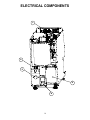
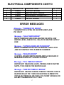
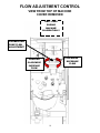
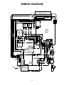
1
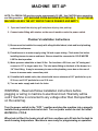
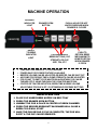
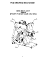
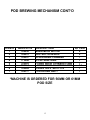
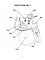
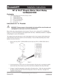
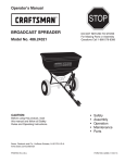
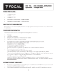
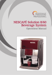
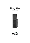
SINGLE SERVING AUTOMATIC POD MACHINE
NEWCO ENTERPRISES INC,
3650 NEW TOWN BLVD. SAINT CHARLES, MO 63301
1-800-325-7867 FAX 1-636-925-0029
Features/ Specifications
•
•
AUTOMATIC POD REMOVAL
LARGE POD WASTE TRAY / THRU COUNTER OPTION
• ADJUSTABLE DRINK STRENGTH
• ADJUSTABLE DRINK VOLUME
1
• 16 GRAM POD
CAPACITY
• REMOVABLE DRIP TRAY
TABLE OF CONTENTS
SPECIFICATIONS .......................................................................................................... 3
NEWCO PRODUCT WARRANTY .................................................................................. 4
MACHINE SET-UP......................................................................................................... 5
MACHINE OPERATION ................................................................................................. 6
MACHINE PROGRAMMING AND CALIBRATION......................................................... 7
SERVICING THE MACHINE ......................................................................................... 10
TANK REMOVAL ......................................................................................................... 11
POD BREWING MECHANISM ..................................................................................... 12
ELECTRICAL COMPONENTS ..................................................................................... 16
ERROR MESSAGES .................................................................................................... 17
FLOW ADJUSTMENT CONTROL ................................................................................ 18
WIRING DIAGRAM ....................................................................................................... 19
2
SPECIFICATIONS
TANK WATTAGES
US 1700W 120V- CANADA 1400W 120V- INTERNATIONAL 1700W 220V
TANK CAPACITY-1 US GALLON
DRIP TRAY CAPACITY 8 OUNCES
POD WASTE TRAY CAPACITY 80 PODS-USE WASTE TRAY
PN 780306 FOR THRU-COUNTER USE
UP TO 16 OZ CUP SIZE
SHIPPING WT-APPROX 35 LBS
3
NEWCO PRODUCT WARRANTY
Newco warrants equipment manufactured by it for 1 Year Parts & Labor
These warranty periods run from the date of installation Newco warrants that the equipment
manufactured by it will be commercially free of defects in material and workmanship existing at
the time of manufacture and appearing within the applicable warranty period. This warranty
does not apply to any equipment, component or part that was not manufactured by Newco or
that, in Newco’s judgment, has been affected by misuse, neglect, alteration, improper
installation or operation, improper maintenance or repair, damage or casualty. This warranty is
conditioned on the Buyer 1) giving Newco prompt notice of any claim to be made under this
warranty by telephone at (800) 556-3926 or by writing to PO Box 852, Saint Charles, MO 63302; 2)
if requested by Newco, shipping the defective equipment prepaid to an authorized Newco
service location; and 3) receiving prior authorization from Newco that the defective equipment is
under warranty.
THE FOREGOING WARRANTY IS EXCLUSIVE AND IS IN LIEU OF ANY OTHER WARRANTY,
WRITTEN OR ORAL, EXPRESS OR IMPLIED, INCLUDING, BUT NOT LIMITED TO, ANY IMPLIED
WARRANTY OF EITHER MERCHANTABILITY OR FITNESS FOR A PARTICULAR PURPOSE. The
agents, dealers or employees of Newco are not authorized to make modifications to this
warranty or to make additional warranties that are binding on Newco. Accordingly, statements
by such individuals, whether oral or written, do not constitute warranties and should not be
relied upon.
If Newco determines in its sole discretion that the equipment does not conform to the warranty,
Newco, at its exclusive option while the equipment is under warranty, shall either 1) provide at
no charge replacement parts and/or labor (during the applicable parts and labor warranty
periods specified above) to repair the defective components, provided that this repair is done by
a Newco Authorized Service Representative; or 2) shall replace the equipment or refund the
purchase price for the equipment.
THE BUYER’S REMEDY AGAINST NEWCO FOR THE BREACH OF ANY OBLIGATION ARISING
OUT OF THE SALE OF THIS EQUIPMENT, WHETHER DERIVED FROM WARRANTY OR
OTHERWISE, SHALL BE LIMITED, AT NEWCO’S SOLE OPTION AS SPECIFIED HEREIN, TO
REPAIR, REPLACEMENT OR REFUND.
In no event shall Newco be liable for any other damage or loss, including, but not limited to, lost
profits, lost sales, loss of use of equipment, claims of Buyer’s customers, cost of capital, cost of
down time, cost of substitute equipment, facilities or services, or any other special, incidental or
consequential damages.
4
MACHINE SET-UP
NOTE: The FRESH CUP machine weighs approximately 35 LBS. Use CAUTION when unpacking
and lifting machine. LIFT MACHINE FROM MACHINE BOTTOM ONLY. DO NOT MOVE
MACHINE UNLESS THE HOT WATER TANK IS DRAINED AND EMPTY.
1. Open and install the drip tray grill and place drip tray into pod tray
2. Connect water fitting with strainer on the rear of machine under the power switch.
Plumber's Installation Instructions
1) Brewer must be installed to comply with all applicable federal, state and local plumbing
codes and ordinances.
2) Plumb brewer in to water supply using 1/4 inch copper tubing. Flush water line before
installing brewer to remove sediment. Brewer should be connected to COLD WATER
LINE for best operation.
3) Water pressure should be at least 20 lbs. For less than a 25 ft run, use 1/4" tubing and
connect to 1/2" or larger water line. The inlet water fitting on the back of the brewer is a
1/4" flare fitting. It may be necessary to remove the plumbing cover box on the rear of
brewer to access water connection point.
4) If installed with saddle valve, the valve should have a minimum of 1/8" porthole for up to
25 ft run, and 5/16" porthole for over 25 ft runs.
5) Turn on water supply and check for leaks.
WARNING: - Read and follow installation instructions before
plugging or wiring in machine to electrical circuit. Warranty will be
void if machine is connected to any voltage other than that specified
on the serial tag.
Turn the power switch to the “OFF “ position and plug the machine into a properly
installed and grounded electrical circuit. Turn on power switch to start the initial
WATER FILL CYCLE.
When tank is filled, the heater circuit will turn on-allow up to 20 min for the tank to
reach brewing temperature. Machine is now ready for programming or operation.
5
MACHINE OPERATION
BREWING
INDICATOR
LIGHT
DRAWER OPEN
BUTTON
READY
TO BREW
INDICATOR
LIGHT
•
•
•
•
•
•
PUSH & HOLD FOR HOT
WATER DISPENSE WHEN
DRAWER IS CLOSED
PROGRAMMABLE
BREW BUTTONS (CUP
STRENGTH OR CUP
SIZE, TEA, ETC
PUSH TO
RETURN BREW
MECHANISM TO
HOME POSITION
WHEN DRAWER
IS OPEN
TEMPERATURE RANGE IS 170-205 DEGREES
POWER SAVE OR POWER FEATURE AVAILABLE
BEEPER VOLUME CAN BE ADJUSTED OR BEEPER CAN BE SHUT OFF
AIR PUMP POD DRYING TIME & PUMP STRENGTH CAN BE ADJUSTED
POD COUNT TO EMPTY POD WASTE BIN AJDUSTABLE OR CAN BE
TURNED OFF IF USING THROUGH THE COUNTER WASTE BIN
COFFEE OR TEA PRE-INFUSTION, BREW TIME & BREW VOLUME
ADJUSTABLE FOR EACH OF 3 CUSTOMIZABLE DISPENSE BUTTONS
BREW OPERATION
1.
2.
3.
4.
PLACE CUP UNDER BREW NOZZLE ON DRIP TRAY
PRESS THE DRAWER OPEN BUTTON
UNWRAP THE POD & PLACE IN CENTER OF BREW CHAMBER
PRESS THE DESIRED BREW BUTTON-DRAWER WILL CLOSE &
BREW CYCLE WILL START
5. ONCE THE POD DRYING CYCLE IS COMPLETE, THE POD WILL
EJECT & THE CUP CAN BE REMOVED
6
MACHINE PROGRAMMING AND CALIBRATION
NOTE: THE MACHINE HAS BEEN CALIBRATED AT THE FACTORY AND HAS BEEN ADJUSTED TO
BREW INTO AN 8 OUNCE CUP WITH APPROX 7 OUNCES OF COFFEE FOR BREW STRENGTHS OF
MILD, REGULAR AND BOLD. NO FURTHER ADJUSTMENTS ARE NECESSARY IF THE FACTORY
DEFAULTS ARE USED.
A
B
C
D
RESET
Fig 1: Fresh Cup Keys
The Fresh Cup pod brewer has a menu that consist of scrolling menu entries that can be
scanned through backward and forward using button A and button B (see Fig 1). To enter a
programming record, press and hold the Reset Key when powering up machine (see Fig 1) then
use button A and button B (see Fig 1) to change the entry. Pressing the Reset key (see Fig 1) will
exit the entry, saving the entire Parameter structure to memory upon exiting the programming
menu using the END entry. There are nine entries on the Main menu and four on one sub menu,
which is accessed through the BUTTON SET UP entry. The current entries in the Main menu
are as follows:
TEMPERATURE: In this entry the user may set the tank temperature in the range of 170 to 205
degrees Fahrenheit with the default at 200 degrees F. Pressing button D (see Fig 1) will toggle
the display so the user may view the real tank temperature. The real temperature display has all
three decimal points illuminated. Pressing button D (see Fig 1) again will switch the display back
to show the current set point. As with most of the entries, button A and button B (see Fig 1) will
change the set point, incrementing or decrementing by one. Pressing Reset key (see Fig 1) will
exit.
POWER SAVE: This entry allows the user to select the Power Save mode. Use button A and
button B (see Fig 1) to change the entry then press the Reset key to exit.
Off (default) – Turns Power Save function off.
Prt – Partial Power Save Mode. After the user selectable time out the tank temperature set
point is set to 180 until a key is pressed. When this mode is selected the right most decimal
point in the display is on.
FuL – Full Power Save Mode. After the user selectable time out the tank heater is disabled
until a key is pressed. When this mode is selected the left most decimal point in the display
is on.
POWER SAVE TIME: This entry will not be displayed if the Power Save function has been
turned off. This entry sets the time the machine will operate normally until the power save
function is activated. The user can choose 1 through 4 hours in 1-hour increments with the
default set to 4 hours. As with most of the entries, button A and button B (see Fig 1) will change
the time, incrementing or decrementing by one. Pressing Reset key (see Fig 1) will exit.
7
PROGRAMMING AND CALIBRATION CONT’D
BEEPER VOLUME: The range is from 1 to 24. The default is 13.
AIR PUMP SPEED: In this entry the user may set the air pump strength in the range of 5 to 10
strength with the default at 9. As with most of the entries button A and button B (see Fig 1) will
change the Air Pump Strength, incrementing or decrementing by one. Pressing Reset (see Fig 1)
key will exit.
AIR PUMP TIME: In this entry the user may set the air pump time in the range of 2 to 10
seconds with the default at 5. As with most of the entries button A and button B (see Fig 1) will
change the Air Pump Time, incrementing or decrementing by one. Pressing Reset (see Fig 1)
key will exit.
POD COUNT: In this entry the user may set the number of pods the brewer will hold before
signaling that the bin is full. The range is 10 to 100 pods, with the default at 40. Setting the pod
count under 10 turns off the count so the bin full alarm will never go off. As with most of the
entries button A and button B (see Fig 1) will change the Pod Count threshold, incrementing or
decrementing by one. Pressing Reset key (see Fig 1) will exit.
CALIBRATION: This entry shows the amount of water the brewer dispenses in 30 seconds
with no pauses. To run calibration, place a container able to hold at least 10 oz preferably
greater. Press button D (see Fig 1) and the brewer will enter a brew cycle. The door will open to
allow the user to place a beverage pod in the drawer. After the pod has been placed press the
button D button (see Fig 1) again to start the brew cycle. After the cycle has completed, measure
the amount of water dispensed and adjust the Calibration number shown in tenths of an ounce
to match the amount dispensed by using button A and button B (see Fig 1) to increment or
decrement by one. Press the Reset key (see Fig 1) to advance to the brew button programming
selections. Range for the calibration volume is 10 to 320 tenths of an ounce. The default is 100
tenths of an ounce.
BUTTON SET UP: This entry takes the user into a sub menu to program the parameters
unique to each key. When this entry is accessed the display will change to SELECT BUTTON
indicating that the user should press the brew key (button B, C or D (see Fig 1)) to be
programmed. When a brew key is selected the display will show the first entry in the Button Set
up sub menu, PRE-INFUSION. While SELECT BUTTON is displayed the user may exit back to the
Main menu by pressing the Reset key (see Fig 1).
With these four entries in the BUTTON SET UP sub menu:
PRE-INFUSION: This entry sets the time of the pre-infusion pulse of water in tenths of a
second. Range is 1 to 30, the default is 15 tenths of a seconds.
BREW VOLUME: This entry sets the volume in tenths of an ounce for this key to dispense.
The Range is from 40 to 140 tenths of an ounce with the default set to 70 tenths of an ounce
BREW TIME: This entry sets the brew time in seconds for a 10-ounce cup of coffee with
on/off pulses. The range is from 30 to 99 seconds with the default being 35 seconds.
RETURN: Exit to Main Programming Menu.
FILTER SELECT: This entry allows the user to select the filter size for the filter used on the
inlet for the water. Choices include OFF, 500 GAL, 1000 GAL and 1500 GAL. These set the
counter for the filter warning. Whenever water is dispensed the counter is incremented to
8
account for the water dispensed. When the counter is above 90% of the capacity of the chosen
filter a warning message, “REPLACE WATER FILTER”, is displayed in place of the “READY”
message. To reset the counter the user must enter the programming menu and enter the RESET
FILTER entry described below. The following entries are only shown when a filter is selected. If
the filter selection is OFF then following entries are not available. Press the Reset key (see Fig 1)
to leave the entry and return to the Main Programming menu.
FILTER REMAINING: This entry scrolls the number of Gallons left before the filter should be
replaced. Press the Reset key (see Fig 1) to leave the entry and return to the Main Programming
menu.
RESET FILTER: When in this entry the message “PRESS OPEN TO RESET’. Press the Open
Door key will reset the Filter Use counter to the value chosen in the FILTER SELECT entry
above. Press the Reset key (see Fig 1) to leave the entry and return to the Main Programming
menu.
END – Exit to Main and save parameters.
DRAINING THE HOT WATER TANK
THE DRAIN TUBE IS CLIPPED TO THE TANK PLATE IN FRONT OF THE TANK.
THE HOT WATER TANK CAN BE DRAINED FROM THE FRONT OF THE MACHINE –
UNPLUG MACHINE FROM POWER SOURCE . REMOVE POD WASTE TRAY.
CAUTION-UNLESS THE TANK IS LEFT TO COOL THE WATER IS EXTREMELY HOT
AND CAN CUASE HARMFUL BURNS. REPLACE DRAIN PLUG, ENSURE HOSE
CLAMP IS TIGHT AND REPOSITION DRAIN HOSE BEFORE RE-FILLING THE HOT
WATER TANK.
9
SERVICING THE MACHINE
The Fresh Cup machine has a modular Water Tank Assembly and Brew Mechanism.
These assemblies can be easily removed from the machine by removing or loosening
Machine nuts as noted in drawings below:
BREW MECHANISM
ACCESS SCREWS
(VIEW FROM BOTTOM FRONT OF MACHINE)
REMOVE
BRASS
KNURLED
NUTS
(2)
NOTE: TO REMOVE BREW
MECHANISM, UNSNAP
WATER & HARNESS
FITTINGS
LOOSEN
ACORN
NUTS
(4)
10
TANK REMOVAL
& TRANSFORMER ACCESS
REMOVE
(2) 8-32
NUTS
ON SIDE
WALL
REMOVE (1) 8-32 NUT
ON PUMP BRACKET
11
LOOSEN BUT DO NOT
REMOVE
THESE
2
SCREWS THEN LIFT &
PULL CONTROL BOARD &
BRACKET
OUT
OF
MACHINE TO ACCESS
TRANSFORMER
POD BREWING MECHANISM
BREW MECH ASS'Y
780234
(SPECIFY POD SIZE 56MM OR 61MM)
4
1
3
2
5
6
1
7
2
12
POD BREWING MECHANISM CONT’D
ITEM #
NEWCO PN
1
2
3
4
5
5
6
7
780230
780231
780257
773246
780262
780314
780264
780317
DESCRIPTION
BREW MECH MOTOR
DELTROL SOLENOID
UPPER BREW CHAMBER
U-CUP SEAL RING
LOWER BREW CHAMBER 61MM
LOWER BREW CHAMBER 56MM
O-RING .489 X .629 X .070
POD KICKER ASS’Y
QTY/EA
2
2
1
1
1*
1*
1
1
*MACHINE IS ORDERED FOR 56MM OR 61MM
POD SIZE
13
780234 TANK ASS’Y
10
1
2
9
3
8
7
6
4
5
14
780234 TANK ASS’Y CONT’D
ITEM #
NEWCO PN
1
2
3
4
5
6
7
8
9
10
110958
111593
706341
781772
780253
773056
108022
151677
110051
704166-10
DESCRIPTION
RELAY, 12 VDC SPST 30A
HI-LIMIT THERMOSTAT
PUMP ASS’Y-120 VOLT
PUMP ASS’Y W/ELBOW
PUNCHED TANK W/STUD
AIR PUMP, POD
LIQUID LEVEL PROBE
DUAL TEMP THERM PROBE
ELBOW ¼ TUBE X 1/8 NPT
TANK HEATING ELEMENT
15
QTY/EA
1
1
1
1
1
1
1
1
1
1
ELECTRICAL COMPONENTS
1
2
3
5
4
16
ELECTRICAL COMPONENTS CONT’D
ITEM #
NEWCO PN
1
2
3
4
5
780225
110626
780365
105115
780224
DESCRIPTION
CONTROL BOARD
SWITCH, DPST, ON/OFF
VALVE ASSY., FRESH CUP
TRANSFORMER 120VAC-24VAC
DISPLAY BOARD
QTY/EA
1
1
1
1
1
ERROR MESSAGES
Message - "THERMISTOR ERROR"
THERMISTOR IS OPEN OR SHORTED-REPLACE
PN 151677
Message - "HIGH TEMP ERROR"
RAPID TEMPERATURE RISE-HEATER ON WITH LOW
WATER LEVEL-CHECK FILL VALVE OR WATER SUPPLY
LINE
Message - "UPPER/LOWER MOTOR ERROR"
BREW CHAMBER DRIVE MOTOR ERROR-CHECK FOR
JAM OR OBSTRUCTION IN BREW CHAMBER
Message - "BOARD ERROR"
CONTROL BOARD WRITE ERROR-REPLACE BOARD IF
MESSAGE DOES NOT CLEAR PN 780225
Message - "FILL TIMEOUT ERROR"
WATER NOT REACHING LEVEL PROBE-CHECK WATER
SUPPLY OR CHECK FOR WATER LEAK
Message - "HEATER TIMEOUT ERROR"
WATER NOT HEATED DURING TIMEOUT PERIOD-CHECK
HEATER RELAY PN 110958 OR HEATING ELEMENT PN
704166-10(1700W US) OR 704161-10 (1400W CANADA) OR
HI-LIMIT THERMOSTAT PN 111593
17
FLOW ADJUSTMENT CONTROL
VIEW FROM TOP OF MACHINE
COVER REMOVED
ONLY USED
DURING
MACHINE
CALIBRATION ! !
CALIBRATION
PUMP FLOW
ADJUSTMENT
CLOCKWISE
DECREASE
FLOW
COUNTER
CLOCKWISE
INCREASE
FLOW
18
WIRING DIAGRAM
780225
SWITCH/DISPLAY BOARD
BK
RD
WASTE
BIN
REED
SWITCH
CN8
CN2
PROGRAMMING
HEADER
CN3
2
1
4
3
BK
CN1
RD
BK
RD
GY
LOWER
SOLENOID
UPPER
SOLENOID
12 VDC
12 VDC
BK
RD
CN6
2
1
GY
4
3
780224
24 VDC
BK
BR
YL
BK
WH
CONTROL
BOARD
UPPER
DRIVE
MOTOR
BK
RD
RD
BK
+-
RD
BL
CN7
7
6
5
4
3
2
1
RD
GY
-+
OR
BR
WH
GY
BK
BK/WH
BK
OR
AIR
PUMP
12 VDC
4321
321
RD
-
COFFEE
PUMP
120 VAC
8765
CN5
12 VDC
RD
BR
CN4
654
HOT +
WATER
PUMP
24 VDC
BK/WH
BK
GY
GY
LOWER
DRIVE
MOTOR
BR
CENTER
TAP
BK/WH
LEDs
+
12/24 VAC
BR
-
TRANS
FORMER
BK
GY
120 VAC
YL
RD
VIO/BK
RD
BK
14
13
12
11
10
9
8
BK
BK
WH
RD
DUAL
THERMISTOR
TANK
HEATER
ELEMENT
WH
HEATER RELAY
12 VDC
COIL +
GY
VIO/BK
VIO/BK
HI-LIMIT
THERMOSTAT
TANK
GND
LIQUID
LEVEL
PROBE
VIO/BK
DPST
SWITCH
VIO/WH
BK
WH
VIO/BK
HOT
WATER
TANK
GN
WH
FILL
SOLENOID
BK
120 VAC
WH
BK
POWER
CORD
19