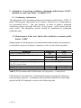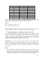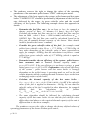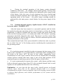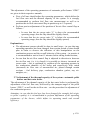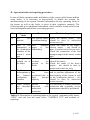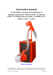
1
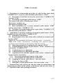
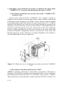
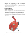
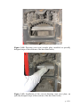
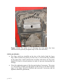
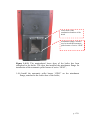
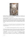
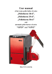
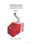
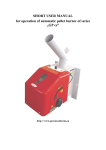
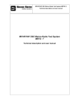
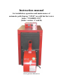
Instruction manual
for installation, operation and maintenance of
automatic pellet burner “GP45” on solid fuel hot water
boiler “VIADRUS U22”
(boiler version : C and D)
www.greenecotherm.eu
Producer
Address
Phone
Fax
e-mail
home page
ZMM Haskovo Plc.
Bulgaria, Haskovo 6300, “Saedinenie” 67 blvd.
+359 800 15 145
+359 38 603070
[email protected]
www.greenecotherm.eu
Thank You for buying our products – automatic pellet burner „GP45”
and burner’s installation kit. This manual will help You to install, use
and maintain the unit properly.
ATTENTION!
IN INTEREST OF YOUR PERSONAL SECURITY IT IS
NECESSARY TO READ THOROUGHLY AND CAREFULLY THIS
INSTRUCTION MANUAL BEFORE PROCEEDING WITH ANY
ACTIONS WITH THE BURNER – INSTALLATING, CONNECTING,
OPERATING, ETC. IN CASE THAT REQUIREMENTS, DEPICTED IN
THIS MANUAL ARE NOT SATISFIED, FAILURE OF THE UNIT
COULD BE EXPECTED, OR EVEN FATAL CONSEQUENCES, FOR
WHICH
PRODUCER
COMPANY
DOES
NOT
TAKE
RESPONSIBILITY.
• According to Bulgarian government decree “МС № 187/21.09.2000” the
boiler “VIADRUS U22” should be treated as high risk equipment and
should be reported by the end user to the regional technical supervision
register;
• In interest of your personal security it is necessary to read thoroughly and
carefully this instruction manual before proceeding with any actions with
the burner as well as with the boiler – installation, connecting, adjustment,
servicing, etc. in case that requirements, depicted in this manual are not
satisfied, failure of the unit could be expected, or even fatal consequences,
for which the producer company does not take responsibility;
Instruction manual for installation, operation and maintenance of automatic pellet burner
“GP45” on solid fuel hot water boiler “VIADRUS U22” (Version : 31.03.2011 13:55)
p. 2/31
Table of contents
page
1. Description of reconstruction procedure of solid fuel hot water boiler
“VIADRUS U22” to operate with automatic pellet burner “GP45”.............. 4
1.1. Description of solid fuel cast iron hot water boiler “VIADRUS U22”
(version C or D)................................................................................................ 4
1.2. Description of automatic pellet burner “GP45”................................. 4
The burner could utilize following types of fuel ........................................... 5
The burner’s modules are ............................................................................... 5
The burner is equipped with........................................................................... 6
1.3. Basic information for a system: automatic pellet burner “GP45”
and hot water boiler “VIADRUS U 22” ........................................................ 7
1.4. Procedure for reconstruction of hot water boiler “VIADRUS U 22”
with automatic pellet burner “GP45”............................................................ 7
2. Adjustment of operating conditions of automatic pellet burner “GP45”,
installed on a hot water boiler “VIADRUS U22”........................................... 20
2.1. Preliminary information ..................................................................... 20
2.2. Requirements of the fuel, which will be utilized by automatic pellet
burner “GP45” ............................................................................................... 20
Table 2.2.1. Recommended solid biomass fuel properties – wood pellets..... 20
Table 2.2.2. Pellets classification, considering their physical properties
according to the methodology developed by ERATO company..................... 21
2.3. Operating parameters of automatic pellet burner “GP45” ............ 21
2.4. Nominal thermal capacity of pellet burner “GP45”, installed on hot
water boiler “VIADRUS U22”...................................................................... 23
2.5. Combustion process adjustment ........................................................ 24
2.6. Combustion process adjustment algorithm ...................................... 26
2.7. Adjustment of the thermal capacity of the system : automatic pellet
burner and hot water boiler.......................................................................... 27
2.7.1. Decreasing the thermal capacity of the boiler ........................... 28
2.7.2. Increasing the thermal capacity of the boiler ............................ 28
2.8. Stopping the system : pellet burner + hot water boiler ................... 28
2.9. Turning the burner OFF..................................................................... 28
• Emergency system (pellet burner + hot water boiler ) stop ............ 29
3. Demonstrating and teaching the end user about the maintenance and
adjustment procedures of the system : pellet burner and hot water boiler 29
4. Operation faults and repairing procedures ............................................. 31
p. 3/31
1. Description of reconstruction procedure of solid fuel hot water boiler
“VIADRUS U22” to operate with automatic pellet burner “GP45”
1.1. Description of solid fuel cast iron hot water boiler “VIADRUS U22”
(version C or D)
The hot water solid fuel boiler “VIADRUS U 22” (version C and D) is
designed to be connected in local heating systems, which could be realized both
with gravity driven circulation of the fluid as well as forced circulation, applied
by circulating pump. The boiler consists of n-cast iron sections (n=4…10) and is
designed to be manually fuel (coal or wood) charged through an opening in the
upper part of the front section, closed by a cast iron door. Ash residue removal is
manually realized through the lower door of the boiler as well. The combustion
process is highly optimized due to the specific design of the boiler’s grate and
combustion chamber configuration. However the operation of the boiler (the
thermal capacity as well as efficiency) is strongly dependant of the chimney’s
natural draught and the flue gas temperature.
Figure 1.1.1. Explosion view of solid fuel cast iron hot water boiler“VIADRUS
U22”.
1.2. Description of automatic pellet burner “GP45”
“GP45” is automatic pellet burner, which utilizes wood pellets. The burner is
designed to be installed on already operating heating boilers or other equipment,
thus allowing fuel switch procedure to a renewable energy sources - biomass.
The heating boiler or heat consumer could be based on fossil fuel as follows: oil,
p. 4/31
gas, wood, coal, etc. The installed burner operates on densified fuel - wood
pellets and the thermal energy, resulting from the intensive combustion process
is directed to the heat exchange surfaces of a boiler or another thermal
consumer. The wood pellets allow high level of automation of the operating
process of such kind of equipment, thus achieving high level of comfort and
competitive price of the heating energy, delivered by utilizing biomass fuel.
However, the wood pellets are solid fuel as well and ash residue results from the
combustion process, realized by the automatic burner, due to their natural ash
content. In principal the ash residue quantity is much less compared to the coal
or wood logs. The ash residue is deposited on the internal surfaces of the boiler
and need manual cleaning regularly in order to sustain high heat exchange
intensity between the hot flue gases and the water jacket of the boiler. The
operation of automatic pellet burner “GP45” corresponds to the functionality of
an automatic unit, which utilizes common energy source – oil, gas, electricity
for example. However, the price of the achieved heat energy is competitive to
the price of the above mentioned energy sources as well as the wood pellets are
local product, less influences by the world trends of energy sources prices and is
ecological and environmentally friendly.
The burner could utilize following types of fuel
• Wood pellets, complying the requirements of ENplus-A1, having
diameter 6 and 8 mm, also categorized in the range of: A, AB, B
(according to the methodology, developed for pellets properties
estimation in ERATO company);
• Pre-dried pits (cherries for example);
• Fuel mixture – pellets and pits (for example mixture ratio could be 50% 50%);
• Other solid biomass based pellets, but these fuels need testing and
approval in ERATO company laboratory;
The burner’s modules are
• adjustable operating module, which controls the functions of the unit and
is adjustable to the specific needs of a heating system;
• auger, which transports fuel from a bunker to the main unit;
• fresh air supplying fan, equipped with a Hall sensor, which returns
information to the control unit;
• electric heater, which ignites the fuel;
• combustion chamber, which gives environment for efficient combustion
process;
• removable grate of the combustion chamber, allowing easy access and ash
cleaning;
p. 5/31
• photosensor, which gives information for the status of the combustion
process to the control unit and allows dynamic operation of the burner;
• interface panel, equipped with light indicators;
• the control board is equipped with led indicator for indicating the status of
adjustable parameters index value;
• a variable potentiometer, which allows easy thermal capacity adjustment;
The burner is equipped with
• automatic fuel ignition system;
• automatic fuel transport system – from bunker to the combustion chamber
of the main unit;
• safety system, which blocks its operation in case that at any circumstances
the fuel delivery pipe is preheated above certain temperature safety level;
• photosensor, which allows dynamic monitoring of the combustion process
status;
• process control system, which modulated the air supply fan operation at
ignition process;
Figure 1.2.1. Side view of automatic pellet burner “GP45”.
p. 6/31
1.3. Basic information for a system: automatic pellet burner “GP45” and
hot water boiler “VIADRUS U 22”
The automatic pellet burner “GP45” is mounted on a transformed (redesigned)
lower door of the boiler, utilizing attachment flange. However, in order to
achieve high intensity of the heat exchange rate between the flue gases and the
surface of the boiler, it is necessary to install a transition kit – a kit of specially
designed directing elements.
The achieved thermal capacity of the system : automatic pellet burner
“GP45” and the cast iron hot water boiler depends on:
• number of sections of the boiler and its nominal thermal capacity;
• the range of the ash contamination and the resulting thermal resistance of
the ash deposits layer;
• the air tightness of the boiler’s doors (i.e. the condition of the thermal
resistant ropes);
• chimney’s draught and position of the flap at the flue gases exit of the
boiler;
The effective efficiency of a system : automatic pellet burner “GP45” and a hot
water boiler “VIADRUS U22” at nominal thermal load reached 82% for a 7
section boiler - this is achieved by adjustment of the operating parameters of the
combustion process (performed by specialist). The efficiency is affected by the
number of the sections of the boiler as well as the ash deposition and the overall
condition of the boiler. The practice shows that at increased number of sections
the efficiency of the systems is increasing as well;
1.4. Procedure for reconstruction of hot water boiler “VIADRUS U 22”
with automatic pellet burner “GP45”
1.4.1. Clean thoroughly the internal heat exchanging surfaces of the boiler
– clean ash residue, char and tar deposits, which could increase the
thermal resistance of the surfaces and reduce the overall efficiency of
the boiler;
p. 7/31
Nuts, fixing the
lower door’s
knuckle the boiler
Figure 1.4.1. Front view of hot water boiler “VIADRUS U22” (version
C) with both doors opened;
1.4.2. Take away the triangle shaped grate, positioned in the lower door
of the boiler;
Figure 1.4.2. The triangle shaped grate is taken away;
p. 8/31
1.4.3. Detach the lower door of the boiler by unscrewing the fixing nuts
of the door to the heat exchanger;
In case the lower door has not been processed before the automatic pellet
burner installation, than it has to be detached and an orifice should be
made. Then the burner will be attached on the door, by using the
attachment flange, applied in the kit of the pellet burner. This attachment
flange should be installed on the door, but the fixing bolts should be left
uptight (loosened), which will allow easy installation of the pellet burner,
by using bolts M8. The following figure shows a chart, which should used
in order to transform the door of the boiler in order to run on wood pellets
as fuel. After the door has been manipulated and the orifice for the flue
gases of the burner has been made, the attachment flange should be
installed.
RECOMENDATION : the orifices for the fixing of the bolts, which will
be used to fix the attachment flange of the burner should be made “on
site”, i.e. when the position of the attachment flange is clarified and the
orifice for the burner’s head is made;
EXPLANATIONS :
• The flap for the primary air, installed on the lower door of the boiler
should be fixed at closed position, as well as the flap, which is installed on
the upper door (also fixed closed);
• The tightening ropes, which are installed on the doors should be checked
and replaced if necessary. In case of uptightness, special care should be
taken in order to ensure the proper operation of the boiler (flue tightness);
p. 9/31
35
4xМ8
140
Orifice for the flue gases
210
195
163
Primary air flap (should be
fixed at closed position)
Figure 1.4.3. Chart for manufacturing the lower door of the hot water
boiler “VIADRUS U22” – front side view;
p. 10/31
Figure 1.4.4. Front side view of the lower door of the hot water boiler of
series “VIADRUS U22” has been manipulated in order to operate with
burner of series “GP45”;
1.4.4. Install the attachment flange of the pellet burner of series “GP45”
on the lower door of the boiler.
Explanation : the attachment flange should be tightened only after the
burner has been installed, then all the fixing bolts and nuts should be
tightened in order to ensure stable and reliable installation of the pellet
burner to the hot water boiler’s door;
p. 11/31
Figure 1.4.5. Attachment flange and the automatic pellet burner of series
“GP45”;
1.4.5. Position the applied directing plates (so called “straight” and
“curved” cast iron plates), which should be arranged close to each
other on a intentionally produced internal steps at the internal surface
of the combustion chamber of the boiler. These plates allow multitract flue gas dynamics in the combustion chamber and increase the
overall efficiency of the system – hot water boiler “VIADRUS U22”
and the automatic pellet burner.
Attention : the installation of the above mentioned directing plates is
obligatory, their appropriate and correct arrangement will allow high
efficiency and reliable operation of the automatic pellet burner “GP45”,
installed on the hot water boiler “VIARDUS U22”;
p. 12/31
Figure 1.4.6. Principal arrangement (the distance between the plates is
intentionally in order to show their arrangement on the picture) of
directing plates, which are mounted in the combustion chamber of the
boiler;
Explanation:
• The directing plates are parts of the kit for hot water boiler’s
reconstruction, which allows fuel switch to wood pellets and
automatic performance of the heating unit;
• The number (count) of the so called “straight” plates, which should
be installed in the combustion chamber of the boiler depend on the
number of boiler’s sections. Additional information is given in
Table 1.4.1.;
• The arrangement of the directing plates should be made in
appropriate order – start with installing (over the special steps of
the sections of the boiler) the most internal straight directing plate
and continue in direction out of the combustion chamber of the
boiler. The last directing plate is the so called curved one and all
the plates should be finally arranged close to each other in order to
ensure separate volumes of the combustion chamber;
p. 13/31
Number of
the sections
of the boiler
6
7
8
9
10
Number of
“curved”
plates
1
1
1
1
1
Number of
“straight”
plates
3
4
5
6
7
Table 1.4.1. Information for the number of required directing plates,
which should be installed in the combustion chamber of the hot water
boiler “VIADRUS U22”.
Figure 1.4.7. Directing (cast iron) straight plate, installed on specially
designed steps of the sections of the hot water boiler (only the first plate is
installed);
p. 14/31
Figure 1.4.8. Directing (cast iron) straight plate, installed on specially
designed steps of the sections of the hot water boiler;
Figure 1.4.9. Installation of the curved directing (cast iron) plate, on
specially designed steps of the sections of the hot water boiler;
p. 15/31
Figure 1.4.10. The entire set of directing cast iron plates has been
installed on the specially designed steps of the cast iron boiler;
EXPLANATIONS :
• The flaps, which are installed on the door of the boiler (both the lower
flap, which controls the primary air flow rate, as well as the flap, installed
on the upper door, which controls the secondary and tertiary air flow rate)
should be fixed at closed position in order to prevent uncontrolled air
leakage;
• Check the tightening ropes of the door and replace if necessary. The status
(i.e. their ability to make air tight gasket of the doors) of the heat resistant
ropes of the doors should be checked and renewed if necessary and air
tightness should be guaranteed;
p. 16/31
Lower door of the
combustion chamber of the
boierl
Attachment flange, which is
used to install the automatic
pellet burner of series “GP45”
Figure 1.4.11. The manipulated lower door of the boiler has been
reattached to the boiler. The door has installed the attachment flange for
installation of the automatic pellet burner of series “GP45”;
1.4.6. Install the automatic pellet burner “GP45” on the attachment
flange, attached to the lower door of the boiler;
p. 17/31
Figure 1.4.12. The automatic pellet burner of series “GP45” is installed on the
lower door of the cast iron hot water boiler “VIADRUS U22” (view from the
internal side of the doors of the boiler);
EXPLANATION : the pellet burner of series “GP45” is installed in such a way,
that its frontal surface should be leveled with the surface of door at the internal
side of the door. Such an installation approach allows reliable and optimal
operation of the burner and the entire system, as well as high intensity of the hot
flue gases, emitted from the burner’s head to the combustion chamber of the
boiler;
The producer reserves the right to change the specification and/or the design of
the transition kit, which allows installation of automatic pellet burner “GP45”
without prior notice;
1.4.7. Connection of automatic pellet burner “GP45” to the power supply;
The burner should be connected to the power supply and the appropriate safety
rules should be satisfied. Follow the instructions, described in automatic pellet
burner’s manual. The connection should be done by authorized technician only.
ATTENTION : the boiler should be equipped with operating and alarm
thermostat (or a combination in a single module – so called bi-thermostat),
which controls the operation of the burner, following the electrical scheme,
p. 18/31
applied in its manual. Explanation: These thermostats are not part of the
transition kit for installing the automatic pellet burner “GP45” and should be
delivered and installed by authorized technician.
1.4.8. Install the fuel transport auger, which feed the burner, extracting
fuel from a bunker. Follow the instructions, depicted in the burner’s
manual;
The fuel transport auger should be properly installed and should allow fuel
transport without difficulties and obstacles. The fuel should be extracted from
the lowest part of the bunker. In case that the bunker is made on site, then a so
called revision orifice should be made in order to allow easy service and
maintenance of the auger. The auger’s external pipe should be properly
positioned and fixed in order to sustain reliable fuel transport.
Explanation : the angle between the axis of the fuel transport auger and the
horizontal plane directly influence the fuel flow rate, delivered by the auger.
Thus in case that the position of the auger has been changed (i.e. the above
mentioned angle has been changed) a new adjustment of the operating
parameters of the burner could be required in order to achieve high efficiency of
the burner and its reliable functionality;
1.4.9. Connection of the fuel transport auger to the main unit of automatic
pellet burner “GP45”;
Connect the fuel transport auger to the main unit of the automatic pellet burner
“GP45” according to the instructions, depicted in the burner’s manual.
Explanations:
• The producer reserves the right to change the design of the transition kit,
which allows installation of automatic pellet burner “GP45” on a hot
water boiler “VIADRUS U22” without prior notice;
• Prior to initial startup of the burner as well as in case that the fuel in
bunker has been totally consumed, then the auger should be refilled with
fuel – the procedure is described in details in the burner’s manual. The
auger’s fuel refilling procedure should be explained and demonstrated to
the client/maintenance personal of the system : pellet burner – hot water
boiler;
p. 19/31
2. Adjustment of operating conditions of automatic pellet burner “GP45”,
installed on a hot water boiler “VIADRUS U22”
2.1. Preliminary information
The adjustment of the operating parameters of automatic pellet burner “GP45” is
made, following the instructions in the burner’s manual. It is recommended to
use specialized device – flue gas analyzer, in order to achieve optimized
combustion process and high efficiency of the system – pellet burner and hot
water boiler. The adjustment process should be performed by authorized
technician only.
2.2. Requirements of the fuel, which will be utilized by automatic pellet
burner “GP45”
Requirements for the properties of recommended solid biomass fuel properties –
wood pellets, are given in burner’s manual as well as in the following tables.
Parameter
Pellet’s characteristic size
Recommended fuel net calorific value
Wood pellet class according to ENplus
Wood pellets category, according to
ERATO classification
Ash content
Moisture content
Dimension
Value
mm
6–8
MJ/kg
>17.2
kWh/kg
>4.7
ENplus- A1
A, AB, B
%
%
See Table 2.2.2
Max. 8 – 10%
Table 2.2.1. Recommended solid biomass fuel properties – wood pellets.
Classification of wood pellets, considering their physical properties (based on
fuel proximate analysis) – according to fuel evaluation method, developed and
applied in ERATO company is show on the following table.
p. 20/31
Pellet’s category
A
AB
B
BC
C
CD
D
DE
E
EF
Ad
A ≤ 0.6%
A d ≤ 0.6%
0.6 < A d ≤ 1.0%
0.6 < A d ≤ 1.0%
1.0% < A d ≤ 2.0%
1.0% < A d ≤ 2.0%
2.0% < A d ≤ 3.0%
2.0% < A d ≤ 3.0%
A d > 3.0%
A d > 3.0%
d
DU
DU
DU
DU
DU
DU
DU
DU
DU
DU
DU
≥ 97.0%
< 97.0%
≥ 97.0%
< 97.0%
≥ 97.0%
< 97.0%
≥ 97.0%
< 97.0%
≥ 97.0%
< 97.0%
Table 2.2.2. Pellets classification, considering their physical properties
according to the methodology developed by ERATO company.
where :
Ad – ash contents, dry basis, [%];
DU – mechanical durability, [%];
EXPLANATION : detailed information about the requirements for the wood
pellets according to ENplus norm is given in the pellet burner’s manual.
2.3. Operating parameters of automatic pellet burner “GP45”
The operating parameters of automatic pellet burner “GP45” are given in the
burner’s user manual. These parameters determine the operating mode of the
burner, i.e. the system: burner-boiler. These parameters – their meaning and
adjustment procedure should be explained to the end user/client in order to allow
flexible operation and optimal performance of the system.
Explanation: Any variation of the operating parameter’s values should be done
only in case that the operating algorithm, the physical meaning of the
parameters and their influence on the performance of the burner are known for
sure. It is recommended to adjust the operation parameters by authorized
personal only.
Notes :
•
The corresponding requirements, defined in the user manuals of the units of
the system : burner-boiler contain operating parameters and requirements,
which should be satisfied in order to achieve required thermal capacity, high
efficiency and reliable operation of the system and the units in particular;
p. 21/31
•
The producer reserves the right to change the values of the operating
parameters of the automatic pellet burner “GP45” without prior notice
•
The adjustment of the heat capacity the system: pellet burner and hot water
boiler “VIADRUS U22” should be performed by adjustment of the fuel flow
rate, delivered by the auger, its gross calorific value and the overall
efficiency of the system. The following example shows this approach in
details:
o Determine the fuel flow rate ( for an hour or less, for example a
shorter period of time– 15 minutes=1/4 hour)- mfuel=9.4 kg/h.
Calculate the instant fuel flow rate (m’fuel), (divide fuel flow rate per
hour on 3600 , where 1 hour = 3600 seconds) and achieve m’fuel =
0.002611 kg/s. The fuel flow rate could be calculated, based on its
flow rate at nominal thermal capacity of the burner. More details
could be found in the burner’s manual;
o Consider the gross calorific value of the fuel– for example wood
pellets have calorific value Hpellets = 17.2 MJ/kg = 17200 kJ/kg. In
case other dimension of the calorific value is more convenient to
apply, for example – kWh/kg, then the calculation is as follows : wood
pellets have gross calorific value of 4.77 kWh/kg (which is equal to
17.2 MJ/kg);
o Determine/consider the net efficiency of the system : pellet burnerhear consumer unit at nominal thermal capacity mode –
ηsystem=82%=0.82. If the net efficiency is not know a priory, a good
initial guess is ηsystem=85%=0.85. Explanation : the overall efficiency
of the system : pellet burner and hot water boiler is strongly
dependant on the pellet burner’s operating mode as well as the ash
residue deposits and the resulting thermal resistance layer on the heat
exchanging surfaces of the boiler;
o Calculate the thermal capacity of the hot water boiler Pboiler = η system * H pellets * m' fuel = 0.82 *17200 * 0.00261 = 36.8 kW if the calorific
value of the fuel is applied in dimension – MJ/kg. In case that the
calorific value of the fuel is applied in other dimension, for example
kWh/kg,
then
the
calculation
is
as
follows
Pboiler = η system * H pellets * m' fuel = 0.82 * 4.77 * 9.4 = 36.8 kW;
o The same algorithm should be followed for calculating thermal
capacity of the hot water boiler in case that the fuel calorific value
differs that cited above or the required thermal capacity of the unit is
different that in the above example;
The producer reserves the right to change the factory defined values of
operating parameters of the burner without prior notice;
p. 22/31
•
During the nominal operation of the burner certain abnormal
conditions could arise – for example unsuccessful ignition, fuel has been
consumed, etc, some of these conditions are indicated on the control board
of the burner. After the cause of such situations have been clarified and
certain precaution measures have been taken, it is necessary or reset the
operating mode of the burner – the pellet burner resetting should be
performed by the main power circuit breaker for the power supply of the
boiler;
2.4. Nominal thermal capacity of pellet burner “GP45”, installed on
hot water boiler “VIADRUS U22”
After the burner has been started (i.e. successful ignition) and the boiler
has reached steady-state operation mode (it is heated-up) as well as the heating
installation, it could be assumed that the entire system (the pellet burner, the
boiler and the heating system) is in steady-state mode. The burner’s operating
parameters should be adjusted in this mode. The burner’s air flow control flap
should be adjusted as well in order to achieve efficient combustion process and
optimal performance of the system.
The nominal thermal load of the system should be utilized on order to perform
the so called “hot test” of the heating system, considering the requirements of
the governing norms.
Notes:
•
If a circulating pump is installed in order to transport the heat energy of the
boiler to the consumers, it is recommended to control the inflow temperature to
the boiler to be above 60oC. In case of low inflow temperature level,
condensation of water vapor could be observed on the internal heat exchanging
surfaces (please consider that water vapor is one of the final products of the
combustion process and always persist in the flue gases of the boiler);
•
It is not recommended to operate the system : pellet burner and hot water
boiler at thermal capacity lower than 50% of its nominal thermal load, as such
regimes are not optimal and thus have low efficiency;
Explanation : in case that the hot water boiler should operate at thermal
capacity lower than 50% of the nominal thermal load, it is strongly
recommended to install a heat accumulator tank in the heating system in order
to achieve high efficiency and reliable performance of the system and the
installation;
p. 23/31
• During the very first time of operation the boiler it is possible to observe
water vapor condensation on the heat exchanging surfaces of the unit.
Practically this is one-time process and will not affect the performance of the
unit, neither any problems will arise as well;
•
It is strongly forbidden to operate the automatic pellet burner “GP45” at
thermal capacity, which are above the nominal thermal capacity of the burner or
the boiler (whichever has lower value). In case that this requirement is not
fulfilled certain thermal damages could arise both at the combustion chamber of
the burner or overheating of the heat exchanger of the boiler. These modes are
not governed by the warranty of the units and are not recognized by the unit’s
producers/suppliers;
2.5. Combustion process adjustment
The operating parameters adjustment should be performed by authorized
trained technician, considering the governing norm’s requirements for such type
of equipment. The adjustment of operating parameters should be performed at
nominal thermal capacity, i.e. the system is in steady-state and no major
parameter’s fluctuations are observed (for example variation of the circulating
fluid temperature, etc). The adjustment of the thermal capacity of the burner is
realized by adjustment of the fuel flow rate as well as the air flow rate in order
to achieve high efficiency.
In principal air excess ratio influence could be observed on figure 2.5.1. The
optimal value of air excess ratio is achieved by precise adjustment of the air
flow control flap as well as fuel flow rate. However, the practice shows that
there are certain variations of the fuel characteristics and its quality in general,
as well as the chimney’s draughts, which require individual adjustment of the
system: pellet burner and hot water boiler, installed in a heating system. The
chimney’s draught of the hot water boiler “VIADRUS U22” could be adjusted
by turning the flue gas flow rate control flap, installed on the boiler’s flue gas
exit, considering the recommended operating parameters of the boiler, as well as
ensuring reliable operating conditions for the pellet burner “GP45”. However,
one should consider operating conditions of the burner in order to achieve safe
operation of the burner – there should be no hot flue gases convection through
the fuel delivery pipe – this should be achieved by mutual adjustment of the fuel
flow rate, air flow rate and position of the flue gas flap.
The combustion process adjustment should be realized, covering the flue gases
requirements, according to EN 303-5 – see table 2.5.1 for details.
The following table (a passage) consists of the upper limits of the flue gas
pollutants, defined by EN 303-5:
p. 24/31
Nominal thermal
capacity
kW
≤50
>50 до 150
>150 до 300
Flue gas pollutant species concentration limits
CO
OGC
Ash
3
mg/m at 10% О2 *
3000
2500
1200
100
80
80
150
150
150
Table 2.5.1. A passage of norm EN 303-5 about the flue gases pollutant species
limits;
* the above values are based/calculated on 10% oxygen volume fraction (O2) in
the flue gases and are calculated on the basis of following conditions : absolute
pressure 101325 Pa (1013 mbar) and temperature 0оС;
where :
CO – carbon monoxide mass fraction in the flue gases, [mg/m3 at 10% О2];
OGC – organic compound mass fraction in the flue gases (chemically bound
carbon) , [mg/m3 at 10% О2];
Ash – mineral matter mass fraction in the flue gases, [mg/m3 at 10% О2];
Attention : The air flow rate strongly influences the efficiency of the combustion
process and the overall performance of the burner – in case that the air flow
rate is below certain optimal value, then partially unburned fuel will be
observed, which will result in decreased efficiency. However, in case that the air
flow rate is above certain optimal value, the air excess will result in decrease of
the temperature in the zone of the combustion process, which will lead to
decreased efficiency of the combustion process and partially unburned fuel as
well. The optimal air flow quantity is determined by flue gas measurement and
individual adjustment of the operating parameters of the system : pellet burner
and boiler’s draught. The recommended value of air excess ratio is given in the
pellet burner specifications, however the flue gases limits requirements should
be satisfied as well – the flue gas measurements are performed by gas analyzer
device.
Explanation : as a rule of thumb – the air excess ratio – “λ” should be as low
value as possible, but in any case its value should be above 1.0 and the resulting
efficiency of the combustion process will be higher and the overall efficiency of
the system : automatic pellet burner and hot water boiler, will be as higher as
possible. The adjustment of the combustion process will be influenced by the
following factors, which should be considered:
p. 25/31
•
•
Ambient temperature;
Parameters of the environment (mainly temperature, pressure, relative
humidity );
Dimensions of the chimney, as well as the hydraulic pressure losses,
which determine its draught;
Access of the air of the environment to the room, where the system :
burner and the boiler are installed;
Other special features – any flue gas leakages of door’s gasket of the
combustion chamber for example;
•
•
•
CO , [mg/m3]
λ
λmin
Range of minimal values of
Диапазон
CO
fractionнаinоптимална
the flue gases.
стойност на коефициента
на излишък на въздух λ
λmax
λ , [mg/m3]
CO
Range of optimal value of air excess ratio, which allows high
efficiency of the combustion process
Figure 2.5.1. Characteristic function of CO mass fraction in the flue gases
and the air excess ratio – λ;
The above information shows that low values of air excess ratio results in
increased CO mass fraction in the flue gases – the process is explained with
inefficient mixing of the air flow and the combustible gases of the fuel. In
practice it is possible such kind of combustion process (low air excess ratio and
high amount of CO and unburned hydrocarbons) to result in char residue
deposits on the heat exchanging surfaces, which will result in decreased
efficiency of the system : pellet burner + hot water boiler. However, increased
air flow rate (i.e. the air excess ratio is above the optimal range) will result in
increased CO mass fraction in the flue gases due to increased cooling effect of
the fresh (and relatively cool) air on the combustion process, despite the
increased turbulent intensity and intensified mixing process. The above
mentioned shows that precise adjustment of the operating parameters, which
define the combustion process, should be performed by authorized and trained
technician by flue gas measurement, utilizing gas analyzer.
2.6. Combustion process adjustment algorithm
p. 26/31
The adjustment of the operating parameters of automatic pellet burner “GP45”
are given in their respective manuals.
• First of all one should adjust the operating parameters, which define the
fuel flow rate and the thermal capacity of the system. It is strongly
recommended to perform fuel flow rate measurement as well as to
position the air flow rate control flap in position up to 1/2 opened;
• Perform precise adjustment of the position of the air flow control flap as
follows :
o In case that the air excess ratio “λ” is above the recommended
operating range, then the flap should be slightly closed;
o In case that the air excess ratio “λ” is below the recommended
operating range, then the flap should be slightly opened;
Explanations :
• The adjustment process should be done in small steps : in case that any
operating parameter has been changed, then certain period of time should
pass in order to observe the influence of this manipulation on the
combustion process and the overall behavior of the system – in practice it
is recommended to wait at least 15 minutes before taking further actions;
• In case that the air flow control flap is adjusted in direction to decrease
the air flow rate (i.e. it is closed) it is possible to observe increased air
excess ratio – this is explained by variation of the operating pressure in
the combustion chamber of the boiler and respectively with varied
(increased) air flow rate of uncontrolled air, passed through certain
sections – fuel delivery pipe, combustion chamber gasket, any airuntights, etc.;
2.7. Adjustment of the thermal capacity of the system : automatic pellet
burner and hot water boiler
The adjustment of the thermal capacity of the hot water boiler is performed by
adjustment of the fuel flow rate, delivered by the transport auger of the pellet
burner “GP45”, as well as the air flow rate – see the procedure for adjustment of
the combustion process.
Attention : in case that the fuel type has been changed (for example fuel origin,
or pellet’s quality) it is recommended to perform adjustment of the operating
parameters of the burner, which define its operating mode and overall
efficiency.
p. 27/31
2.7.1. Decreasing the thermal capacity of the boiler
It is performed by decreasing the operating parameters of the burner,
which define its thermal capacity and will result in decreased fuel flow
rate;
2.7.2. Increasing the thermal capacity of the boiler
It is performed by increasing the operating parameters of the burner,
which define its thermal capacity and will result in increased fuel flow
rate;
Explanation : in case that the thermal capacity of the burner is varied in
wide range (exceeding 20% of the operating mode), then it is
recommended to perform air flow rate adjustment. Decreasing the air
flow rate is performed by closing the air control flap, in reverse –
increasing the air flow rate is performed by opening the air flow control
flap;
Attention : adjustment of the operating parameters, which define the thermal
capacity of the burner should be performed by authorized technician or trained
end user, in order to achieve optimal combustion process and reliable operation
of the system. It is recommended to utilize gas-analyzer when adjusting the
operating parameters of the combustion process;
2.8. Stopping the system : pellet burner + hot water boiler
Stopping the operation of the system should be performed by stopping the
operation of the pellet burner. For more information refer for the appropriate
procedure in the burner’s manual.
ATTENTION : In case that the burner/boiler will not operate for a long period
of time, then thorough ash deposit cleaning procedure should be performed. The
ash layer acts corrosively on the carbon steel surfaces, which will lead to a
decrease of the lifetime of the burner’s main module. It is obligatory to perform
service procedures and preventive observations of the unit by trained service
personal only as well as thorough cleaning at the end of the heating season.
Completing these requirements will ensure long exploitation duration of the
system: pellet burner and hot water boiler and their high efficiency and
reliability.
2.9. Turning the burner OFF
The pellet burner “GP45” is turned off, following the detailed procedure,
described in their respective manuals. After the burner has been cooled down to
ambient temperature, it should be switched off by turning off the main power
p. 28/31
supply. It is recommended to clean the deposited ash thoroughly both of the
burner as well as hot water boiler heat exchanging surfaces.
• Emergency system (pellet burner + hot water boiler ) stop
In operating process of the pellet burner “GP45” emergency situations
could arise and the unit will go into alarm/failure mode. Such situations are
detected by the process control unit of the burner and it will go into
automatic protective mode in order to be protected as well as the hot water
boiler. These modes are operated by appropriate preventive measures,
automatically taken by the control board of the main module and the
“ALARM” indicator light could be activated. Please check the status of the
burner’s control unit and refer its manual before taking any actions. After
the cause of the alarm situation is clarified, take adequate actions for
bringing back the burner into normal operating conditions and restart it –
see burner’s manual as well.
ATTENTION :
•
in case of emergency situation – hot water boiler overheating, the
emergency thermostat (which is not part of the burner’s equipment and is
installed on the control box of the boiler) is activated. In this case the
system (pellet burner + hot water boiler) should be cooled down and the
reason for such emergency situation should be investigated and preventive
measures should be performed. The emergency thermostat should be
manually reset by unscrewing its preventive cap and its stem should be
pressed until the thermostat switches back on (a “click” sound is heard in
this process), then screw back its cap. After the system (burner-heat
consumer) boiler is checked and the cause for overheating is determined
and repaired, restart the burner turning off its power supply and then back
on in order to run the burner in normal mode;
•
in case of alarm mode – burner’s fuel delivery pipe overheating, the burner
will go into alarm mode. See the burner’s manual for further details;
3.
Demonstrating and teaching the end user about the maintenance and
adjustment procedures of the system : pellet burner and hot water
boiler
The end user should read thoroughly the manuals of the pellet burner and
the hot water boiler. It is necessary to show and teach the end user/client all
maintenance procedures for operating the burner as well as the boiler efficiently
and keep their reliability in high degree order. Also the installer should
demonstrate and teach the end user how to adjust the thermal capacity of the
p. 29/31
pellet burner, according to the estimated heat consumption and initial fuel
transport auger charging.
• Fuel bunker charging - - the fuel is poured out of the bags in the hopper
or any appropriate procedure;
• Ash cleaning procedure – it is necessary to clean thoroughly the ash
residue (it is recommended to do this at least once per day) of the burner’s
grate, which will ensure reliable and effective operation of the pellet
burner. Further information for pellet burner maintenance could be found in
its manual. The ash deposits cleaning procedure of the hot water boiler is
described in its manual as well;
ATTENTION : regular cleaning of ash residue in burner’s combustion as well
ash deposits on the heat exchanging surfaces will ensure long-life reliable
exploitation period, economic and efficient performance of the system;
p. 30/31
4.
Operation faults and repairing procedures
In case of faulty operation mode and failures of the system: pellet burner and hot
water boiler, it is necessary to know/clarify in details the reasons for
malfunctioning of the system. Detailed information for any operating faults of
the burner as well as the boiler is given in their respective manuals. The
following table gives additional information, which could be found useful for an
issue investigation and failure overcoming process.
No
1.
2.
3.
4.
5.
Operation
Cause
Method of repairing
fault
No
fuel The electric heater Check the electric heater – this
ignition
is malfunctioning
should be done by authorized
technician only;
transport Check the status of the auger’s
Fuel is not Fuel
is
not electric motor. – this should be
transported to auger
done by authorized technician only;
the combustion functioning
Check the connection of the fuel
chamber of the
transport auger to the burner’s main
burner’s main
unit;
unit
Flue gases are Certain
untight Check the chimney’s condition,
emitted out of sections
are clean if necessary;
the boiler
present in the Check the status of the door’s
boiler
gasket – this should be done by
authorized technician only;
Visible
The pellet burner It is necessary to replace the burner
deformations of has
been and to perform adjustment of the
the
burner’s overheated due to heat capacity of the system as well
combustion
high
thermal as the combustion process – this
chamber
capacity
should be done by authorized
technician only;
Other failures, Should
be It is necessary to consult authorized
not described discussed
with technician and eventually service
above
authorized
maintenance should be performed
technician
Table 4.1. Description of operating faults of the system : automatic pellet burner
“GP45” and cast iron hot water boiler “VIADRUS U22” and methods of
repairing.
p. 31/31