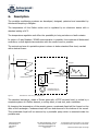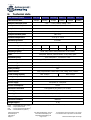
1
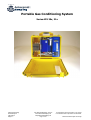
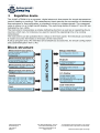
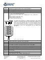
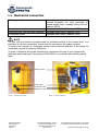
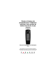
Ankersmid Sampling
User Manual
Portable Gas Conditioning System
Series APS
Ankersmid Sampling
Neerlandweg 22
2610 Wilrijk
Belgium
User Manual APS Edition 11/2010
www.ankersmidsampling.com
[email protected]
Page 1 of 20
© Reproduction of this document or its content
is not allowed without permission of Ankersmid.
Technical Details Subject to Change
Portable Gas Conditioning System
Series APS 30x, 31x
Ankersmid Sampling
Neerlandweg 22
2610 Wilrijk
Belgium
User Manual APS Edition 11/2010
www.ankersmidsampling.com
[email protected]
Page 2 of 20
© Reproduction of this document or its content
is not allowed without permission of Ankersmid.
Technical Details Subject to Change
List of contents
A. Illustrations………………………………………………………………………………………………
4
B. Used terms and signal indications ………………………………………………………………
5
C. Electrical standards……………………………………………………………………………………
5
D. Safety instructions ……………………………………………………………………………………
6
E. Warranty …………………………………………………………………………………………………
7
F. Introduction ……………………………………………………………………………………………
7
F.1. Serial number ……………………………………………………………………………………
7
F.2. Power supply ……………………………………………………………………………………
7
G. Description ………………………………………………………………………………………………
8
H. Technical data …………………………………………………………………………………………
9
I. Regulation device………………………………………………………………………………………
10
J. Versions, options, consumable and spare parts ……………………………………………
13
K. Receipt & storage of goods ………………………………………………………………………
17
L. Preparation for installation…………………………………………………………………………
17
L.1 Mechanical connection…………………………………………………………………………
18
L.2 Electrical connection……………………………………………………………………………
19
M. Mounting…………………………………………………………………………………………………
19
N. Maintenance ……………………………………………………………………………………………
19
N.1 Changing the pump hose ……………………………………………………………………
20
N.2 Replacing the filter cartridge (optional)…………………………………………………
20
O. Shutting down.…………………………………………………………………………………………
20
Ankersmid Sampling
Neerlandweg 22
2610 Wilrijk
Belgium
User Manual APS Edition 11/2010
www.ankersmidsampling.com
[email protected]
Page 3 of 20
© Reproduction of this document or its content
is not allowed without permission of Ankersmid.
Technical Details Subject to Change
A. List of illustrations
Figure 1
Standard flow chart of a gas sampling line …………………………………
8
Figure 2
Exchanger with humidifier …………………………………………………………
14
Figure 3
Outside connections …………………………………………………………………
18
Figure 4
Inside connections ……………………………………………………………………
18
Ankersmid Sampling
Neerlandweg 22
2610 Wilrijk
Belgium
User Manual APS Edition 11/2010
www.ankersmidsampling.com
[email protected]
Page 4 of 20
© Reproduction of this document or its content
is not allowed without permission of Ankersmid.
Technical Details Subject to Change
B.
Used terms and signal indications
QUALIFIED PERSONNEL
NOTE
IMPORTANT
C.
Persons with necessary qualification, who are familiar with
installation use and maintenance of the product
The signal is used according to DIN 4844 and
EU Recommendation 91/C53/06
Important information about the product or parts
referring to operating in hazardous areas
Electrical standards
CE – Certification
The product described in this operating manual complies with following EC directives:
EMV-Instruction
The requirements of the EC directive 89/336/EWG “Electromagnetic compatibility“ are met.
Low Voltage Directive
This product corresponds to the electrical standard of safety regulations concerning the
low-voltage of the EC recommendation 73/23 EEC and the recommendation of
electromagnetic compatibility 89/336 EEC.
Declaration of conformity
The EU Declaration of conformity is available at Ankersmid Sampling.
Ankersmid Sampling
Neerlandweg 22
2610 Wilrijk
Belgium
User Manual APS Edition 11/2010
www.ankersmidsampling.com
[email protected]
Page 5 of 20
© Reproduction of this document or its content
is not allowed without permission of Ankersmid.
Technical Details Subject to Change
D.
Safety instructions
Please read these operating instructions very carefully before start up and use of the
equipment.
•
-
Please check before installing the equipment if the device is suitable for:
the exposed pressure
the exposed temperature
the exposed ambient conditions (e.g.: rain, moist, dust,…)
•
Attention must be paid to the requirements of IEC 364 (DIN VDE 0100) when
setting high-power electrical units with nominal voltages of up to 1000 V, together
with the associated standards and stipulations.
•
Work on electrical equipment should only be carried out by trained specialists.
•
Before connecting the equipment, be sure that the main voltage is equal to the
voltage mentioned on the type plate on the inside of he electrical box.
•
Beware that the apparatus and the control units are switched off before opening of
the protection body.
•
Installation, maintenance, monitoring and repairs can be done by authorised
personnel.
IMPORTANT:
This equipment is, in its standard version, not explosion-proofed!
Ankersmid Sampling
Neerlandweg 22
2610 Wilrijk
Belgium
User Manual APS Edition 11/2010
www.ankersmidsampling.com
[email protected]
Page 6 of 20
© Reproduction of this document or its content
is not allowed without permission of Ankersmid.
Technical Details Subject to Change
E.
Warranty
If the equipment fails, please contact your ANKERSMID SAMPLING dealer.
The warranty is covered for a period of 1 year countable from the first day of delivery (as
also specified in our normal terms and conditions of sale) when the apparatus (*) is
handled and assembled correctly, installed according good craftsmanship, treatment and
use or operation of the equipment.
The warranty covers repair at the factory at no cost, or the replacement at no cost of the
equipment free ex user location. In case of resend or reshipment, the probe must be
properly packed or in his original protective packaging or in a sufficient adapted recipient.
NOTE
Consumables are only covered by this warranty in case of production defaults.
F.
Introduction
ANKERSMID SAMPLING Portable gas conditioning systems are used in mobile gas analysis
to prepare a sample gas by filtering the gas according to any dust particles and by lowering
the dew point of humid gas to avoid condensate in the analyser. A good and stable gas dew
point avoids cross-interference if the analyser is sensitive to H2O.
F.1 Serial number
The serial number is mentioned on the type plate on the device.
F.2 Power supply
Depending on the country area the device is available for a power supply of 230V/50Hz or
115V/60Hz.
Ankersmid Sampling
Neerlandweg 22
2610 Wilrijk
Belgium
User Manual APS Edition 11/2010
www.ankersmidsampling.com
[email protected]
Page 7 of 20
© Reproduction of this document or its content
is not allowed without permission of Ankersmid.
Technical Details Subject to Change
G.
Description
The portable conditioning systems are developed, designed, patented and assembled by
Ankersmid Sampling in Belgium.
The temperature of this Peltier cooler unit is regulated by an electronic device with a
standard setting of 4°C.
The temperature regulation unit offers the possibility to bring out alarm or fault contacts.
In option a 2-way Modbus / RS485 communication is possible; this combines all Ankersmid
controllers, so that digital communication with the control room is possible.
The content and use of a portable system is shown in below standard flow chart, marked
with a dashed frame:
Gas sample probe
Analyser
Universal filter
Diaphragm gas pump
Heated sample line
Gas cooler
Peristaltic pump for
condensate removal
Figure 1
Standard flow chart of a gas sampling line
The standard exchanger, made of Duran glass with a PTFE screwed head, is cooled by a
complete system of a Peltier element, a cooling block, a heat sink, and a ventilator.
By lowering the temperature of the sample gasses, condensate liquid will be formed on the
sides of the exchanger. Condense drops will form and descend to the bottom of the vessel.
This condensate liquid will be removed by a peristaltic pump which is mounted inside the
portable case.
Ankersmid Sampling
Neerlandweg 22
2610 Wilrijk
Belgium
User Manual APS Edition 11/2010
www.ankersmidsampling.com
[email protected]
Page 8 of 20
© Reproduction of this document or its content
is not allowed without permission of Ankersmid.
Technical Details Subject to Change
H.
Technical data
APS Portable system
APS 301
APS 302
APS 303
APS 311
APS 312
APS 313
Gas flow rate max.
350Nl/h
350Nl/h
350Nl/h
150Nl/h
150Nl/h
150Nl/h
Sample outlet dew point
+1°C ..... +15°C, factory setting: +4°C
Dew point stability
±0,1°C
Sample inlet temperature
Max.190°C
Sample inlet connection
Stainless steel connection DN4/6mm, suitable for heated sample lines
Sample inlet dew point
Max. 80°C
Ambient temperature
+5°C up to +45°C
Maximum pressure
3 bar abs.
Material of gas wetted parts*
Heat exchanger head
PTFE
PVDF
SS316
PTFE
PVDF
SS316
Heat exchanger body
Glass
PVDF
SS316
Glass
PVDF
SS316
Diaphragm pump
Filter
Head: PPS, Valves: FFPM, Membrane: PTFE-coated
head, filter element, element holder: PTFE, body: glass
Peristaltic pump
Others
Tube: Novoprene®, Connectors: PVDF
Tubing: PTFE, Inlet connector: SS316, Outlet connector: PVDF
Number of gas inlets
1
Number of gas outlets
1 (standard), max. 2
Filter porosity*
Alarm contact
Total cooling capacity
2µm
Free programmable contact 1NO / 1NC, rating: 250V, 16A AC
Max. 225kJ/h
Max. 215kJ/h
Storage temperature
-25 °C up to +65 °C
Ready for operation
< 15 min
Power supply
230V/50Hz or 115V/60Hz
Power consumption
100VA
Electrical connection
Cold appliance plug with 1,5 m of cable
Housing
Portable plastic case
Housing dimensions
52,4mm x 42,8mm x 20,6mm (W x H x D)
Electrical protection
Fuse 2A
Electrical standard
EN61010
Weight approx.
12 kg
*Maximum values in technical data’s must be rated in consideration of total cooling capacity at 25°C ambient temperature and 4°C outlet dew point
PTFE
PVDF
PPS
FFPM
= Polytetrafluoroethylene (Teflon®)
= Polyvinylidenfluoride
= Polypropylenesulphide (Ryton®)
= Perfluorelastomer (Kalrez®)
Ankersmid Sampling
Neerlandweg 22
2610 Wilrijk
Belgium
User Manual APS Edition 11/2010
www.ankersmidsampling.com
[email protected]
Page 9 of 20
© Reproduction of this document or its content
is not allowed without permission of Ankersmid.
Technical Details Subject to Change
I.
Regulation device
Ankersmid Sampling
Neerlandweg 22
2610 Wilrijk
Belgium
User Manual APS Edition 11/2010
www.ankersmidsampling.com
[email protected]
Page 10 of 20
© Reproduction of this document or its content
is not allowed without permission of Ankersmid.
Technical Details Subject to Change
The display of the regulation unit will directly indicate the temperature in real time.
The setting temperature is set by our manufacturing department.
Settings (alarm etc.) can be done according as follows:
Ankersmid Sampling
Neerlandweg 22
2610 Wilrijk
Belgium
User Manual APS Edition 11/2010
www.ankersmidsampling.com
[email protected]
Page 11 of 20
© Reproduction of this document or its content
is not allowed without permission of Ankersmid.
Technical Details Subject to Change
Ankersmid Sampling
Neerlandweg 22
2610 Wilrijk
Belgium
User Manual APS Edition 11/2010
www.ankersmidsampling.com
[email protected]
Page 12 of 20
© Reproduction of this document or its content
is not allowed without permission of Ankersmid.
Technical Details Subject to Change
J.
Versions, options, consumable and spare parts
APS 301
APS 302
APS 303
APS 311
APS 312
APS 313
APS 001
APS 002
APS 003
APS 004
APS 005
APS 006
Portable gas conditioning system for 350Nl/h. In an heavy duty ABS portable housing,
consisting of: Peltier cooler with exchanger made of Duran® Glass (body) and PTFE (head),
universal filter AUF 102, diaphragm pump AMP 11E, peristaltic pump ACP 001, Pre-filter
type APS 900 (25µm) to protect peristaltic pump. Internal tubing: PTFE. Power: 230V/50Hz
Portable gas conditioning system for 350Nl/h. In an heavy duty ABS portable housing,
consisting of: Peltier cooler with exchanger made of PVDF (body and head), universal filter
AUF 102, diaphragm pump AMP 11E, peristaltic pump ACP 001, Pre-filter type APS 900
(25µm) to protect peristaltic pump. Internal tubing: PTFE. Power: 230V/50Hz
Portable gas conditioning system for 350Nl/h. In an heavy duty ABS portable housing,
consisting of: Peltier cooler with exchanger made of Stainless Steel 316 (body and head),
universal filter AUF 102, diaphragm pump AMP 11E, peristaltic pump ACP 001, Pre-filter
type APS 900 (25µm) to protect peristaltic pump. Internal tubing: PTFE. Power: 230V/50Hz
Portable gas conditioning system for 200Nl/h. In an heavy duty ABS portable housing,
consisting of: Peltier cooler with exchanger made of Duran® Glass (body) and PTFE (head),
universal filter AUF 102, diaphragm pump AMP 26E, peristaltic pump ACP 001, Pre-filter
type APS 900 (25µm) to protect peristaltic pump. Internal tubing: PTFE. Power: 230V/50Hz
Portable gas conditioning system for 200Nl/h. In an heavy duty ABS portable housing,
consisting of: Peltier cooler with exchanger made of PVDF (body and head), universal filter
AUF 102, diaphragm pump AMP 26E, peristaltic pump ACP 001, Pre-filter type APS 900
(25µm) to protect peristaltic pump. Internal tubing: PTFE. Power: 230V/50Hz
Portable gas conditioning system for 200Nl/h. In an heavy duty ABS portable housing,
consisting of: Peltier cooler with exchanger made of Stainless Steel 316 (body and head),
universal filter AUF 102, diaphragm pump AMP 26E, peristaltic pump ACP 001, Pre-filter
type APS 900 (25µm) to protect peristaltic pump. Internal tubing: PTFE. Power: 230V/50Hz
Option for APS/ASS 3xx with flow meter (max. 2 pcs.). Material: acylic glass.
Range: 0,1-1,2 Nl/min
Option for APS/ASS 3xx with flow meter (max. 2 pcs.). Material: acylic glass.
Range: 0,5-2,5 Nl/min
Option for APS/ASS 3xx with flow meter (max. 2 pcs.). Material: acylic glass.
Range: 0,5-6 Nl/min
Option for APS/ASS 3xx with flow meter (max. 2 pcs.). Material: acylic glass.
Range: 2-14 Nl/min
Option for APS/ASS 3xx with flow meter (max. 2 pcs.). Material: acylic glass.
Range: 5-30 Nl/min
Option for APS/ASS 3xx with liquid alarm unit in APS 30x. Consisting of: filter unit AUF 104
(instead of AUF 102) with drain, Liquid alarm ALA 002, ALA 102 Electronic device.
Automatic switch off of sample pump at condensate inrush
Ankersmid Sampling
Neerlandweg 22
2610 Wilrijk
Belgium
User Manual APS Edition 11/2010
www.ankersmidsampling.com
[email protected]
Page 13 of 20
© Reproduction of this document or its content
is not allowed without permission of Ankersmid.
Technical Details Subject to Change
APS 007
APS 008
APS 009
APS 010
APC 001
Option for APS/ASS 3xx with digital regulation unit ATC 600 (max 10A)
for heated line integrated in APS 3xx. Incl. connector and wiring
Option for APS/ASS 3xx with 3-way ball-valve integrated in the gas inlet
Option for APS/ASS 3xx with 5-way ball-valve integrated in the gas inlet
Option for APS/ASS 3xx with adjustable carrying strap
Option APS/ASS with complete heat exchanger unit with humidifier and calibration gas
inlet. Only for APS/ASS/ADS series 30x.
Connections: gas in: G1/4”, gas out: G1/4”, calibration gas in: G1/4”, condensate in:
G3/8”.
Material for APC 301: glass, PVDF, PTFE.
Material for APC 302: PVDF, PTFE.
Incl. Thermal conductivity paste, 5gr
This special heat exchanger is suitable for calibration under perfect
conditions. The principle is that zero and calibration gas is injected in the
special head of this exchanger where they will be ‘humidified’ with the
return of liquid condensate (See Figure 7). This way the calibration or zero
gas will be at the same dew point as the sampling gas. The heat exchanger
with humidifier is one to one interchangeable with the standard heat
exchanger.
Figure 2 Exchanger with humidifier
ACP 001
ACP
ACP
ACP
ACP
ACP
ACP
ACP
ACP
ACP
020
022
023
032
034
035
037
039
045
ACP 050
ACP 500
Peristaltic pump ASR25, capacity 0,25l/h, connection DN4/6. Materials: Novoprene®, PVDF.
Pressure: 200mbar abs -2,2bar abs., power: 230/115VAC
Set of Novoprene® tube with PVDF connectors for ACP, for tube DN4/6.
Set of Viton® tube with PVDF connectors for ACP, for tube DN 4/7
Set of Acidflex® tube DN3x1 with PVDF connectors for ACP, for tube DN4/6
Set of pressure springs for driver ASR25 (4 Pcs.: 2 left, 2 right)
Driver complete for ASR25 (green chassis + white pulleys + springs)
Contact pulley for ASR25 (2 pcs.)
Conveying belt for ASR25
S-bolt for ASR25
Pump head (black) complete with S-bolt without motor and gear for ASR25
(without driver & conveying belt)
Spring for Novoprene®/Viton®/Acidflex® tubing fixing (2 pcs.)
Complete motor and gear for ASR25 for ACP 001 (5 RPM)
Ankersmid Sampling
Neerlandweg 22
2610 Wilrijk
Belgium
User Manual APS Edition 11/2010
www.ankersmidsampling.com
[email protected]
Page 14 of 20
© Reproduction of this document or its content
is not allowed without permission of Ankersmid.
Technical Details Subject to Change
ACC 150
ACC 151
ACC 152
ACC 153
APC 101
APC 103
APC 102
APC 104
APC 106
APC 110
APC 112
APC
APC
APC
APC
APC
APC
114
113
120
121
130
132
APC 133
APC
APC
APC
APC
APC
APC
140
142
143
144
136
123
AUF 301
AUF 303
APC 021
Heat exchanger outer part for 150Nl/h, with 1 x GL25, material: Duran® glass. Incl.
thermal conductivity paste (5gr).
Heat exchanger complete for 150Nl/h. Material: body made of Duran® glass, head made
of PTFE. Connections: G 1/4"i + G 1/4"i and 1x G 3/8"i.
Incl. thermal conductivity paste (5gr).
Heat exchanger complete for 150Nl/h. Material: body/head: SS316.
Connections: G 1/4"i + G 1/4"i and 1x G 3/8"i. Incl. thermal conductivity paste (5gr).
Heat exchanger complete for 150Nl/h. Material: body made of PVDF,
head made of PTFE. Connections: G 1/4"i + G 1/4"i and 1x G 3/8"i. Incl. thermal
conductivity paste (5gr).
Heat exchanger complete for 350Nl/h. Body: Duran® glass, head: PTFE, volume displacer:
PVDF. Connections: Gas in: 1x G1/4", gas out 2xG1/4", condensate out: 1x GL25-12mm.
Incl. thermal conductivity paste, 5gr
Heat exchanger for 350Nl/h. Outer part with 1x GL25, material: Duran® glass.
Incl. thermal conductivity paste, 5gr
Heat exchanger complete for 350Nl/h. Body: PVDF, head: PTFE.
Connections: Gas in: 1x G1/4", gas out 2xG1/4", condensate out: 1x G3/8".
Incl. thermal conductivity paste, 5gr
Heat exchanger for 350Nl/h. Outer part, material: PVDF.
Incl. thermal conductivity paste,, 5gr
Heat exchanger for 350Nl/h. Inner part, material: PVDF
Heat exchanger complete for 350Nl/h. Material: body/head: SS316.
Connections: Gas in: 1x G1/4", gas out 2xG1/4", condensate out: 1x G3/8".
Incl. thermal conductivity paste, 5gr
Heat exchanger for 350Nl/h. Outer part, material: SS316.
Incl. thermal conductivity paste, 5gr
Heat exchanger for 350Nl/h. Inner part, material: SS316
Tent/wick for humidifier of heat exchanger
Thermal conductivity paste -40 to +150°C, 5g
Thermal conductivity paste -40 to +150°C, 50g
Power transistor for APC 3xx series
Temperature sensor PT100 for APC 3xx series
Peltier element for APC 3xx series.
Incl. thermal conductivity paste, -20 - +140°C, 5gr
Power supply for APC 3xx series
Insulation set for APC 3xx series
Electronic controller 110/240VAC for APC 3xx series
Electronic controller 110/240VAC for APC 3xx series, with RS485 interface
Fan for APC 3xx series
Fine fuse 1AT (5 pc.) for APC 3xx series
Extra charge for liquid alarm sensor type ALA 001 mounted to universal filter with glassbody (GL25). Incl. rail-mounting electronics type ALA 101, 230VAC. Max. 3 bar a
Extra charge for liquid alarm sensor type ALA 002 mounted to universal filter with glassbody (GL25). Incl. rail-mounting electronics type ALA 102, 230VAC. Max. 3 bar a
Connector for optical liquid-alarm sensor ALS 001 connected to digital controller, with 1
contact NO
Ankersmid Sampling
Neerlandweg 22
2610 Wilrijk
Belgium
User Manual APS Edition 11/2010
www.ankersmidsampling.com
[email protected]
Page 15 of 20
© Reproduction of this document or its content
is not allowed without permission of Ankersmid.
Technical Details Subject to Change
AMP 11E
AMP 002
AMP 003
AMP 004
AMP 26P
AMP 603
AMP 605
AMP 604
Analytical diaphragm pump AMP 11E. material: membrane: PTFE-coated, head: PPS,
valves: FFPM, capacity: 11Nl/min @ atm. pressure. Connections: G 1/8"i, IP00. 230V
FPM (Viton®) valve and sealing ring for AMP 11E (2 pcs./pump needed)
Diaphragm for AMP 11E, material: PTFE-coated
Valve and sealing ring for AMP 11E, material: FFPM (Kalrez®) (2 pcs./pump needed)
Analytical diaphragm pump AMP 26P, material: membrane: PTFE-coated, head: Ryton, orings & valves: FFPM (Kalrez®). Capacity: 5,5Nl/min @ atm. pressure. Connections: G1/8"i,
IP00. 230V
Diaphragm for AMP 26P, material: PTFE-coated
Valve plate for AMP 26P, material: FFPM (Kalrez®) (2 pcs./pump needed)
Sealing ring for AMP 26P, material: FFPM (Kalrez®) (2 pcs./pump needed)
AUF 001
AUF 002
AUF 006
AUF 007
AUF 008
AUF 012
AUF 014
AUF 030
AUF 801
AUF 802
AUF 900
AUF 904
AUF 905
AUF 906
ASP 081
AUF-1-P-GO-T02-MB. Universal filter with filter head and filter element holder made of
PTFE. Filter body made of Duran® glass. Filter element made of PTFE with a porosity of
2µm, length 75mm. Gas in-/out connection: G1/4". Incl. bracket for wall-mounting
AUF-1-P-GL-T02-MB. Universal filter with filter head and filter element holder made of
PTFE. Filter body made of Duran® glass, with connection GL25 for condensate outlet or
liquid alarm sensor. Filter element made of PTFE with a porosity of 2µm, length 75mm.
Gas in-/out connection: G1/4". Incl.: bracket for wall-mounting, Union nut GL 25/15 (ACF
750), PTFE sealing ring GL 25-12 mm (ACF 763)
AUF-1-P-GO-G0.1-MB. Universal filter with filter head and filter element holder made of
PTFE. Filter body made of Duran® glass. Filter element made of glass-fibre with a porosity
of 0.1µm, Gas in-/out connection: G1/4". Incl. bracket for wall-mounting
AUF-1-P-GL-G.1-MB. Universal filter with filter head and filter element holder made of
PTFE. Filter body made of Duran® glass, with connection GL25 for condensate outlet or
liquid alarm sensor. Filter element made of glass-fibre with a porosity of 0.1µm, length
75mm. Gas in-/out connection: G1/4". Incl.: bracket for wall-mounting, Union nut GL 25/15
(ACF 750), PTFE sealing ring GL 25-12 mm (ACF 763)
Filter element, material: PTFE, length: 75mm, porosity: 2µm
Filter element, material: PTFE, length: 75mm, porosity: 20µm
Filter element, material: SS316, length: 75mm, porosity: 2µm
Filter element, material: SS316, length: 75mm, porosity: 3µm
Filter element, material: SS316, length: 75mm, porosity: 20µm
Filter element, material: ceramics, length: 75mm, porosity: 2µm
Filter element, material: ceramics, length: 75mm, porosity: 20µm
Filter element, material: glass fibre, length: 75mm, porosity: 2µm (pack of 25pcs.)
Filter Glass for filter elements 75mm without drain outlet (Glass only)
Filter Glass for filter elements 75mm with drain outlet (Glass only)
Filter element holder for standard filter elements of 75mm, material: PVDF
O–Ring for filter head, material: Viton®
Filter head, material: PTFE. Incl.: O-ring, mounting bracket
O–Ring for filter element AUF 091 / AUF 092. Material: Viton®
Gasket for filter element, material: Viton®
APS 900
Pre-filter with filter element, porosity: 25µm
AUF 102
AUF 104
AUF 132
AUF 134
Ankersmid Sampling
Neerlandweg 22
2610 Wilrijk
Belgium
User Manual APS Edition 11/2010
www.ankersmidsampling.com
[email protected]
Page 16 of 20
© Reproduction of this document or its content
is not allowed without permission of Ankersmid.
Technical Details Subject to Change
K.
Receipt and storage of goods
The device is a complete pre-installed unit.
The arrived goods should be carefully unpacked as soon as possible in order to control the
good and correct condition.
The goods and the delivery note should be compared. If any difference is noted please
contact your Ankersmid Sampling contact person.
The delivery should be checked for any transport damage. If any anomaly is noted, please
contact the transport insurer immediately notifying of the damage.
The goods should be stored in a frost-protected area.
L.
Preparation for installation
The safety rules and regulations for the prevention of accidents must be observed when
carrying out the installation.
NOTE
Especially the information in chapter D. “Safety instructions” must be applied.
This device is to be used in only in VERTICAL position. The device is operating with open
and closed lid, but we recommend to always keep the housing closed in order to protect the
products inside.
The device should be placed in a ventilated area, away from heat sources and magnetic
fields. If the equipment is placed outside, beware that it is prevented against rain, dust,
frost, and direct sunlight.
IMPORTANT
A standard version of the device is not an explosion-proofed apparatus!
Ankersmid Sampling
Neerlandweg 22
2610 Wilrijk
Belgium
User Manual APS Edition 11/2010
www.ankersmidsampling.com
[email protected]
Page 17 of 20
© Reproduction of this document or its content
is not allowed without permission of Ankersmid.
Technical Details Subject to Change
L.1 Mechanical connection
Sample gas inlet
Sample gas outlet
Calibration gas, zero gas inlet (Optional)
Condensate outlet
Connecting adapter flange with integrated
bending protection for rigid mountage of
heated sample lines, including fitting and nut.
Material: SS316
Bulkhead union DN4/6. Material: PVDF
Bulkhead union DN4/6. Material: PVDF
Bulkhead union DN4/6. Material: PVDF
NOTE
The gas inlet and outlet is located inside the portable housing in the heated area. It is
important to not mix connections. Ensure that the connections are sealed correctly.
To ensure free removal of condensate, please ensure that the diameter of the tubing for
condensate removal it minimum DN4/6mm!
To grant a functional and proper mounting we recommend the use of union pieces with
taper pipe and thread type R according to DIN 2999/1 in connection with suitable sealing
tape.
Sample gas inlet
Power supply
condensate outlet
Sample gas outlet
Figure 3 Outside connections
Ankersmid Sampling
Neerlandweg 22
2610 Wilrijk
Belgium
Figure 4 Inside connections
User Manual APS Edition 11/2010
www.ankersmidsampling.com
[email protected]
Page 18 of 20
© Reproduction of this document or its content
is not allowed without permission of Ankersmid.
Technical Details Subject to Change
L.2 Electrical connection
NOTE
At connecting the equipment please check that the supply voltage is identical with the
information provided on the type plate.
Attention must be paid to the requirements of IEC 364 (DIN VDE0100) when setting highpower electrical units with nominal voltages of up to 1000V, together with the associated
standards and stipulations.
Power supply:
M.
230VAC standard (115VAC on request)
Mounting
The conditioning system could be used in portable and stationary conditions and with
correct selection of the installation point and proper installation. When used and properly
installed in the prescript area ANKERSMID SAMPLING guarantee a long-time of
maintenance-free and satisfaction use.
N.
Maintenance
Before the maintenance it is necessary that the specific safety procedures regarding the
system and operational process are observed.
NOTE
It is necessary to switch off the power supply before any assembly, maintenance or repair
work is carried out!
Ankersmid Sampling
Neerlandweg 22
2610 Wilrijk
Belgium
User Manual APS Edition 11/2010
www.ankersmidsampling.com
[email protected]
Page 19 of 20
© Reproduction of this document or its content
is not allowed without permission of Ankersmid.
Technical Details Subject to Change
N.1 Changing the pump hose
When the condensate pump is operated for a long time, the pump hose eventually wears
out Condensate may leak from the pump hose. In this case, the pump hose must be
replaced immediately as there is a risk of external air being sucked from porous points,
which may lead to false readings. We recommend replacement of the pump hose after
every 3 months as a precautionary measure. Follow the simple guidelines for handling the
condensate before and while changing the condensate tube. The device must be switched
off before changing the condensate tubes. Hose connection bolted joints must be loosened
and hoses must be disconnected.
NOTE
Condensate may leak
The lock of the pump hose must then be rotated clockwise till the bearing surface can be
dismantled. After dismantling the bearing surface, the pump hose can be disconnected from
it along with the hose connection bolted joints. The new pump hose must then be inserted
into the bearing surface. The bearing surface of the condensate pump must be mounted
again and the lock must be rotated anti-clockwise in order to fix the bearing surface.
Condensate lines must be connected again after locking the bearing surface.
N.2 Replacing the Teflon filter cartridge (optional)
Cartridge of the filter must be replaced in case of contamination. The sample gas pump
must be switched off before changing it. The clamping nut of the filter casing can then be
removed.
NOTE
the filter glass may fall out of the clamping nut
After unscrewing the filter element holder the filter cartridge can be replaced by taking it
out and inserting a new one in.
O.
Closing down
NOTE
The area in which the device is placed when not in use must be kept free of frost at all
times. If the device unit is putting out of action for a short time no particular measures
need to be taken.
We recommended sweeping the device with inert gas or ambient air while the unit is
putting out of action for a longer time. Condensate has to be removed completely from the
cooler.
NOTE
Aggressive condensate is possible. Wear protective glasses and proper protective clothing!
Ankersmid Sampling
Neerlandweg 22
2610 Wilrijk
Belgium
User Manual APS Edition 11/2010
www.ankersmidsampling.com
[email protected]
Page 20 of 20
© Reproduction of this document or its content
is not allowed without permission of Ankersmid.
Technical Details Subject to Change