1
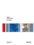
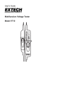
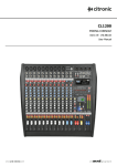
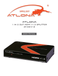
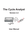
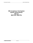
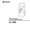
Power Analyzer
PA4000 Datasheet
Applications
Power conversion
Power generation
Inverters
Motor drives
Electrical propulsion
UPS
Frequency converters
Tektronix PA4000 Power Analyzers deliver highly accurate, multi-channel
power, energy, and efficiency measurements. Precisely-matched inputs,
unique Spiral Shunt™ technology, and advanced signal processing deliver
high accuracy even with highly modulated waveforms and crest factors as
high as 10. The versatile PA4000 offers comprehensive power
measurements. Dual current shunts provide optimal resolution from
microwatts to kilowatts. Harmonics analysis up to the 100th harmonic, and
motor analysis with torque and speed inputs are included in the standard
instrument. Every PA4000 comes with multiple PC interfaces, PC software,
and USB flash drive support to help you collect and analyze data.
Key features
1 to 4 Input Modules allows several configurations to match your
application
High measurement accuracy of 0.01% (basic voltage & current
accuracy) for demanding test requirements
Dual internal current shunts for each module maximize accuracy for
high- and low-current measurements
Unique Spiral ShuntTM design maintains stability over variations in
current, temperature, etc. (patent applied for)
Electric and hybrid vehicle
High-efficiency lighting
Consumer electronics
Standby power
Flexible voltage and current input choices to
fit your application
The PA4000 is the only instrument of its kind to feature both high- and lowrange internal current shunts in each input module. The 30-Amp shunt is
perfect for many applications and can accept up to 200 A peak, but for
measuring low-current devices, the 1 A shunt provides increased resolution
and accuracy for measurements down into the microamp range. For
measuring currents over 30 Amps, a selection of matching external current
transducers are available in several styles, including high-accuracy
transducers up to 1000 A.
The PA4000's voltage inputs can accept up to 1000 VRMS, 2000 Vpeak,
continuous.
Proprietary frequency detection algorithms ensure rock-solid frequency
tracking even on noisy waveforms
Application-specific test modes simplify instrument setup and reduce
the likelihood of user error
Easy data export to USB flash drive or remote PC software, for
reporting and/or remote control
Many standard features such as comm ports and harmonic analysis
eliminate costly upgrade options
PA4000 Rear Panel - Input Modules
www.tektronix.com 1
Datasheet
Unique Spiral Shunt™ technology (patent
applied for)
The PA4000 employs an innovative Spiral Shunt design that ensures
stable, linear response over a wide range of input current levels, ambient
temperatures, crest factors, and other variables. This new design is
superior to other shunt technologies and contributes to the instrument's
reliable accuracy and repeatability over a wide range of signal conditions
common in today's power conversion technologies. The spiral construction
not only minimizes stray inductance (for optimum high frequency
performance) but also provides for high overload capability and improved
thermal stability.
Application-specific test modes
Some applications require special instrument settings to ensure proper
measurements. The PA4000 simplifies setup for these applications by
automatically choosing instrument settings and parameters that are
optimized for each type of measurement application, resulting in more
reliable measurement results with less opportunity for user setup error.
Selection of application-specific test modes.
PWM motor drive mode
PWM motor mode is designed to overcome the difficulties associated with
making measurements on the complex waveforms commonly found on the
motor drives. High frequency sampling is combined with digital filtering to
reject the carrier frequency and extract the motor frequency while still using
prefiltered data for power parameters
Standby power mode
Spiral Shunt for 30 A input
Spiral Shunt for 1 A input
2 www.tektronix.com
Driven by consumer demand and energy efficiency regulations (such as
ENERGY STAR), there is an ever-increasing need to measure power
consumption of products while they are in standby mode. One of the most
widely used standards for measurement is IEC 62301. Part of this standard
requires the measurement of power over a prolonged period of time without
missing any short duration power events. The PA4000 standby power
mode provides continuous sampling of voltage and current to produce an
accurate Watts measurement over the user specified period.
PA4000 Power Analyzer
Ballast mode
Ballast mode synchronizes measurements for highly modulated electronic
ballast waveforms. In modern electronic lighting ballasts, it is often difficult
to make accurate measurements because the output signals are high
frequency waveforms that are heavily modulated by the power frequency.
Ballast mode provides a way of locking the measurement period to the
power frequency.
Integrator mode
Integrator mode is used to provide measurements for determining energy
consumption (Watt-hours, Ampere-hours, etc.). In addition, for certain
parameters, average values are also available.
PWRVIEW PC software for the PA4000 Power
Analyzers
PWRVIEW is a supporting software application for Windows PCs that
compliments and extends the functionality of the PA4000. PWRVIEW
enables you to do the following:
Communicate with PA4000 over any of the instrument's comm ports
Change instrument settings remotely
Transfer, view, and save measurement data in real-time from the
instrument, including waveforms, harmonic bar charts, and plots
Log measurement data over a period of time
Standard harmonics analysis
The PA4000 features harmonics analysis to the 100th harmonic as a
standard feature. Harmonics, THD, and related measurements can all be
analyzed simultaneously with other power parameters. Accurate
measurement of harmonic amplitude, phase, and harmonic power are
included, which are critical to the analysis of losses in rotating machinery.
Communicate with and download data from multiple PA4000
instruments simultaneously
Create formulae for the calculation of power conversion efficiency and
other values
Export measurement data to .csv format for import into other
applications
Automate instrument setup, data collection, and report generation for
key applications with just a few clicks, using wizard-driven interfaces
Perform automated full compliance testing for Low Power Standby per
IEC62301, Edition 2
Other test automation will be added with future releases
Harmonics bar chart display mode.
www.tektronix.com 3
Datasheet
Standard communication ports
The PA4000 comes standard with USB, Ethernet, and
RS-232 communication ports, plus a front-mounted USB port for data
export to a flash drive. GPIB is available as a factory-installed option.
PA4000 rear panel, with communication ports
Specifications
Measurements
All measurements taken at 1 MHz with a sample rate of 1 Megasample/second.
Measurement accuracy specifications are valid up to a Crest Factor of 10.
The recommended calibration interval is one year.
Available measurements
4 www.tektronix.com
VRMS - Volts RMS
VDF - Volts Distortion Factor
ARMS - Amps RMS
VTIF - Volts Telephone Influence Factor
WATT - Watts
ATHD - Amps Total Harmonic Distortion
VA - Volt-Amps
ADF - Amps Distortion Factor
VAR - Volt-Amps Reactive
ATIF - Amps Telephone Influence Factor
FRQ - Frequency
VF - Fundamental Volts rms
PF - Power factor
AF - Fundamental Amps rms
VPK+ - Volts peak (positive)
IMP - Impedance
VPK- - Volts peak (negative)
RES - Resistance
APK+ - Amps peak (positive)
REA - Reactance
APK- - Amps peak (negative)
HR - Integrator time
VDC - Volts DC
WHR - Watt Hours
ADC - Amps DC
VAH - VA Hours
VRMN - Volts rectified mean
VRH - VAr Hours
ARMN - Amps rectified mean
AHR - Amp Hours
VCF - Voltage crest factor
WAV - Average Watts
ACF - Current crest factor
PFAV - Average Power Factor
VTHD - Volts Total Harmonic Distortion
CVAR - Correction VArs
PA4000 Power Analyzer
Measurements
Voltage and current ranges
Voltage ranges
2000 Vpeak, 1000 Vpeak, 500 Vpeak, 200 Vpeak, 100 Vpeak, 50 Vpeak, 20 Vpeak, 10 Vpeak, 5 Vpeak, 2 Vpeak
Current ranges (30 A shunt)
200 Apeak, 100 Apeak, 50 Apeak, 20 Apeak, 10 Apeak, 5 Apeak, 2 Apeak, 1 Apeak, 0.5 Apeak, 0.2 Apeak, 0.1 Apeak
Current ranges (1 A shunt)
5 Apeak, 2.5 Apeak, 1.25 Apeak, 0.5 Apeak, 0.25 Apeak, 0.125 Apeak, 0.05 Apeak, 0.025 Apeak, 0.0125 Apeak, 0.005 Apeak, 0.0025 Apeak
Current ranges (external
shunt)
3 Vpeak, 1.5 Vpeak, 0.75 Vpeak, 0.3 Vpeak, 0.15 Vpeak, 0.075 Vpeak, 0.03 Vpeak, 0.015 Vpeak, 0.0075 Vpeak, 0.003 Vpeak, 0.0015 Vpeak
Measurement accuracy - voltage
and current
Voltage accuracy, VRMS ( 45 Hz ± 0.01% of Reading ± 0.04% of Range
- 850 Hz ) 1
Voltage accuracy, VRMS ( 10 Hz ± 0.05% of Reading ± 0.05% of Range ± (0.02*F)% of Reading ± 0.02 V (typical)
- 45 Hz, 850 Hz - 1 MHz )
Voltage accuracy, DC
± 0.05% of Reading ± 0.1% of Range ± 0.05 V
Voltage accuracy, Vrmn
± 0.2% of Reading ± 0.1% of Range ± 0.1 V
Effect of common mode
(typical)
1000 V, 60 Hz < 10 mV
100 V, 100 kHz < 50 mV
Current accuracy, ARMS ( 45 Hz ± 0.01% of Reading ± 0.04% of Range
- 850 Hz ) 1
Current accuracy, ARMS ( 10 Hz ± 0.05% of Reading ± 0.05% of Range ± (0.02*F)% of Reading ± (20 µV/Zext) (typical)
- 45 Hz, 850 Hz - 1 MHz )
Current accuracy, DC
± 0.05% of Reading ± 0.1% of Range ± (50 µV/Zext)
Current accuracy, Armn
± 0.2% of Reading ± 0.1% of Range ± (100 µV/Zext)
Measurement accuracy - power
Watts accuracy (45 - 850 Hz) 1
± 0.02% of Reading ± 0.06% of Range
VA accuracy (45 - 850 Hz)
± 0.02% of Reading ± 0.06% of Range
1
VAR accuracy
PF Accuracy
VA ± VAerror 2 - W ± Werror 2 - VA2 - W2
Cos θ -cos [ θ± ( Vh1 ph.err± Ah1 ph.err)] ± 0.001
Measurement accuracy - Harmonic
magnitude and phase 2
1
Voltage harmonics (45 Hz 850 Hz) (typical for 10 Hz to
45 Hz and 850 Hz to 1 MHz)
± 0.08% of Reading ± 0.08% of Range ± (0.02*F)% of Reading ± 0.02 V
Voltage harmonics phase
(45 Hz - 850 Hz) (typical for
10 Hz to 45 Hz and 850 Hz to
1 MHz)
± 0.025 ± [ 0.005 * Vrange / Vreading )] ± (0.1 / Vrange) ± ( 0.002 *F )
These specifications apply under the following conditions:
Volts = 10 V range or higher
30 A shunt = 0.5 A range or higher
1 A shunt = 0.025 A range or higher
Signal > 30% of range
Watts accuracy @ PF = 1
2
F is the frequency measured in kHz. In the case of harmonics, F is the harmonic frequency.
Zext is the shunt impedance (0.6 Ω for 1 A shunt, 9.375 mΩ for 30 A shunt). It is assumed that the waveform measured is a sine wave.
Measurement conditions during calibration: Instrument default settings unless otherwise stated, Sine waves applied to V and I inputs, 30 minute warm-up, Temperature 23 °C ±5 °C.
www.tektronix.com 5
Datasheet
Measurements
Current harmonics (45 Hz 850 Hz) (typical for 10 Hz to
45 Hz and 850 Hz to 1 MHz)
± 0.08% of Reading ± 0.08% of Range ± (0.02*F)% of Reading ± (20 µV /Zext)
Current harmonics phase
(45 Hz - 850 Hz) (typical for
10 Hz to 45 Hz and 850 Hz to
1 MHz)
± 0.025 ± [0.005 * Arange / Areading)] ± (0.001 / Arange * Zext)) ± (0.002 *F)
Physical characteristics
Dimensions
Height
13.2 cm.
5.2 in.
Width
42 cm.
16.5 in.
Depth
31 cm.
12.5 in.
Weight
Net (without lead set)
8.8 kg
19.5 lb.
Temperature
Storage
-20
Operating
0
6 www.tektronix.com
○
○
C to +60
○
○
C
C to +40
C
PA4000 Power Analyzer
Ordering information
PA4000 models
A PA4000 must be ordered with one of the following options:
Opt. 1CH
One input module installed
Opt. 2CH
Two input modules installed
Opt. 3CH
Three input modules installed
Opt. 4CH
Four input modules installed
Standard accessories
--
Voltage Lead Set (one per input module)
--
Country-specific power cord
063-4498-xx
CD containing all relevant documentation and translated user manuals
--
USB Host - to - Device interface cable
--
Certificate of calibration documenting traceability to National Metrology Institute(s) and ISO9001 Quality System Registration
--
Five year product warranty.
Instrument options
Opt. GPIB
GPIB Interface
Opt. 15V
Power Output for External Current Transducers
Language options
No Language Options - Standard documentation CD includes user manual in English, French, German, Spanish, Japanese,
Portuguese, Simplified Chinese, Traditional Chinese, Korean, and Russian.
Power cord options
Opt. A0
North America power plug (115 V, 60 Hz)
Opt. A1
Universal Euro power plug (220 V, 50 Hz)
Opt. A2
United Kingdom power plug (240 V, 50 Hz)
Opt. A3
Australia power plug (240 V, 50 Hz)
Opt. A4
North America power plug (240 V, 50 Hz)
Opt. A5
Switzerland power plug (220 V, 50 Hz)
Opt. A6
Japan power plug (100 V, 110/120 V, 60 Hz)
Opt. A10
China power plug (50 Hz)
Opt. A11
India power plug (50 Hz)
Opt. A12
Brazil power plug (60 Hz)
Opt. A99
No power cord
www.tektronix.com 7
Datasheet
Service options
Opt. C3
Calibration Service 3 Years
Opt. C5
Calibration Service 5 Years
Opt. D1
Calibration Data Report
Opt. D3
Calibration Data Report 3 Years (with Opt. C3)
Opt. D5
Calibration Data Report 5 Years (with Opt. C5)
Opt. G3
Complete Care 3 Years (includes loaner, scheduled calibration, and more)
Opt. G5
Complete Care 5 Years (includes loaner, scheduled calibration, and more)
Recommended accessories
CT-60-S
Fixed-core current transducer, AC/DC, high accuracy, up to 60 A
CT-200-S
Fixed-core current transducer, AC/DC, high accuracy, up to 200 A
CT-400-S
Fixed-core current transducer, AC/DC, high accuracy, up to 400 A
CT-1000-S
Fixed-core current transducer, AC/DC, high accuracy, up to 1000 A
CT-100-M
Fixed-core current transducer, AC/DC, Hall effect, up to 100 A
CT-200-M
Fixed-core current transducer, AC/DC, Hall effect, up to 200 A
CT-500-M
Fixed-core current transducer, AC/DC, Hall effect, up to 500 A
CT-1000-M
Fixed-core current transducer, AC/DC, Hall effect, up to 1000 A
CL200
Current clamp, 1 A - 200 A, for Tektronix Power Analyzers, AC only
CL1200
Current clamp, 0.1 A - 1200 A, for Tektronix Power Analyzers, AC only
PA-LEADSET
Replacement lead set for Tektronix Power Analyzers (One channel lead set)
See Accessories datasheet # 55W-29381-0 for more detailed descriptions.
Tektronix is registered to ISO 9001 and ISO 14001 by SRI Quality System Registrar.
Product(s) complies with IEEE Standard 488.1-1987, RS-232-C, and with Tektronix Standard Codes and Formats.
Product Area Assessed: The planning, design/development and manufacture of electronic Test and Measurement instruments.
8 www.tektronix.com
PA4000 Power Analyzer
www.tektronix.com 9
Datasheet
ASEAN / Australasia (65) 6356 3900
Belgium 00800 2255 4835*
Central East Europe and the Baltics +41 52 675 3777
Finland +41 52 675 3777
Hong Kong 400 820 5835
Japan 81 (3) 6714 3010
Middle East, Asia, and North Africa +41 52 675 3777
People's Republic of China 400 820 5835
Republic of Korea 001 800 8255 2835
Spain 00800 2255 4835*
Taiwan 886 (2) 2722 9622
* European toll-free number. If not accessible, call: +41 52 675 3777
Austria 00800 2255 4835*
Brazil +55 (11) 3759 7627
Central Europe & Greece +41 52 675 3777
France 00800 2255 4835*
India 000 800 650 1835
Luxembourg +41 52 675 3777
The Netherlands 00800 2255 4835*
Poland +41 52 675 3777
Russia & CIS +7 (495) 6647564
Sweden 00800 2255 4835*
United Kingdom & Ireland 00800 2255 4835*
Balkans, Israel, South Africa and other ISE Countries +41 52 675 3777
Canada 1 800 833 9200
Denmark +45 80 88 1401
Germany 00800 2255 4835*
Italy 00800 2255 4835*
Mexico, Central/South America & Caribbean 52 (55) 56 04 50 90
Norway 800 16098
Portugal 80 08 12370
South Africa +41 52 675 3777
Switzerland 00800 2255 4835*
USA 1 800 833 9200
Updated 10 April 2013
For Further Information. Tektronix maintains a comprehensive, constantly expanding collection of application notes, technical briefs and other resources to help engineers working on the cutting edge of technology. Please visit www.tektronix.com.
Copyright © Tektronix, Inc. All rights reserved. Tektronix products are covered by U.S. and foreign patents, issued and pending. Information in this publication supersedes that in all previously published material. Specification and price
change privileges reserved. TEKTRONIX and TEK are registered trademarks of Tektronix, Inc. All other trade names referenced are the service marks, trademarks, or registered trademarks of their respective companies.
09 Sep 2013
www.tektronix.com
55W-28940-1