1
1
PLC Racks
Standard Racks - Front and Rear Mount
4
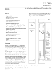
Five Slot, Rear Mount - IC697CHS750
Nine Slot, Rear Mount - IC697CHS790
Nine Slot, Front Mount - IC697CHS791
GFK-0079K
November 1999
PLC Racks
Five Slot, Rear Mount - IC697CHS750
Nine Slot, Rear Mount - IC697CHS790
Nine Slot, Front Mount - IC697CHS791 (Standard Racks - Front and Rear Mount)
datasheet GFK-0079K
CPU and I/O configurations. Each rack has provision
for one power supply at the leftmost module position;
and either nine additional slot locations (nine-slot
rack) or five additional slot locations (five-slot rack).
Features
H
H
Accepts all IC697 PLC module types
H
Front mount rack mounts in a standard 19I (480
mm) rack (fans normally not required)
H
H
Accepts plug-in AC or DC IC697 power supply
Rear mount racks mount in a 10I (254 mm) deep
enclosure (fans normally not required)
Overall rack dimensions are 11.15IH x 19IW x 7.5ID
(283mm x 483mm x 190mm) for the Nine-Slot Rack
and 11.15IH x 13IW x 7.5ID (283mm x 320mm x
190mm) for the Five-Slot Rack. Slots are 1.6I wide
except the power supply slot which is 2.4I wide.
Provision for two rack operation from single power supply
Two racks can be interconnected to share a single
power supply for applications having extendedI/O
requirements. A Power Supply Extension Cable kit
(IC697CBL700) is available for such applications.
NOTE: For Power Supply compatibility see page 5.
Functions
Each rack provides slot sensing for rack-type I/O modules designed for the IC697 PLC. No jumpers or DIP
switches on the I/O modules are required for module
addressing.
The Standard Nine-Slot Racks and the Five-Slot Rack
for the IC697 programmable controller are used for all
a44732
ÎÎ
01
9
8
4
2
SLOT
1
SLOT
2
SLOT
SLOT
3
1
4
SLOT
5
SLOT
6
SLOT
7
SLOT
8
ÎÎ
ÎÎ
Î
ÎÎ
ÎÎ
ÎÎ
ÎÎ
t
Series 90 -70 Programmable Controller Data Sheet Manual
GFK-0600F
4-1
PLC Racks
2
GFK-0079K
November 1999
Five Slot, Rear Mount - IC697CHS750
Nine Slot, Rear Mount - IC697CHS790
Nine Slot, Front Mount - IC697CHS791
Rack Outline Drawings
a42139
DIMENSIONS IN INCHES, MILLIMETERS ARE IN PARENTHESIS
WITH OPTIONAL VME J2
BACKPLANE KIT
1.00
(25.4)
* * 6.00
(152.4)
9.14
(232)
7.25
(184)
CONNECTOR
FOR
POWER
SUPPLY
SPACER
(QTY.4)
SIDE VIEW
ÏÏ
ÎÎ
ÏÏ
ÎÎ
ÏÏ
ÎÎ
ÏÏ
ÎÎ
ÏÏ
ÎÎ
ÏÏ
ÎÎ
ÎÎ
ÎÎÏÏÎÎ
CABLE
ENTRANCE
FROM
BOTTOM
I/O TERMINAL
RESTRAINING
STRAP
.75
(19)
6.75
(172)
* * * 6.00
(152.4)
18.11 11.71
(460) (297)
17.04 10.64
(433) (264)
*
REMOVABLE
I/O
TERMINAL
BLOCK
19.00 12.60
(483) (320)
.45
(11)
GROUND
STUD
Î Î
Î
Î
Î
Î
ÎÎ
Î
Î
Î
ÎÎ
Î
Î
Î
Î
Î
Î
Î
ÎÎ
Î
Î
Î
Î
Î Î
ÎÎ
Î
Î
Î
Î
Î
ÎÎ
Î
Î
Î
Î
Î
Î
Î
Î
Î
ÎÎ
Î
Î
Î
Î
Î
Î
Î
Î
Î
ÎÎ
Î
Î
Î
Î
Î
Î
Î
Î
Î
ÎÎ
Î
Î
Î
Î
Î
ÎÎ
Î
Î
Î
Î
ÎÎ
Î
Î
Î
Î
Î Î
ÎÎ
Î ÎÎÎÎÎÎÎ
ÎÎÎ
ÎÎÎÎÎ
POWER
SUPPLY
1
2
3
4
5
6
7
8
*
9
GROUND
STUD
11.50
(292)
11.15
(283)
.25 DIA.
(TYPICAL)
2.24
(57)
HINGED
DOOR
FRONT VIEW
* ALLOW SUFFICIENT HORIZONTAL CLEARANCE FOR ACCESS TO GROUND STUDS
AT EACH END OF THE RACK.
* * IF THE EXTENSION CABLE IS USED, ALLOW APPROXIMATELY 6 INCH HORIZONTAL
CLEARANCE ON THE LEFT SIDE OF THE RACK FOR ACCESS TO THE CONNECTOR.
* * * 6.00
(152.4)
* * * ALLOWANCE FOR COOLING (IF REQUIRED FOR ADDITIONAL COOLING, RACK FAN
ASSEMBLY (IC697ACC721 OR IC697ACC724) IS AVAILABLE ).
= DIMENSIONS FOR 5 SLOT RACK
Figure 1. Outline Drawing for Standard Rear (Panel) Mount Rack
a45171
DIMENSIONS IN INCHES, MILLIMETERS ARE IN PARENTHESIS
WITH OPTIONAL VME J2
BACKPLANE KIT
1.00
(25.4)
9.14
* * 6.00
(152.4)
(232)
7.25
(184)
REMOVABLE
I/O
TERMINAL
BLOCK
ÏÏ
ÎÎ
ÏÏ
ÎÎ
ÏÏ
ÎÎ
ÏÏ
ÏÏÎÎ
ÎÎ
ÏÏ
ÎÎ
ÎÎ
ÎÎÏÏÎÎ
CONNECTOR
FOR
POWER
SUPPLY
SPACER
(QTY.4)
SIDE VIEW
I/O TERMINAL
RESTRAINING
STRAP
CABLE
ENTRANCE
FROM
BOTTOM
HINGED
DOOR
.45
(11)
*
1.48
(38)
11.50
(292)
7.50
(191)
2.25
(57)
3.00
(76)
2.25
(57)
1.48
(38)
19.00 12.60
(483) (320)
18.34 11.94
(466) (303)
* * * 6.00
(152.4)
17.04 10.64
(433) (270)
ÎÎÎÎÎÎÎÎÎÎÎÎÎ
ÎÎÎ
ÎÎÎ
ÎÎ
ÎÎÎ
ÎÎÎ
ÎÎÎ
ÎÎ
ÎÎÎ
ÎÎÎ
ÎÎÎÎ
ÎÎÎ
ÎÎ
ÎÎÎÎÎÎÎÎÎÎÎÎÎ
ÎÎÎ
Î
ÎÎ
Î
ÎÎ
Î
ÎÎ
Î
ÎÎ
Î
ÎÎ
ÎÎ
ÎÎ
Î
ÎÎ
Î
ÎÎ
Î
ÎÎ
ÎÎÎÎÎÎÎÎÎÎÎÎÎ
ÎÎÎ
Î
ÎÎ
Î
ÎÎ
Î
ÎÎ
Î
ÎÎ
Î
ÎÎ
ÎÎ
ÎÎ
Î
ÎÎ
Î
ÎÎ
Î
ÎÎ
ÎÎÎÎÎÎÎÎÎÎÎÎÎ
ÎÎÎ
Î
ÎÎ
Î
ÎÎ
Î
ÎÎ
Î
ÎÎ
Î
ÎÎ
ÎÎ
ÎÎ
Î
ÎÎ
Î
ÎÎ
Î
ÎÎ
ÎÎÎÎÎÎÎÎÎÎÎÎÎ
ÎÎÎ
Î
ÎÎ
Î
ÎÎ
Î
ÎÎ
Î
ÎÎ
Î
ÎÎ
ÎÎ
ÎÎ
Î
ÎÎ
Î
ÎÎ
Î
ÎÎ
ÎÎÎÎÎÎÎÎÎÎÎÎÎ
ÎÎÎ
Î
ÎÎ
Î
ÎÎ
Î
ÎÎ
Î
ÎÎ
Î
ÎÎ
ÎÎ
ÎÎ
Î
ÎÎ
Î
ÎÎ
Î
ÎÎ
ÎÎÎÎÎÎÎÎÎÎÎÎÎ
ÎÎÎ
Î
ÎÎ
Î
ÎÎ
Î
ÎÎ
Î
ÎÎ
Î
ÎÎ
ÎÎ
ÎÎ
Î
ÎÎ
Î
ÎÎ
Î
ÎÎ
ÎÎÎÎÎÎÎÎÎÎÎÎÎ
ÎÎÎ
ÎÎÎ
ÎÎÎ
ÎÎÎ
ÎÎÎ
ÎÎÎ
ÎÎÎ
ÎÎÎ
ÎÎÎÎ
ÎÎ
ÎÎÎ
ÎÎÎ
GND
STUD
*
GND
STUD
11.15
(283)
.265 x .437
(TYPICAL)
FRONT VIEW
.33 (8.38)
* ALLOW SUFFICIENT HORIZONTAL CLEARANCE FOR ACCESS TO GROUND STUDS
AT EACH END OF THE RACK.
* * IF THE EXTENSION CABLE IS USED, ALLOW APPROXIMATELY 6 INCH HORIZONTAL
CLEARANCE ON THE LEFT SIDE OF THE RACK FOR ACCESS TO THE CONNECTOR.
* * * 6.00
(152.4)
* * * ALLOWANCE FOR COOLING (IF REQUIRED FOR ADDITIONAL COOLING, RACK FAN
= DIMENSIONS FOR 5 SLOT RACK
ASSEMBLY (IC697ACC721 OR IC697ACC724) IS AVAILABLE).
Figure 2. Outline Drawing for Standard Front (Rack) Mount Rack
4-2
t
Series 90 -70 Programmable Controller Data Sheet Manual
GFK-0600F
PLC Racks
3
GFK-0079K
November 1999
Five Slot, Rear Mount - IC697CHS750
Nine Slot, Rear Mount - IC697CHS790
Nine Slot, Front Mount - IC697CHS791
Rack Mounting
The rack must be mounted in the orientation as
shown in Figures 1 and 2. Sufficient space must be
left around the rack as shown to allow air flow for
module cooling. The mounting requirements (either
front or rear mount) must be determined according to
the application and the proper rack ordered. Mounting flanges are an integral part of rack side panels and
are installed at the factory.
A Rack Fan Assembly is available for mounting on the
Nine-Slot Racks when required for installations where
heat buildup could be a problem. The Rack Fan Assembly is available in three versions:
H
H
H
IC697ACC721 for 120 VAC power source
IC697ACC724 for 240 VAC power source
IC697ACC744 for 24 VDC power source
Refer to GFK-0637C, or later for detailed information
about the Rack Fan Assembly.
I/O Connector
These racks accommodate rack-type IC697 high-density I/O modules, which use a detachable field wiring
terminal board. Each I/O module will accept up to
forty AWG #14 (2.10mm2) wires. The wire bundle is
routed out the bottom of the terminal board cavity
where a cleat is provided for a tie wrap to secure the
bundle to the terminal board housing.
Mechanical Keying
IC697 I/O modules are mechanically interlocked by
means of a key to prevent inadvertent interchange of
one module type for another (for example, AC type
for DC type). A key unique to each module type is
included with the module.
When the module is inserted into the rack, the key
automatically latches onto the center rail of the rack,
where it remains when the module is extracted. Only
the correct module type can then be inserted into that
rack slot.
If it is necessary to change the module location in the
rack after the key has been latched onto the center rail
of the rack, the key can be removed by pushing it upward to unhook the latch while pulling it off the rail.
It may then be reinserted onto the module and the
module inserted into the rack in the desired location.
t
Series 90 -70 Programmable Controller Data Sheet Manual
GFK-0600F
Note
The power supply slot is unique - only the
power supply can be installed in the leftmost rack position.
Power Supply Extension Cable
For many applications, one power supply can provide
the power requirements of two racks. Such dual-rack
operation from a single power supply can be implemented if only 5 volt power of 5.2 amperes or less is
required in the second rack.
A 3-foot (1 meter) Power Supply Extension Cable is
available (see the Ordering Information on the last
page of this data sheet) which provides the necessary
interconnection. In addition to +5 volt power, the
extension cable includes power sequencing signals
necessary for proper system operation.
The Power Supply Extension cable attaches to a 9-pin
D type connector located on the backplane. Access to
the connector is via a hole in the left side of the rack as
shown in the outline drawing. Adequate clearance
(approximately 6 inches 152.4mm) ) must be provided
on the left side of the rack for access to the connector.
The Power Supply Extension cable must be secured
before power is applied. It must not be disconnected
during system operation.
Slot Addressing
The IC697 PLC system allows user configuration of
I/O point references for modules in a rack without the
need for board address DIP switches or jumpers. The
address structure is described in the applicable Programmable Controller Installation Manual. Configuration
is done with the MS-DOSr or Windowsr programming software configurator function. For more information on configuration, see the applicable Programming Software User’s Manual.
Rack Number
Multiple racks in a system must be assigned a rack
number from 0 to 7; the CPU rack is always Rack 0.
The PLC determines the number of each rack in the
system from four binary-encoded jumpers on the
rack’s backplane. These jumpers are located on the
backplane directly behind the power supply, which
must be removed to gain access to the jumpers.
4-3
PLC Racks
4
GFK-0079K
November 1999
Five Slot, Rear Mount - IC697CHS750
Nine Slot, Rear Mount - IC697CHS790
Nine Slot, Front Mount - IC697CHS791
r MS-DOS and Windows are registered trademarks of Microsoft Corporation.
To set the rack number, move the jumpers correSystem Noise Immunity
sponding to 1, 2, 4, and 8 bits to either the 0 or 1 position. The sum of the digits in the 1 position equals the
Three easy steps must be taken to properly ground
desired rack number. For example, rack number 2
the IC697 programmable controller system to reduce
would have the 1, 4 and 8 bit jumpers in the 0 position
the possibility of errors due to electrical noise.
and the 2 bit jumper in the 1 position as shown below.
1. Make sure that the power supply mounting
screws, especially the bottom two, are properly
secured.
a42823
ÎÎ
ÎÎ
ÎÎ
2. The GND terminal on the power supply must be
connected to the GND terminal on either side of
the rack using AWG #12 (3.33 mm2) wire. Use of a
ring terminal and star washer is recommended.
01
3. The GND terminal on the rack must be connected
to a good earth ground.
8
4
RACK NUMBER =2
2
1
Module Retention
IC697 I/O modules have molded latches that automatically snap onto the upper and lower rails of the rack
when the module is fully inserted. Optionally, M2.5x8
screws may be used to secure the modules to the rack
for high vibration applications.
Figure 3. Rack Number Jumpers
Warning
Safety Ground
The ground lug on either side of the rack must be connected to earth ground with not less than an AWG
#12 (3.33mm2) wire. The ground lugs are #8-32.
Warning
If the ground lug is not connected to earth
ground, the rack is not grounded. The
rack must be grounded to minimize electrical shock hazard which may result in
severe personal injury.
Shield Ground
The bottom rail of the rack is used for module shield
grounding. Some IC697 I/O modules have a ground
clip that contacts the conductive bottom rail when the
module is fully inserted. Shield connections in the
user connectors are routed to this ground clip via conductors on the module.
4-4
Do not remove (or insert) modules when
either the programmable controller power
supply or any externally-connected power
sources are on. Hazardous voltages may
exist. Personal injury, damage to the module or improper operation of the device or
process being controlled may result.
To remove an IC697 module, first remove the field
half of the terminal board (if it is an I/O module), then
grasp the top and bottom of the module to depress
the latch releases while pulling the module out. For
more detailed information on removing I/O terminal
boards, refer to the applicable Programmable Controller
User’s manual or individual data sheets for I/O modules.
If M2.5x8 screws have been used to secure modules to
the rack, remove the screws before removing the
modules.
A blank faceplate is available to cover unused slots in
the rack. See the Ordering Information on page 5.
t
Series 90 -70 Programmable Controller Data Sheet Manual
GFK-0600F
PLC Racks
5
GFK-0079K
November 1999
Five Slot, Rear Mount - IC697CHS750
Nine Slot, Rear Mount - IC697CHS790
Nine Slot, Front Mount - IC697CHS791
Table 1. Specifications for Standard Racks, IC697CHS750/790/791 [
Number of Slots
5 or 9, plus power supply slot
Maximum 5 Volt Current
20 amps (100 watt 120/240 VAC or 125 VDC power supply)
11 amps (55 watt 120/240 VAC or 125 VDC power supply)
18 amps (90 watt 24 VDC power supply)
18 amps (90 watt 48 VDC power supply)
Current Required from I/O Bus
0.5 amps
I/O References
User configurable without the use of module jumpers or DIP switches.
Rack Identification
Four jumpers behind rack power supply
Dimensions
Nine Slot Rack
Height
11.15”
283mm
Five Slot Rack
VME
Width
19.00”
483mm
Depth
7.5”
190mm
11.15”
12.6”
7.5”
283mm
320mm
190mm
All modules for the IC697 I/O system extend 1.7” (43mm) beyond the front of the rack.
System designed to support the VME standard C.1
[ Refer to GFK-0867B, or later for product standards and general specifications.
Table 2. Ordering Information
Description
Catalog Number
Rack , Five-Slot, rear mount
IC697CHS750
Rack, Nine-Slot, rear mount
IC697CHS790
Rack , Nine-Slot, front mount
IC697CHS791
Power Supply Cable Kit (includes cable and faceplate for vacant power supply slot)
IC697CBL700
Blank Faceplate Slot Filler (quantity 6)
IC697ACC720
Rack FanAssembly, 120 VAC (optional)
IC697ACC721
Rack FanAssembly, 240 VAC (optional)
IC697ACC724
Rack FanAssembly, 24 VDC (optional)
IC697ACC744
Note: For Conformal Coat option, Low Temperature Testing option, or Severe Vibration option please consult the factory for
price and availability. Racks for use in Severe Vibration environments include heavy duty side mount plates.
Power Supply Compatibility With Rack Versions
The IC697 standalonepowersupplies can only be mounted on the IC697 racks having the catalog numbers listed
below.
H
IC697CHS790D (Nine-Slot, rear mount) and IC697CHS750C (Five-Slot, rear mount)
The catalog numbers for the standalone power supplies affected by this restriction are:
H
H
H
H
IC697PWR721 (24 VDC, 90W Power Supply with Power Supply Adapter)
IC697PWR722 (24 VDC, 90W Power Supply Module)
IC697PWR731 (125 VDC, 60W Power Supply with Power Supply Adapter)
IC697PWR732 (125 VDC, 60W Power Supply Module)
All plug-in IC697 power supplies can be installed in any version of the IC697 racks.
t
Series 90 -70 Programmable Controller Data Sheet Manual
GFK-0600F
4-5