1
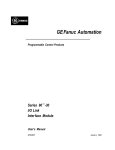
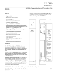
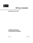
This Datasheet for the
IC697BEM721
I/O Link Interface Module for the Series 90-70.
http://www.cimtecautomation.com/parts/p-14754-ic697bem721.aspx
Provides the wiring diagrams and installation guidelines for this GE Series 90-30
module.
For further information, please contact Cimtec Technical Support at
1-866-599-6507
[email protected]
1
Bus Expansion Modules
IC697BEM721
66
GFK-0645C
August 1997
I/O Link Interface Module
I/O Link Interface Module (IC697BEM721)
datasheet GFK-0645C
Module Features
a45005
D IC697 PLC interface to CNC-compatible serial I/O
link.
D I/O Link master or slave.
D Occupies single slot in PLC rack.
MODULE OK
LINK ACTIVE
LINK CFG
D Three status LEDs
D I/O Link reset pushbutton.
I/O LINK
D 1.5 MHz serial port transmission rate.
Overview
The Fanuc I/O Link is a serial interface that provides
high-speed exchange of I/O data between a master
device and up to 16 slaves. The maximum distance
between individual devices on an I/O Link is 10 meters
(33 feet). If greater distances are required between
modules, optional fiber optics cable and Optical
Adapters can be used to increase the maximum distance
between individual devices to 100 meters (330 feet).
Up to four I/O Link Interface Modules can be installed
in an IC697 PLC. Each I/O Link Interface Module can be
used in either master or slave mode. Usually, when
there are multiple I/O Link Interface Modules in the
same PLC, they are on separate I/O Links. However, it
is possible to have more than one I/O Link Interface
Module in the IC697 PLC connected to the same link, if
that suits the needs of the application.
When used as a master, an I/O Link Interface Module
can exchange up to 1024 discrete inputs and 1024
discrete outputs with slave devices. Potential slaves
include the IC693 PLC, Series 0 CNC, and Power Mate
CNC.
When used as a slave, the IC697 I/O Link Interface
Module can exchange up to 64 discrete inputs and 64
discrete outputs with the master. The master may be
another IC697 PLC, a Series 15, Series 16, or Series 18
CNC, a Series 0 Model C CNC, or an F-D Mate CNC. The
IC697 PLC and Series 0 CNC can be used as either
master or slave.
The I/O Link Module is configured using the MS-DOSr
programming software. Application software, supplied
on diskettes with the I/O Link Module, can be used to
set up and control the I/O Link. This application
software can also be used to assign the location of the
input and output data to and from the I/O Link, and to
provide diagnostics capabilities for the I/O Link. The
MS-DOS programmer is used to integrate this
application software with the rest of an application
program.
r MS-DOS is a registered trademark of Microsoft Corporation.
t
Series 90 -70 Programmable Controller Data Sheet Manual
GFK-0600F
66-1
Bus Expansion Modules
2
GFK-0645C
August 1997
I/O Link Interface Module
Module Description
Reset Pushbutton
The I/O Link Interface Module occupies one slot in the
IC697 PLC rack. It can be installed in any rack, in any
slot except slot 1, which is reserved for the CPU module.
The Reset pushbutton provides a convenient means of
reset if a failure occurs. If the module is being used as a
master, pushing the Reset button resets both the
module and operation of the link. The application
program must be used to re-initialize the link. If the
module is being used as a slave, pushing the Reset
button resets the module, if a fault has caused the
module to stop operating while the rest of the link
continues to function.
a45015
MODULE OK
LINK ACTIVE
LINK CFG
RESET
PUSHBUTTON
ÎÎ
ÎÎÎ
Î
Î
Î Î
Î
BEM 721
MODULE OK
LINK ACTIVE
LINK CFG
ON OR BLIN K = OK
PUSH TO RESET
I/O LINK
INTERFACE
MODULE FUNCTION
ÎÎ
ÎÎ
MODULE OK
LINK ACTIVE
LINK CFG
ON OR BLIN K = OK
PUSH TO RESET
I/O LINK
INTERFACE
MODULE FUNCTION
SERIAL I/O LINK
INTERFACE
SERIAL I/O LINK
INTERFACE
: MASTER MODE
: MASTER MODE
: SLAVE MODE
RS-422/485
SERIAL PORT
RS-422/485
SERIAL PORT
NEXT
(JD1A)
NEXT
(JD1A)
PREVIOUS
(JD1A)
RS-422/485
SERIAL PORT
RS-422/485
SERIAL PORT
NOT
USED
NOT
USED
NEXT
(JD1A)
RS-422/485
CONNECTOR
RS-422/485
CONNECTOR
MODULE
IC697BEM721
LABEL
44A726758-125R01
Serial Ports
BEM 721
MODULE
IC697BEM721
LABEL
44A726758-126R01
The front of the I/O Link Interface Module has two
20-pin, D connector, RS-422/485 serial ports. These
ports are used for connection to the Fanuc I/O Link.
Application Software
The IC697 I/O Link Interface Module is provided with
an application software diskette. Program logic on the
diskette can be used to integrate up to four I/O Link
Interface Modules into the PLCs application program.
It will transfer I/O data between the module and the
PLC, perform diagnostics functions, and transfer
application program commands to the module.
Additional application program logic can be created to
perform the following functions:
1. To specify the number of I/O Link Interface Modules
present in the PLC.
2. To specify, for each I/O Link Interface Module:
A. A rack and slot location.
B. Master or slave operation.
3. And, for each I/O Link Interface Module that will be
a master:
LEDs
The module has three LEDS that show its operating,
configuration, and communications status.
Module OK:
indicates the module’s operating
status.
Link Active:
indicates the module’s
communications status.
Link Cfg:
indicates whether I/O Link
configuration has occurred.
66-2
A. To assign a data length and I/O addresses for
each slave on its link.
B. To control operation of the link and monitor
module and link status.
The I/O Link Interface Module User’s Manual (GFK-0644),
chapter 4, explains how to add logic for I/O Link
Interface Modules to an application program.
t
Series 90 -70 Programmable Controller Data Sheet Manual
GFK-0600F
Bus Expansion Modules
3
GFK-0645C
August 1997
I/O Link Interface Module
Module Installation
The I/O Link Interface Module can be installed in any
rack, in any slot except slot 0, which is reserved for the
CPU module. The only placement restriction is the
module not be located to the left of any board that
generates interrupts (such as a PCM, IC66* Bus
Controller, Analog, Factory LAN, or Ethernet module).
LED
Status
Module
OK
Caution
Rack power MUST be OFF when installing
or removing the I/O Link Module.
Link
Active
1. Grasp the module firmly with your hand and insert
it into the card guide.
2. Align the module’s printed circuit board with the
connector on the rack backplane and slide it towards
the connector until it has started to seat.
3. Place one thumb on the left side of the top plastic
flange and the other thumb on the left side of the
bottom plastic flange. Push the board into the
connector until the top and bottom latches click onto
the rack rails.
4. Visually inspect the board to be sure it has seated
properly.
Caution
Link Cfg
LED
Status
Indication
On
The I/O Link Module has
passed its powerupdiagnostics
and the hardware is operating
properly.
OFF
The module has failed a
diagnostic test, or a run-time
failure has been detected.
Blinking
The module is running powerup
diagnostics.
On
The module is ready to communicate with the I/O Link.
OFF
A failure has occurred with the
I/O Link, and communications
are not possible.
Blinking
The module is transferring data
on the I/O Link.
ON
I/O Link configuration has
occurred, and the module is
ready to communicate.
OFF
The module has not been configured for link operation.
Module Removal
1. Remove power from the rack.
2. Grasp the module firmly at the top and bottom of
the board cover, with your thumbs on the front of
the cover, and your fingers on the plastic clips on the
back of the cover.
Make sure no exposed wiring touches any
conductive material. Such contact could
damage the module, and other units to
which it is connected.
3. Squeeze the rack clips on the back of the cover to
disengage the clips from the rack rail.
5. A CPU module must be present in rack 0 slot 1 before
applying power to the I/O Link Interface Module. Turn on
power, and observe the LEDs.
5. Slide the board along the card guide and remove it
from the rack. Avoid contact with neighboring
boards and wiring.
t
Series 90 -70 Programmable Controller Data Sheet Manual
GFK-0600F
4. Pull the module firmly to remove it from the
backplane connector.
66-3
Bus Expansion Modules
4
GFK-0645C
August 1997
I/O Link Interface Module
Cable Types for the I/O Link
The following cables and connectors can be used to complete the I/O Link between devices.
Item
Catalog Number
Vendor
Description
Cable
A03B-0807-K801
[
5 meter length with connectors on both ends. Connects
between master and slave device, or between two slave
devices.
Cable
A03B-0807-K802
[
10 meter length with connectors on both ends.
Connects between master and slave device, or between
two slave devices.
Cable
AMW 2076
Connector
A02B-0120-K301
Connector
PCR-E20FS
Honda
20-pin female connector with solder lug.
PRC-V20L
Honda
Connector cover.
OKI Electric Cable
10-pair shielded cable without connectors, for making
custom-length cable. Connects between master and
slave device, or between two slave devices.
[
20-pin connector with solder lug. Consists of the two
followingparts.
Cable
A03B-0807-K803
[
1 meter length with connectors on both ends.
Connects between master or slave and Optical Adapter.
This cable can only be used with an Optical Adapter; do
not use it for master/slave or slave/slave connections.
Optical Adapter
A138-154-B001
[
Required for optical fiber cable.
Cable
A66L-6001-009
[
Optical fiber cable for use with Optical Adapter.
” #L10R03
10m
” #L15R03
15m
” #L20R03
20m
” #L30R03
30m
” #L40R03
40m
” #L50R03
50m
” #L60R03
60m
” #L80R03
80m
” #L90R03
90m
” #L100R03
100m
[ See your local PLC distributor or local sales office for purchasing information.
66-4
t
Series 90 -70 Programmable Controller Data Sheet Manual
GFK-0600F
Bus Expansion Modules
5
GFK-0645C
August 1997
I/O Link Interface Module
I/O Link Connection
a45018
The devices on an I/O Link must be installed in the order
expected by the master. If the IC697 PLC is the master,
be sure to connect the devices on a link in the order that
agrees with the information provided to the application
Program Block.
JD1B
JD1A
JD1A
JD1B
Using the appropriate cable, connect the devices on the
link. Notice that the cables are marked JD1A on one end
and JD1B on the other.
The functions of the ports on the I/O Link Interface
Module depend on whether the module is used as a
master or as a slave. Refer to the illustrations below.
Serial Port Pin Assignments
I/O Link Module Used as a Master
If the module will be used as a master, connect the cable
from the first slave to the upper port. The lower port is
not used in master mode.
a45017
JD1A
JD1B
JD1B
NOT
USED
Pin #
Signal
Pin #
Signal
1
2
3
4
5
6
7
8
9
10
SIN
*SIN
SOUT
*SOUT
11
12
13
14
15
16
17
18
19
20
0 volts
0 volts
0 volts
0 volts
0 volts
0 volts
+5 volts
+5 volts
+5 volts
The +5-volt output from each connector powers the
fiber optic link modules for long distance applications.
The +5-volt output is not used otherwise.
Caution
I/O Link Module Used as a Slave
If the module will be used as a slave, connect the cable
from the previous device (either the master or another
slave) to the upper port. If the module is followed by
another slave on the link, connect the cable from that
device to the lower port.
t
Series 90 -70 Programmable Controller Data Sheet Manual
GFK-0600F
Do not use a cable that includes the +5 volt
line (cable A03B-0807-K803) to directly
connect I/O Link devices. Damage to the
equipment may result.
If the link includes Optical Adapters and fiber optic
cables, please refer to the I/O Link Interface Module User’s
Manual for installation instructions.
66-5
Bus Expansion Modules
6
GFK-0645C
August 1997
I/O Link Interface Module
Module Specifications [
Physicaldimensions:
6.3in x 9.19in (160mm x 233mm). Single slot in IC697 rack.
Module type:
IC697 PLC module, providing I/O Link communications with
up to 16 slave devices in master mode.
Current requirement from +5-volt bus
1.0 Amp without Optical Adapter.
0.2 Amps per Optical Adapter.
LEDs:
Module OK, I/O Link Active, I/O Link Configured
Pushbutton:
ResetI/OLink
Configuration:
In master mode
Controls up to 16 slaves
Choice of 32 or 64 inputs/outputs per slave.
In slave mode
Controlled by one master
Choice of 32 or 64 inputs/outputs
I/O Points:
In master mode
1024 inputs, 1024 outputs maximum
(64inputs/outputsperslavemaximum)
In slave mode
64 inputs, 64 outputs maximum
PLC capacity (examples; for further details, refer
to the I/O Link Module User’s Manual):
781 CPU
Up to four I/O Link Modules
771 CPU
Up to two I/O Link Modules
731 CPU
One I/O Link Module
RS-422/485 Serial Ports:
1.5 MHz transmission rate.
[ Refer to GFK-0867B, or later for product standards and general specifications. For installations requiring compliance to more
stringent requirements (for example, FCC or European Union Directives), refer to Installation Requirements for Conformance to
Standards.
Note: For Conformal Coat option, or Low Temperature Testing option please consult the factory for price and availability.
For More Information,
Please refer to these related publications:
I/O Link Module User’s Manual (GFK-0644).
Programmable Controller Installation Manual (GFK-0262).
Programming Software User’s Manual (GFK-0263).
Programmable Controller Reference Manual (GFK-265).
66-6
t
Series 90 -70 Programmable Controller Data Sheet Manual
GFK-0600F