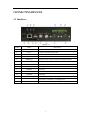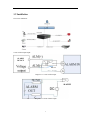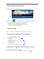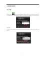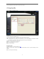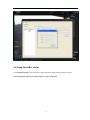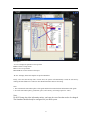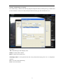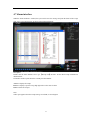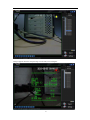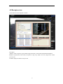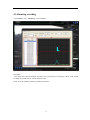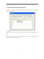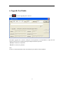
1
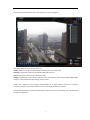
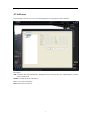
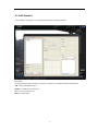
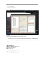
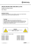
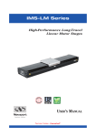
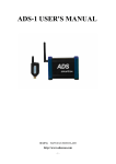
Intelligence POS Surveillance System
Smartbox User Manual
Table of Contents
1. CONNECTING DEVICES.................................................................... ERROR! BOOKMARK NOT DEFINED.
1.1 Interfaces ........................................................................................................................................................ 2
1.2 Installation ...................................................................................................................................................... 3
2. SOFTWARE INSTALLATION ............................................................................................................................. 4
3. QUICK GUIDE ....................................................................................................................................................... 4
3.1 Quick guide for applying monitoring function: .............................................................................................. 4
3.2 Quick guide for applying receipt format inquiry function: ............................................................................. 4
4. OPERATION ........................................................................................................................................................... 5
4.1 Login ............................................................................................................................................................... 5
4.2 Add users ........................................................................................................................................................ 7
4.3 Add channels ................................................................................................................................................... 8
4.4 Add DVR device .............................................................................................................................................. 9
4.5 Setup SmartBox ............................................................................................................................................. 10
4.6 Setup SmartBox alarm .................................................................................................................................. 11
4.7 Alarm interface ............................................................................................................................................. 14
4.8 Receipts review ............................................................................................................................................. 16
4.9 Alarm log searching ...................................................................................................................................... 17
5. RECEIPT DATA TRANSMISSION SIMULATION ......................................................................................... 18
6. UPGRADE TOOL GUIDE ................................................................................................................................... 19
7. FAQ ........................................................................................................................................................................ 20
1
CONNECTING DEVICES
1.1 Interfaces
Diagram 1.1
Number
Name
1
DC/12V
interface for direct current 12 volt
2
LAN
to connect with the network cable
3
USB
USB interface
4
SD
5
VIDEO IN
6
VIDEO OUT
7
COM1
input/output interface
8
COM2
input/output interface
9
POWER
power state
10
STATUS
system running state
11
ALARM
alarm lamp
12
ALARM IN
13
ALARM OUT
14
DEBUG
Description
SD card interface
inputting interface connected with camera, BNC interface
video outputting interface
alarm input(4 interfaces)see Diagram 1.1
alarm output(2 interfaces)see Diagram 1.2
debug interface
2
1.2 Installation
The correct installation:
Circuit of alarm input/output:
ALARM
DEVICE
RELAY
Diagram 1.1: Circuit of alarm input
ALARM
Diagram 1.2: Circuit of alarm output
3
2. SOFTWARE INSTALLATION
In first installation, please set up “IMS1000_setup.exe” as illustrated in next diagram:
IMS1000-POS icon:
will be created automatically on your desktop when you finish the installment.
Note: to run the “cmd” program in “db” file when database connecting is fail.
1. to double click: uninstallAndStartMYSQL.cmd for data release
2. to double click: installAndStartMYSQL.cmd for database installation
3. to double click: initdatabase.bat for initialization
3. QUICK GUIDE
After connecting the device and installing the software, follow the quick guide below.
3.1 Quick guide for applying monitoring function:
1. Correctly login “IMS1000-POS”
To install hardware & software and login, see 1/2/4.1
2. To add SmartBox
To add SmartBox device in “SmartBox” interface, see 4.5
3. To add organizational region
To add organizational region in “Region” interface, see 4.3
4. To set DVR and channel:
To add DVR and connect channel with SmartBox, see 4.4
3.2 Quick guide for applying receipt format inquiry function:
1 To connect the DVR channel and device, see 4.4
2 To Set receipt formats and alarm condition in device configuration interface, see 4.6
4
4. OPERATION
4.1 Login
Double click the
icon to start the Smartbox software. When it is your first time to login, please
use “system” as the username and password, and the user will login as the administrator. See the next diagram.
Description:
Click “OK” to log in directly and check the last login time if the “Remember” option is ticked. See the next
diagram.
5
You will enter the main interface after successful login, see the next diagram:
Description: there are four zones to be aware of:
Alarms: alarm list to display alarm information including the receipt information
Channels: a channel list of all associated DVRs and Smartbox devices
Search: search past recorded receipts, alarms and video
Settings: set parameters of all associated functions of the client software. Such settings include adding DVRs,
setting up various Smartboxes and setting up receipt formats.
Double click a channel in list or drag the selected channel to an empty window preview box to play the
real-time surveillance video. Please reference section 4.4 in adding a DVR to the software.
The information displaying on bottom left hand side is: real-time video screen switching, time, CPU utilization,
username and login time.
6
4.2 Add users
Click “Settings” and enter the “User” tab; add management users and operators in this interface:
Description:
Add: to add new users that classified into “Management type” and “Operator type”. Duplicating the username
again is not allowed.
Modify: to modify the users’ information.
Save: to save users’ information
Delete: delete the user selected
7
4.3 Add channels
Click “Settings” and “Region” to edit organizational region in following interface:
Description:
The organizational region can add new categories to organize several different DVRs and Smartboxs.
Add: to add organizational region
Modify: to modify the selected region
Save: to save region parameter
Delete: to delete region
8
4.4 Add DVR device
Click “Settings” and “Region” to add DVR in following interface:
Description:
Choose one of the organizations in ‘A’ area and set DVR in ‘B’ area.
‘B’ area: illustrate the operations of DVR which include adding, modifying, deleting, synchronization time,
testing DVR connection and setting equipment parameters. Choose channel buttons to select the channels and
display related information in A, B, C and D area.
Sync: DVR time in-sync with Smartbox system
Test: to check whether DVR is available over its network connection
Advance: configuration information
Add: to add DVR device
Modify: to modify the selected DVR device
Save: to save device parameter
Delete: to delete device
‘C’ area: to set the channels’ detail information
Link: to connect with SmartBox
Save: to save channels and devices setting
9
‘D’ area: SmartBox list which could be connected with channel
4.5 Setup SmartBox
Click “SmartBox” in “Settings” to set it:
Description:
‘A’ area: to illustrate the SmartBox devices
‘B’ area: the operation options of SmartBox include added modified and deleted
Add: to add SmartBox devices. Make sure all information is correct while inputting its information. Confirm
the IP address, port number, and the username/password to login to that Smartbox.
Modify: to modify SmartBox device parameter
Save: to save SmartBox device parameter
Delete: to delete parameter
Presentiment setting:
Condition Setting: to set alarm condition, see 4.6
Setup: to set ports’ alarm, setting the alarm type, port name which is refers to a specific meaning. See next
diagram.
Save: to save the ports’ alarm setting
10
4.6 Setup SmartBox alarm
Click Condition Setting to enter the interface which includes the alarm settings and format settings.
In first using, please click the “Format Setting” to set the receipt form:
11
Description:
‘A’ area: to display the parameter of receipt form
Clear: to delete receipt format
Save: to save receipt format
Save to All: to save the format to all receipts
‘B’ area: to display latest and complete receipt from Smartbox
Firstly, select the start and stop lines of items in B, the system will automatically records the selection by
clicking the related button in A. Then set other detail information and save the setting.
Note:
1. The red means the start and stop lines of the goods and the blue means the detail information of the goods.
2. To set the start and stop lines, goods name, price, total correctly. (select longer space for “total”)
Note:
Do NOT change the ticket information unless you know the exact lines that need to be changed.
The Smartbox should already be configured for your POS system.
12
Click the ‘Alarm Setting’ to set alarm:
The “alarm setting” is shown in the following diagram. Prompt the alarm by choosing the type, condition and
set value of alarm to. The user can add, modify and delete the alarm types, then click button to save.
Description:
Add: to add alarm types which display on list
Modify: to modify alarm condition
Delete: to delete selected items in list
OSD Display Mode: to set the parameter like font, color, position and overlying, click “save ” to complete the
operation.
Save: to save the current OSD setting
Close: to close all interfaces
13
4.7 Alarm interface
When the alarm condition is reached, the system will receive the message and print the detail of the receipt,
click “List” to get “Receipt List” as shown in the following diagram:
Description:
Double click the alarm numbers area to get 【Receipt List】interface. All the detail receipt information is
illustrated here.
The number on the top left shows the external port alarm number.
A area: to display all receipts.
B area: to display a specific receipt, high light refers to the cause of alarm.
Clear: to delete all receipts
Note:
Yellow spot appears when the receipts storage exceed 3M, see next diagram:
14
Red spot appears when the receipts storage exceed 3.8M, see next diagram:
15
4.8 Receipts review
Click “Search” to enter “Playback” interface:
Description:
A area: to search receipts by region, channel, begin & end time, record, alarm and download information
B area: to playback the video records, the options are play, stop, capture, slow, fast, single frame, normal,
previous, next.
C area: to display the detail of receipt record
16
4.9 Alarm log searching
Click ‘Search’ to enter “Alarm Log”, see next diagram
Description:
A area shows the connected channels and alarm type (receipt alarm or external port alarm); count amount
according day, month and year; list the historical record.
B area shows the searching results by bar chart and line chart.
17
5. Receipt Data Transmission Simulation
Simulation software helps to simulated operate without ZN-IV1000P-E device. The interface of simulation as
illustrated in next diagram:
Description:
To send receipts by COM port, click “Start” to test. Receipt amount and time will be listed. Click “Stop” to
cancel.
Note:
In “Send by COM” mode, connect PC with ZN-IV1000P-E device by serial port cable, and confirm the port
numbers of program and PC are accordant
18
6. Upgrade Tool Guide
Click
to run the “Upgrading Tool” interface:
Description: upgrade tool is used for setting the network parameter of ZN-IV1000P-E to adapt the local
network. Login the device, inputting the IP, port and password before operation.
【Read】to read the device parameter
【Write】to set the device parameter
Note:
The device would automatically restart when modify the port number of ZN-IV1000P-E.
19
7. FAQ
Q: There is no picture on the screen?
A: Ensure the “VIDEO OUT” and “VIDEO IN” on the Smartbox device is linked correctly and make sure the
power is on.
Q: How do you connect to a channel on a DVR through the software?
A: Be sure you added a DVR to the device list and all information is correct. Double click the monitored
channel which is on the information bar that is on the bottom of the interface or drag the selected channel to
the monitored area.
Q: Remote surveillance is not working?
A: Ensure that the IP, port number, username and password are set correctly for the DVR you are trying to
remotely view. Click “Test” to confirm the DVR device is available.
Q: The receipt is not overlaid on the video through the Smartbox device?
A: Test the procedure by the simulation software. How to use the simulation software can be found in chapter
5.
Q: The receipt is not overlaid on the video when running through the simulation tool.
A: Complete the installation; there is a “Receipts” folder in main directory of the software client. Ensure the
folder exists and is not empty.
Q: The receipt is not overlaid in the video when playback by “searching the receipt”?
A: Assure that the channel you are using with the DVR and Smartbox are synced. Check to be sure you are
searching for the correct time and date that the receipt occurred on.
Q: Receipt alarm is not displayed in list?
A: Ensure the receipt format is correct and that the Smartbox picked up the receipt as an alarm.
20