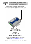
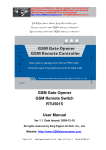
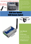
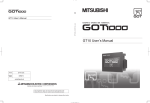
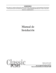
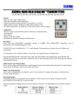
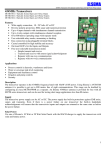
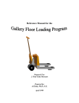
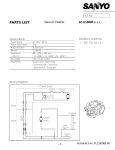
1
ELSEMA
GSM Receiver with relay output, GSM-1000
GSM-1000
GSM receiver with relay output for opening sliding and swing gates and doors or switching devices
Features
Switches relay with free call from mobile phone
Only authorised numbers can operate the GSM-1000
No call charges
Operates from anywhere if GSM network is available. Unlimited range!
Ignores unauthorised numbers
Authorised numbers easily entered by SMS command
2 digital inputs for sensors or switches.
SMS confirmation of relay switching.
Secure. Password protected
12 Volts DC power pack included
Application
Open/close gates, doors, shutters, garage doors with a free call!
Security alarm, On/Off lights, pumps and machines.
Description
The GSM-1000 works on latest GSM technology. All you need is to insert a valid SIM card and program phone
numbers of all users through simple SMS text commands. When an authorised user makes a call to the receiver,
it rejects the call after a single ring and activates a relay. Since the call is rejected, the user is not charged for the
call.
There are 2 digital inputs available which can be wired to motion sensor (PIR), door switch, windows or any
other type of NO (normally open) switch. The GSM-1000 can be programmed to send different SMS messages
for each input. (e.g. a reed switch from the kitchen window is wired to input 1 which will send an SMS message
“Kitchen Window” when activated and a motion sensor (PIR) in you bedroom is connected to input 2 which
will send a message “Bedroom” when activated.)
A 12V output is also available on the GSM-1000 which can activate a 12VDC siren or warning light when the
either of the inputs are activated. (Refer to the wiring diagram)
The GSM-1000 works on GSM network therefore the receiver can be activated from anywhere in the country
where GSM network is available. For example you can open your gate or switch on your kitchen lights in
Sydney from Melbourne by making a call from your mobile phone and without getting charged.
12 Volts DC Power Pack Included
Page 1
www.elsema.com
ELSEMA
GSM Receiver with relay output, GSM-1000
Technical Data
Power Source
12 Volts DC
GSM Frequency
Output
900/1800MHz
Common (C) and Normally Open (NO) relay outputs rated at 3A, 240VAC.
Shipping Weight
Dimensions
500 grams
120 x 90 x 25 mm.
Safety Instruction
Safe startup
Do not use the GSM-1000 in places where GSM equipment is prohibited or might bring
disturbance or danger
Interference
Wireless equipment might interfere GSM network signals of the GSM-1000 and influence its
performance.
Avoid using at Gas Stations
Do not use GSM-1000 at a gas station. Power off the unit when near fuels or chemicals
Avoid using near blasting areas
Please follow relevant restrictive regulations. Avoid using the device in blasting places.
Reasonable Use
Please install the product at a suitable place as described in this manual. Avoid signal shielding by
covering the mainframe.
Maintenance
All wiring and maintenance should be carried out only by qualified maintenance personnel.
Page 2
www.elsema.com
ELSEMA
GSM Receiver with relay output, GSM-1000
Setup and Programming Instructions
1. Caller ID has to be enabled so that the GSM-1000 knows who's calling.
2. Insert the SIM card into the GSM-1000.
3. The default password is 1234.
4. All settings are through SMS commands, please type the relevant SMS commands in your cell phone
and send to the GSM-1000 controller SIM number.
5. Relay 1 switches ON for the programmed time (factory default is 0.5sec) for every incoming call from
an authorised number. If a call is made and relay 1 is On and another valid call is made before the relay
switches OFF, the off delay time is ignored and the relay switches OFF. (e.g The off delay for relay 1 is
set at 5 sec. If a call is made and the relay is switched ON. Another valid call is made 3sec after the first
call, relay 1 will switch OFF as soon as the second call is received.)
6. Relay 2 switches ON for 90sec, only when the sensors connected on Input 1 or Input 2 is triggered. A
programmed SMS message will also be sent to the 1st and the 2nd users.
7. The function of the 2 input are the same. Inputs 1 & 2 will enter “Armed” mode after 10minutes from
the last received call. If the sensors are triggered with-in this 10minutes, the signals will be ignored.
8. Commands must be in CAPITAL LETTERS. Do not leave any space between the letters or words.
(e.g. “TEL” is correct while “tel” is incorrect)
9. If the GSM-1000 is used to operate only a gate, all the user has to do is to change the default password
and enter the authorised numbers.
10. Keep a list of the authorised numbers for future reference.
11. If the SMS command sent to the GSM-1000 is incorrect, a return SMS will be sent as follows
"Command error as please resend command".
Please check the command carefully. make sure that it is in Capital letters and all characters are
included.
12. If you cannot send or receive any SMS message from you phone to the GSM-1000 try adding + in front
of the phone numbers or the country code.
Page 3
www.elsema.com
ELSEMA
GSM Receiver with relay output, GSM-1000
SMS Commands: Below are the SMS commands needed for the GSM-1000. In the examples the default
password is used (1234). Please replace this with your own password if you have changed it.
•
Setup a new password
o Pwd#PWDnewpassword#PWDnewpassword#
E.g The default password is 1234 and it has to be changed to 8787, the SMS command needed is:
1234#PWD8787#PWD8787#
If your password is successfully changed the unit will send you an SMS message “Password modified OK,
Password Changed to:8787”
•
Setup Authorised Numbers
o Pwd#TELauthorised number#Serial number#
E.g The following number 0435792468 is to be setup as the first user; the following SMS command is
needed:
1234#TEL0435792468#01#
The authorised numbers are mobile numbers of all users who will be using their phones to operate the GSM1000 (e.g If installed on a gate at home, then all family member’s mobile number)
Serial number is the position of all stored numbers (authorised users). 1-64 users
It is strongly recommended that the first 2 numbers are mobile numbers (not landline). If inputs 1 & 2
are used and is activated, an SMS message will be only sent to the first 2 stored numbers (serial
numbers 01 & 02)
•
Check which mobile number is located at a particular location (Serial number)
o Pwd#TEL'Serial number'?
E.g If the user wants to see which number is stored on position 2(serial number 02), the following SMS
command is needed:
1234#TEL02?
•
Delete a user
o Pwd#TEL #Serial number#
E.g A user on position 13 (serial number 13) has to be deleted from the user list, the following SMS
command is needed:
1234#TEL#13#
It is recommended to keep a list of all users and their numbers position
If a new number is programmed on a location which already has a number stored, the old number will be deleted
and the new number is stored.
•
Disable Digital Inputs (Inputs are disabled as factory default)
o Pwd#DA #
Page 4
www.elsema.com
ELSEMA
GSM Receiver with relay output, GSM-1000
In order to use the digital inputs, it has to be enabled.
•
Enable Digital Inputs (Inputs are disabled as factory default)
o Pwd#EA #
When the inputs are enabled the sensors will be armed after 10mins from the last received call. If the sensors are
triggered within the first 10mins, these signals will be ignored. After 10min when the sensors are active and if
they are activated Relay 2 will switch “ON” (a siren or warning light can be connected) and a programmed SMS
message will be sent to the first 2 numbers programmed (serial number 01 & 02).
•
Alarm inputs status (ON or OFF)
o Pwd#AL?
In order to check if the digital inputs are enabled or disabled, the following SMS command is needed:
1234#AL?
Reply SMS will be one of the following:
“Alarm Inputs Disabled” or “Alarm Inputs Enabled”
•
Allow access to all numbers calling the GSM-1000
o Pwd#AA#
To allow access to anyone making a call to the GSM-1000, the following SMS command is needed:
Warning! This will allow anyone who makes a call to operate the GSM-1000
1234#AA#
•
Allow access only to authorised numbers calling the GSM-1000
o Pwd#AU#
To allow access to authorised numbers only, the following SMS command is needed:
1234#AU#
This allows only the numbers that are authorised to operate the GSM-1000.
*This is set as factory default and is recommended for secure operation.
•
Check authorised user’s settings.
o Pwd#AC?
To check if only authorised users or any number can operate the GSM-1000, the following SMS command is
needed:
1234#AC?
Reply SMS will be one of the following:
“Allow all numbers cannot access it” or “Allow all numbers can access it”
Page 5
www.elsema.com
ELSEMA
GSM Receiver with relay output, GSM-1000
•
Setup Relay OFF delay
o Pwd#GOTtime#
The relay OFF delay can be set from 0-9.5sec. The factory default is 0.5sec. The number in the SMS
command will be twice the relay OFF delay time.
E.g. If the relay OFF delay needs to be set at 5secs, the following command is needed
1234#GOT10#
Relay will stay ON for 5sec once activated.
•
Check the relay OFF delay
o Pwd#GOT?
The SMS reply will tell the current setting.
•
Change relay mode to Latching
o Pwd#GOT00#
The relay will be set to latching mode. The first call will switch ON the relay and the second call will switch
OFF the relay.
This mode is only available to the first 3 users. All other numbers will be ignored
•
Change Digital inputs from NO to NC (Factory default is Normally Open ,NO)
o Pwd#KEYNC#
The above SMS command will change the digital inputs from Normally Open (NO) to Normally Closed (NC)
type.
If the input type is selected as NC type and is not used, the inputs will have to be shorted out.
•
Change Digital inputs from NC to NO
o Pwd#KEYNO#
The above SMS command will change the digital inputs from Normally Closed (NC) to Normally Open (NO)
type.
•
Check the GSM signal level
o Pwd#CSQ?
The above SMS command is used to check the GSM network signal level the GSM-1000 is receiving. The
range is from 0-32. The minimum level for the GSM-1000 to work effectively is ≥12. If the signal level is too
low even after connecting the antenna, it is recommended to change your carrier to the one with a better
coverage in that area.
Page 6
www.elsema.com
ELSEMA
GSM Receiver with relay output, GSM-1000
•
SMS confirmation of relay switching
o Pwd#R#
If the above feature is enabled, the user will receive an SMS message every time the relay switches ON or OFF
The following messages will be received: “The relay is ON” or “The relay is OFF”.
This feature is disabled by factory default.
The above feature can be disabled by the following SMS command:
o Pwd#N#
To check if the SMS confirmation feature is enabled the following SMS command is needed:
o Pwd#M?
The following messages will be received: “Relay action return SMS ON” or “Relay action return SMS OFF”
•
Program SMS message to be sent when input 1 or 2 is triggered.
o Pwd##TEXT1sms message# (for input 2)
o Pwd##TEXT2sms message# (for input 1)
This command includes double ##.
E.g If the user wishes to change the factory default message for input two to “kitchen window” the following
SMS command is needed.
1234##TEXT1kitchen window#
The above command will store the SMS message, which will be sent to 1st and 2nd users when the respective
inputs are triggered. Maximum of 30 characters are allowed for each message.
The default message is “Door Open Alarm”
•
Reset the GSM-1000 to factory default.
o RESET
The command RESET has to be sent within 3 minutes after the GSM is powered up.
A return SMS will be set to the user "Reset ok" after a successful reset.
Page 7
www.elsema.com
ELSEMA
GSM Receiver with relay output, GSM-1000
Block Diagram
Power ON
Relay Status
GSM
Relay 1
Relay 2*
12VDC
Output**
C
NO
C
NO
+
-
Input 1
Input 2
12V DC Supply
12VDC power Led indicator.
The LED lights up when either of the relay switches ON.
Orange flashing: Searching for GSM network
Red Flashing: Incoming call or SMS.
Green On: Connected to the network.
Common output of relay 1
Normally Open output of relay 1
Common output of relay 2
Normally Open output of relay 2
12V DC output. Can be used to connect siren or light.
Digital input 1. Can be used to connect Reed switch, PIR, or fire alarm. Has to be NO
(normally open) type
Digital input 2. Can be used to connect Reed switch, PIR, or fire alarm. Has to be NO
(normally open)type
Input supply. Use power pack provided.
*Relay 2 will only activate for 90sec when Input 1 or Input 2 is activated.
**Please check and make sure that the 12VDC supply is big enough to supply the GSM-1000 unit and the load
Page 8
www.elsema.com
ELSEMA
GSM Receiver with relay output, GSM-1000
Application
GSM-1000 12V AC/DC application
GSM-1000 240VAC application
Page 9
www.elsema.com
ELSEMA
GSM Receiver with relay output, GSM-1000
Notes
Authorised Numbers
Position
Phone Number
1
2
3
4
5
6
7
8
9
10
11
12
13
14
15
16
17
18
19
20
21
22
23
24
25
26
27
28
29
30
31
32
Page 10
www.elsema.com
Name
ELSEMA
GSM Receiver with relay output, GSM-1000
Authorised Numbers
Position
Phone Number
33
34
35
36
37
38
39
40
41
42
43
44
45
46
47
48
49
50
51
52
53
54
55
56
57
58
59
60
61
62
63
64
Page 11
www.elsema.com
Name