1
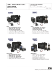
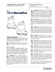
Ion Endeavor® Pump Controller
Digital Level Control with Pump Alternation
and High Water Alarm
OPERATION MANUAL
Dated: 05/19/2014
Document Name: IonEndeavor_OM
Page 1 of 8
General Overview
The Ion® Endeavor is a pump controller that senses
a water level of up to 72", has a configurable water
level/pump turn-on setting, the ability to run two
pumps simultaneously, pump alternation, pump
failure sensing, local audible/visual alarm notification,
local alarm silencing, and remote alarm notification.
An optional Ethernet module provides a web page
interface that displays all system information and
alarm notification via email and text message.
Indicators
The front panel has LEDs, a display, and an audible
alarm to offer direct feedback to the user.
Note: This product is intended to be installed by
experienced professionals only.
Note: This product is required to plug into its own
dedicated circuit, rated at the controller’s required
voltage and amperage.
Note: This product is for use with manual pumps only.
A manual pump is a pump that runs when plugged into
an outlet, regardless of the presence of water. Water
sensor(s) are supplied with this unit for pump control.
Safety Precautions
WARNING: To prevent fire or shock hazard,
do not expose this product to rain or moisture.
This product has a NEMA-1 rated enclosure for use in
an indoor environment. Never spill liquid of any kind
on the product.
DANGER: Risk of electric shock. To reduce
risk of electric shock, do not remove cover.
There are no user-serviceable parts inside. Refer
servicing to qualified service personnel.
DANGER: To prevent electric shock, ensure
product is connected to a grounded outlet.
The electrical outlet should be properly wired to a
dedicated circuit breaker. Proper short-circuit and
overload protection must be provided at the
distribution panel. Install in accordance with all local
and national electrical codes. Recommended
mounting is above floor level. For best performance,
do not use electrical extension cords.
Buttons
The front of the controller has buttons labeled
“SILENCE”, “RESET” and “PUMP TURN ON LEVEL”.
The SILENCE button mutes the audible alarm when
an alarm is active. Any future alarms will activate the
audible alarm again.
The RESET button restarts the controller as if it were
unplugged. At start up, the controller runs pump #1
temporarily, followed by the second pump, if it exists
(as configured in the menu section).
The PUMP TURN ON LEVEL buttons set the water
level at which the first pump turns on. It is measured
in inches, up from the middle of the lower water
sensor (see the Installation section). When the water
level is pumped down to the middle of the lower water
sensor, the pump is turned off. This setting only
pertains to the lower water sensor.
Installation
NOTE: IF YOU ARE INSTALLING THE ENDEAVOR
TO AN EXISTING SUMPRO MODEL 75, PLEASE
CONTACT MANUFACTURER FIRST.
1. See Figure 1, Page 2. Clamp the two water
sensors to any riser pipes in the basin, one
water sensor above the other, with one near
the bottom of the pit and one at the very top.
If only one sensor is supplied, mount it near
the bottom of the pit. The bottom water sensor
must be mounted above all pump intakes and
will be used for day-to-day operation; the top
Register your product at www.ionproducts.net
Ion Endeavor® Pump Controller
Digital Level Control with Pump Alternation
and High Water Alarm
one, if supplied, will be used as a backup for
high water level sensing. Again, note that when
the water is pumped down to the middle of the
lower water sensor, any running pump will turn
off. If the water rises to the middle of the top
Figure 1
HIGH
WATER
ALARM
LEVEL
HIGH
WATER
SENSOR
DIGITAL
LEVEL
SENSOR
Dated: 05/19/2014
Document Name: IonEndeavor_OM
Page 2 of 8
the controller’s operating mode in the Menu
section.)
Setup
Plug the controller into the electrical outlet on the wall.
After it boots up, use the PUMP TURN ON LEVEL
buttons to set the desired water level (Setpoint)
at which the first pump should turn on. This level
is measured in inches, up from the middle of the
DIGITAL LEVEL SENSOR. This setting must be
below the bottom of the HIGH WATER SENSOR.
When the water level is pumped down to the middle
of the DIGITAL LEVEL SENSOR, any running pump
is turned off.
Note: This setting only pertains to the DIGITAL
LEVEL SENSOR, and will be retained in memory in
the event of a complete power failure.
Menu
PUMP
OFF
LEVEL
PRIMARY
PUMP
OPERATION MANUAL
OPTIONAL
2ND PUMP
water sensor, the controller will cue audible,
visual, and any remote alarms indicating a high
water level.
2. Mount the controller box to the wall in a place
where its cord can reach a dedicated electrical
outlet, and where the water sensors’ and
pumps’ cords can reach the controller box.
3. Connect the water sensors to the controller
box, ensuring that each sensor plugs into its
correct connector; the lower sensor in the pit
plugs into the DIGITAL LEVEL SENSOR jack
and the higher sensor (if supplied) plugs into
the HIGH WATER SENSOR jack.
(If only one sensor is supplied, disable the
High Water Sensor as described in the Menu
section.)
4. Plug the first pump into the outlet marked #1 on
the controller box. If there is a second pump,
plug it into the outlet #2 on the controller box.
(If only one pump is installed, properly set
Register your product at www.ionproducts.net
WARNING:
Changing
these
settings
incorrectly may adversely affect pumping
operation. If unsure about the settings, contact
technical support.
The controller has a menu of user-configurable
settings that may be altered if an unusual pump
installation requires it; normally, these settings do not
need to be changed. To enter this mode, press and
hold the PUMP TURN ON LEVEL up button and PUMP
TURN ON LEVEL down button together and then
press the RESET button, then follow the instructions
on the display. Note that once in the menu, pressing
RESET button discards any changes. The individual
settings are described below and, once saved, will be
retained in the event of a complete power failure.
Controller’s Operating Mode
The Controller’s Operating Mode can be set to one
of three modes. “Duplex Alternating” means the
controller will run one or two pumps together as
required. “Simplex Non-alternating” means there is
only one pump installed and it is plugged into pump
outlet #1. This allows a pump to be installed that
uses the entire current available to the controller by
the electrical outlet on the wall. “Simplex Alternating”
means there are two pumps installed, but they will
Ion Endeavor® Pump Controller
Digital Level Control with Pump Alternation
and High Water Alarm
never run simultaneously. This, too, allows each
pump to use the entire current available to the
controller by the electrical outlet on the wall since
the pumps will never be run together. The default is
Duplex Alternating mode.
Lag Start Level
The Lag Start Level is the number of inches above
the Setpoint that was configured in the Setup section
where the second pump will turn on. The default is 4
inches.
Excess Run Time
The Excess Run Time is the number of minutes
that a pump can run continuously before an alarm
is initiated. This alarm feature can be turned off by
setting it to zero. The default is 5 minutes.
Emergency Run Time
The Emergency Run Time is the minimum number of
seconds a pump(s) will run when water has reached
the HIGH LEVEL SENSOR. The default is 10 seconds.
High Water Sensor Enable
The High Water Sensor Enable tells the controller
whether to use water level readings from the HIGH
LEVEL SENSOR. The default is enabled.
Optional Alarm Module Enable
The Optional Alarm Module Enable tells the controller
whether an optional alarm module has been installed
inside the Endeavor. Such a module allows the
Endeavor to communicate its alarms in different
ways, such as via email. (If a module was just
installed and enabled, and still does not work, check
with technical support to ensure the Endeavor has the
correct version of software in it [the version number
is displayed after the RESET button is pushed].) The
default is Disabled.
Operation
The controller will turn one pump on whenever
the water level rises above the Setpoint that was
configured in the Setup section. If the water continues
to rise a few inches above that height (as configured
in the Menu), a second pump will be turned on, if it is
OPERATION MANUAL
Dated: 05/19/2014
Document Name: IonEndeavor_OM
Page 3 of 8
present and the controller is set to run in duplex mode
(see the Menu section). Any running pump will be
turned off after the water level is pumped down to the
middle of the DIGITAL LEVEL SENSOR.
Note: The controller will operate based on what
it is set to as described in the Menu section, under
“Controller’s Operating Mode”.
Under any of the following conditions, the controller
will enter a state of alarm:
• A pump failure has been detected.
• The water level reaches the HIGH LEVEL
SENSOR.
• A water level sensor has failed.
• A pump has been continuously running but the
water level remains above the DIGITAL LEVEL
SENSOR for an extended period of time (as
determined by the Menu setting).
Once in an alarm state, the controller will notify the
user that there may be trouble by:
• Initiating audible and visual cues.
• Breaking (electrically opening) the remote
alarm contacts which can be connected to
another alarming device, allowing it to inform
the user remotely (these contacts are normally
closed).
• Communicating the alarm to an optimal internal
alarm module for further handling.
Pump Fault Description
The controller determines pump condition via its
built-in electrical current sensor. Whenever a pump
draws abnormal current, the controller enters a state
of alarm telling the user that pump service is needed.
The following charts (See Figures 2, 3 and 4, Page
4) describe these conditions. An “X” means behavior
occurs for this pump state.
Register your product at www.ionproducts.net
Ion Endeavor® Pump Controller
OPERATION MANUAL
Dated: 05/19/2014
Document Name: IonEndeavor_OM
Digital Level Control with Pump Alternation
and High Water Alarm
Page 4 of 8
Figure 2: Duplex Operation – 2 pumps installed; both intended to run simultaneously when required.
Number
of Pumps
Running
2
Current
Open
Duplex
Duplex
Pump
Alternate
Remote
LCD
Pumping Pumping
To Next Beep
Alarm
Updates
Locked
Forced Locked
Pump
Bad‡
Contacts
Out*
Off†
Out*
Extreme
X
X
X
X
X
High, 3 Times
X
X
X
X
X
High
X
X
X
X
X
X
X
X
X
X
X
X
X
X
X
X
Low
1
Critical
N/A
N/A
Extreme, 3 Times
N/A
N/A
Extreme
N/A
N/A
X
X
X
High, 3 Times
N/A
N/A
X
X
High
N/A
N/A
X
X
Low
N/A
N/A
X
X
X
X
Figure 3: Alternating, Simplex Operation – 2 pumps installed, only one pump intended to run at one time.
Number
of Pumps
Running
1
Current
Pump
Locked
Out*
Bad
Alternate
To Next
Pump
‡
Beep
Open
Remote
Alarm
Contacts
LCD
Updates
Extreme
X
X
X
X
X
High, 3 Times
X
X
X
X
X
X
X
X
X
X
X
X
X
High
X
Low
Figure 4: Non-Alternating, Simplex Operation – 1 pump installed, only pump 1 will run. Pump 2 is disabled.
Number
of Pumps
Running
1
Current
Pump
Locked Out*
Bad‡
Beep
Open Remote
Alarm Contacts
LCD
Updates
Extreme
X
X
X
X
High, 3 Times
X
X
X
X
X
X
X
X
X
X
High
Low
X
*
Duplex Pump Mode or pump is permanently locked out from running until controller is reset.
†
Running two pumps simultaneously is temporarily disabled; that is, one pump is turned off.
‡
Pump is only run as a lag (secondary) pump.
Register your product at www.ionproducts.net
Ion Endeavor® Pump Controller
Digital Level Control with Pump Alternation
and High Water Alarm
Specifications
OPERATION MANUAL
Dated: 05/19/2014
Document Name: IonEndeavor_OM
Page 5 of 8
Troubleshooting
Remote Alarm
Contacts:
Normally Closed,
30 VAC/DC @ 1 A
Temperature
Range:
-20 °C to 60 °C (-4 °F to 140 °F)
Audible Alarm: > 90 dB at 2 feet
Enclosure:
NEMA-1 Polycarbonate
Dimensions
(controller):
8” x 6” x 4”
Dimensions
(sensors):
4.62” x 4.62”,
mounting straps: 5.25” x 3.50”
Adjustable
Mounting
Pattern:
8.75” x 4.25” or 6.75” x 6.25”
Mounting:
Up to #10 screws
Pump won’t turn on before reaching the HIGH
WATER SENSOR.
Setpoint is set too high.
The controller keeps reporting a water sensor
failure when there is only one sensor installed.
Make sure the HIGH WATER SENSOR is disabled
using the Menu as described above.
The controller keeps reporting a water sensor
failure.
Make sure each is plugged into its correct jack in the
controller box (see Installation section). Swapping
plugs may isolate the failed sensor.
Pump won’t turn off even though pit is empty.
Maximum Output
Model 200-AU
200-240 VAC @ 8A
Model 200-15
200-240 VAC @ 12 A
Model 100-15
120 VAC @ 12 A
Model 100-20
120 VAC @ 16 A
The lower sensor (“DIGITAL LEVEL SENSOR”)
must be mounted above all pump intakes.
The newly added optional alarm module doesn’t
work.
Enable the optional alarm module using the Menu
settings (see Menu section). If still inoperative,
contact technical support to determine whether the
Endeavor has the software version (shown after
pressing RESET) that supports the new module.
Register your product at www.ionproducts.net
Ion Endeavor® Pump Controller
Digital Level Control with Pump Alternation
and High Water Alarm
noteS
Register your product at www.ionproducts.net
OPERATION MANUAL
Dated: 05/19/2014
Document Name: IonEndeavor_OM
Page 6 of 8
Ion Endeavor® Pump Controller
Digital Level Control with Pump Alternation
and High Water Alarm
OPERATION MANUAL
Dated: 05/19/2014
Document Name: IonEndeavor_OM
Page 7 of 8
3 Year Residential Warranty
1.
Coverage and Term. Metropolitan Industries, Inc. (“Metropolitan”) warrants to the original
purchaser (the “Buyer”) of each Ion® product (the “product”), that any part thereof which proves to be
defective in material or workmanship within three (3) years from date of manufacture, will be replaced at no
charge with a new or remanufactured part, F.O.B. factory. Buyer shall be responsible for all freight charges
and all costs of field labor or other charges incurred in the removal and/or reinstallation of any product, part
or component thereof.
2.
Exclusions. THE WARRANTY IS SUBJECT TO THE FOLLOWING CONDITIONS AND
EXCLUSIONS:
(a)
The Warranty excludes products or workmanship which becomes defective as a result
of: (i) earthquake, fire, storms, the elements or any other acts of God; (ii) normal wear and tear from use;
(iii) accident, misuse, abuse or neglect; (iv) modifications made by Buyer or any third party, other than
Metropolitan; and (v) Buyer’s failure to properly install, maintain, service and/or operate the product under
normal conditions and according to manufacturer’s instructions.
(b)
Metropolitan shall not be responsible for, and the Warranty shall not cover, extended
damage which occurs because of Buyer’s failure to notify Metropolitan promptly in writing of apparent
defects.
(c)
Any part or component designated as manufactured by anyone other than Metropolitan
shall be covered only by the express warranty of the manufacturer thereof.
(d)
The Warranty shall lapse upon Buyer’s failure to fully comply with the terms and conditions
of its contract with Metropolitan, including Buyer’s failure to pay the purchase price for the product or any
portion thereof. Buyer’s subsequent compliance with the terms and conditions of any such contract, will not
cause the term of the Warranty to extend beyond the time period set forth above.
(e)
No actions taken by Metropolitan to correct a defect in a product shall extend the Warranty
beyond the period set forth above. Metropolitan shall not be obligated to remedy any defect, where otherwise
required pursuant to the Warranty unless and until Buyer notifies Metropolitan in writing of the defect and
then only if such notification is made prior to the expiration of the period set forth above.
3.
Process of Claims and Repairs. Metropolitan agrees that if the product or any part or component
thereof shall fail to conform to the terms of this Warranty, Metropolitan shall replace such nonconforming
product, part or component at the original point of delivery and furnish instruction for its disposition. Any
transportation charges involved in such disposition and all costs of field labor or other charges incurred in the
removal and/or reinstallation of any product, part or component thereof shall be the responsibility of Buyer.
4.
Limitation on Liability. Notwithstanding any provision to the contrary, Metropolitan’s entire
liability under this Warranty shall not in the aggregate exceed, and Buyer’s exclusive and sole remedies
are, to the extent permitted by law, shall be to secure replacement of the defective product. UNDER NO
CIRCUMSTANCES SHALL METROPOLITAN BE LIABLE UNDER THE WARRANTY FOR
ANY INDIRECT, PUNITIVE, SPECIAL, EXEMPLARY, CONSEQUENTIAL OR INCIDENTAL
DAMAGES (INCLUDING LOST PROFITS, REVENUE, USE OR ECONOMIC ADVANTAGE).
5.
Express Waiver of Any Other Warranties. THE EXPRESS WARRANTY SET FORTH IN THIS
WRITTEN WARRANTY IS THE ONLY WARRANTY MADE BY METROPOLITAN, OR ANY OTHER
PARTY, IN CONNECTION WITH ANY PRODUCT PURCHASED FROM METROPOLITAN.
NEITHER METROPOLITAN, NOR ANY OTHER PARTY, MAKES ANY OTHER EXPRESS OR
IMPLIED WARRANTY WHICH IS NOT SET FORTH HEREIN, AND METROPOLITAN HEREBY
DISCLAIMS AND BUYER HEREBY WAIVES ALL IMPLIED WARRANTIES, INCLUDING THE
IMPLIED WARRANTY OF MERCHANTABILITY AND THE IMPLIED WARRANTY OF FITNESS
FOR A PARTICULAR PURPOSE.
6.
Not Transferable. The Warranty may not be transferred and shall be void on the sale or other transfer
of the product.
7.
Products and Warranty Subject to Change. Metropolitan reserves the right to make revisions to its
products and their specifications, and to revise this Warranty and related information without notice.
Register your product at www.ionproducts.net