1
Ion Genesis® Pump Controller
OPERATION MANUAL
Dated: 10/06/2015
Document Name: IonGenesis_OM
Digital Level Control with Pump Alternation
and High Water Alarm
Page 1 of 8
®
Indicators
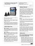
The front panel has lights, a display, and a sounder to
offer direct feedback to the homeowner.
®
Buttons
The front of the controller has buttons labeled “RESET/
TEST” and “PUMP TURN ON LEVEL”.
®
The RESET/TEST button has two functions and may
be depressed at any time.
1. This can be used for pump troubleshooting.
Marks & Meanings
DANGER: This sign warns that the failure to
follow the directions given could cause
serious risk to individuals or objects.
WARNING: This sign warns the operator that
the failure to follow an instruction may damage
the pump and/or the system.
Introduction
Thank you for purchasing an Ion Genesis® controller.
Take the time to read the instructions carefully before
using this appliance. We strongly recommend that
you keep this instruction manual in a safe place for
future reference.
The Ion Genesis® is a residential sump pump
controller for 1 or 2 pumps that includes redundant
water level sensors, a configurable water level/pump
turn-on setting, 2-pump alternation, pump failure
sensing, local audible/visual alarm notification, and
optional remote alarm notification. The Ion Genesis®
is capable of running only one pump at a time.
WARNING: This product is for use with
manual pumps only. A manual pump is a
pump that runs when plugged into an outlet. Sensors
are supplied with this unit for control.
WARNING: This pump controller is for use in
one sump pit only.
2. The controller will remember how many pumps
are available for future use. When pushed, it
runs the first pump temporarily, followed by
the second pump if it exists. This button must
be pushed once after removing or adding any
pumps.
The PUMP TURN ON LEVEL buttons set the water
level at which a pump turns on. This level is measured
in inches, up from the middle of the lower water
sensor (see the Installation section). When the water
level is pumped down to the middle of the lower water
sensor, the running pump is turned off. This setting
only pertains to the lower water level sensor.
Safety Precautions
WARNING: To prevent fire or shock hazard,
do not expose this product to rain or moisture.
This product has a NEMA-1 rated enclosure for use in
an indoor environment. Never spill liquid of any kind
on the product.
DANGER: Risk of electric shock. To reduce
risk of electric shock, do not remove cover.
There are no user-serviceable parts inside. Refer
servicing to qualified service personnel.
DANGER: To prevent electric shock, ensure
product is connected to a grounded outlet. The
electrical outlet should be properly wired to a dedicated
15 amp circuit breaker. Proper short-circuit and
overload protection must be provided at the distribution
panel. Install in accordance with all local and national
electrical codes. Recommended mounting is above
floor level. For best performance, do not use electrical
extension cords.
www.ionproducts.net
Ion Genesis® Pump Controller
Digital Level Control with Pump Alternation
and High Water Alarm
Installation
OPERATION MANUAL
Dated: 10/06/2015
Document Name: IonGenesis_OM
Page 2 of 8
Figure 1
WARNING: The water level sensors have
integrated vent tubes in their cords. Never
expose the plug ends of the cords to water, dirt, or
moisture. Be especially careful during installation.
1. See Figure 1, page 2. Clamp the two water
sensors to any head pipe in the pit, one water
sensor above the other with one near the
bottom of the pit and one at the very top. The
bottom water sensor must be mounted above
all pump intakes and will be used for day-to-day
operation; the top one will be used as a backup
for high water level sensing. Again, note that
when the water is pumped down to the middle
of the lower water sensor, the running pump will
turn off. If the water rises to the middle of the
top water sensor, the controller will cue audible,
visual, and any remote alarms.
2. Mount the controller box to the wall in a place
where its cord can reach a dedicated 120 volt
AC electrical outlet (rated for at least 15 amps),
and where the water sensors’ and pumps’ cords
can reach the controller box.
HIGH
WATER
ALARM
LEVEL
DIGITAL
LEVEL
SENSOR
PUMP
OFF
LEVEL
PRIMARY
PUMP
OPTIONAL
2ND PUMP
Figure 2
3. See Figure 2, page 2. Connect the water
sensors to the controller box, ensuring that
each sensor plugs into its correct connector.
The lower sensor plugs into the jack labeled
“DIGITAL LEVEL SENSOR” and the higher
sensor plugs into the jack labeled “HIGH
WATER SENSOR”. Securely fasten the cables
in a manner to relieve unnecessary force on the
connectors.
4. Plug a pump into the outlet marked “PUMP 1”
on the controller box. If there is a second pump,
plug it into the outlet “PUMP 2” on the controller
box.
HIGH
WATER
SENSOR
Bottom of Controller Box
DIGITAL
LEVEL
SENSOR
REMOTE
ALARM
CONTACT
5. If connecting a home alarm system to the Ion
Genesis®, make the connection to the 6P6C
jack labeled “REMOTE ALARM CONTACT”.
The center most pins (# 3 and 4) are used for
this circuit, and are normally closed (N/C) under
normal conditions. These pins electrically open
in an alarm condition (see Alarms section).
www.ionproducts.net
HIGH
WATER
SENSOR
Ion Genesis® Pump Controller
Digital Level Control with Pump Alternation
and High Water Alarm
Setup
OPERATION MANUAL
Dated: 10/06/2015
Document Name: IonGenesis_OM
Page 3 of 8
WARNING: This setting must be set below
the bottom of the HIGH WATER SENSOR.
Plug the Ion Genesis® into the electrical outlet. The
controller will automatically sense the connected
pumps at this time by running each briefly. If they do
not run, push the RESET/TEST button to ensure the
controller “counts” each pump plugged into it. (Each
pump must run temporarily for it to be counted.) If
they still do not run, or the controller states they are
absent (unplugged), call for service.
Note: This setting only pertains to the lower water
level sensor, and will be retained in memory in the
event of a complete power failure.
Using the PUMP TURN ON LEVEL buttons, set the
desired water level (Setpoint) at which a pump should
turn on. This level is measured in inches, up from the
middle of the lower water sensor (DIGITAL LEVEL
SENSOR, see Figure 1, page 2).
It is recommended that the system be tested by filling
the pit with water using a hose. The first pump should
turn on and empty the pit of water. If a second pump is
installed, filling the pit again should cause the second
pump to run.
Typical Installation
ION GENESIS®
CONTROLLER
The water level within the pit is monitored and
displayed as “Level”. When the water level is pumped
down to the middle of the lower water sensor, the
pump is turned off.
To test the alarm functions, simply apply gentle
pressure with a finger to the underside of the top level
sensor (HIGH WATER SENSOR). The controller
should cue audible and visual alerts, and engage any
alarm dialers and/or external devices that may be
connected for remote notification.
Operation
General
WATER LEVEL
SENSORS
The Ion Genesis® controller continuously monitors
the pit’s water level (“Level” on the display) and will
turn the pump on whenever the Level rises above
the turn-on height (“Setpoint”) configured during
setup. The pump will be turned off after the water is
pumped down to the middle of the lower water sensor
(DIGITAL LEVEL SENSOR). If there is a second
pump installed, it will be put in sequence and run the
next time a pump is called for. This alternation keeps
wear even between the pumps over time. Additionally,
if one pump experiences a problem, the controller will
automatically try the alternate pump.
NOTE: The controller only runs one pump at a time.
PUMPS
Figure 3
www.ionproducts.net
Ion Genesis® Pump Controller
Digital Level Control with Pump Alternation
and High Water Alarm
Alarms
Under any of the following conditions, the controller
will enter a state of alarm:
OPERATION MANUAL
Dated: 10/06/2015
Document Name: IonGenesis_OM
Page 4 of 8
Specifications
Voltage:
120 VAC, 60 Hz
•
A pump has been continuously running for five
minutes.
Output Capacity
(per outlet):
•
A pump has been called but is not evacuating the
pit.
15 A (max)
12 FLA, 72 LRA
1/2 HP
Remote Alarm
Contacts:
•
An abnormal pump current has been detected.
Normally closed (open
during alarm state) 30
VAC/DC @ 1 A MAX
•
A level sensor fault has been detected.
Temperature Range:
0 °C to 40 °C
(32 °F to 104 °F)
•
The pit water level reaches the HIGH WATER
SENSOR.
Audible Alarm:
80 dB at 10 ft.
Enclosure:
NEMA-1 UL94V-0 ABS
Mounting Hardware
(Controller):
(4) #10 screws
Mounting Dimensions
(Controller):
8.25” x 3.50”
Once in an alarm state, the controller will notify the
homeowner that there may be trouble by initiating
audible and visual cues, and by opening the alarm
contacts.
Remote Alarm
The Ion Genesis® controller will break (electrically
open) the REMOTE ALARM CONTACT during an
alarm state or power failure. This contact may be
connected to another device installed in the home, a
home monitoring service, or an optional phone dialer.
Accessories
Ion® StormPro® 35AC
Battery backup for AC
pumps rated to 5.5 amps.
See Installation Step 5 for more information pertaining
to the REMOTE ALARM CONTACT.
SUMPRO® 100
Battery backup for AC pumps
rated to 12 amps.
Phone Dialer
Can be programmed with up to
nine phone numbers to call in case
of high water or other alarm.
For operation or installation instructions for these
accessories, call 800 323-1665.
www.ionproducts.net
Ion Genesis® Pump Controller
Digital Level Control with Pump Alternation
and High Water Alarm
OPERATION MANUAL
Dated: 10/06/2015
Document Name: IonGenesis_OM
Page 5 of 8
Troubleshooting
Symptom
Cause
Measures
Power light not illuminated and
display is blank.
Tripped breaker.
Reset breaker.
Faulty outlet.
Check outlet/wiring.
Pump(s) run but will not pump
down water.
Restricted pump or pipe.
Clear pump or pipe.
Failing pump.
Compare water output to similar pump.
Bad check valve.
Check for proper operation of check valve.
High incoming water flow.
Pump(s) undersized for incoming water flow, replace
with higher capacity pump(s).
Pit empty but pump won’t shut
off.
The DIGITAL LEVEL SENSOR is mounted too
low in the pit.
The lower sensor (DIGITAL LEVEL SENSOR) must
be mounted above all pump intakes. Remount sensor
higher.
Remote contact not working.
Faulty wiring.
Use ohmmeter to test continuity of terminals. You
should see continuity in normal operation, activate
high water alarm - you should measure an open.
Consult a qualified electrician for all wiring problems.
Display shows “5 Minute Pump
Run Fault”.
A pump has been constantly running for longer
than 5 minutes. Pump(s) is at least temporarily
undersized for incoming water flow, the head
pipe is restricted, or a pump is failing.
Watch pit’s water level closely, check for any
restrictions, or replace pump(s) ensuring that the new
pump has proper flow capacity for incoming water
flow.
Display shows “Pump Faulted”.
A pump’s electrical current draw is higher or
lower than expected.
Replace the faulty pump, plug pump into outlet, or
press RESET/TEST to reinitialize controller.
Display shows
“Sensor Faulted”.
One of the water level sensors is unplugged or
faulted.
Unplug then reconnect both water level sensors. If
condition persists, replace the failing sensor.
Display shows “High Water
Level”.
The water level in the pit has reached the HIGH
WATER SENSOR. Either a pump(s) is at least
temporarily undersized for incoming water flow,
the head pipe is restricted, or a pump is failing
or has failed.
Make sure a pump is running. If not, press the
RESET/TEST button, and check again. If still not
running, call for service. Otherwise check for any
restrictions, or replace pump(s) ensuring that the new
pump has proper flow capacity for incoming water
flow.
The PUMP TURN ON LEVEL setting is set too
high.
The PUMP TURN ON LEVEL setting needs to be
set below the height of the HIGH WATER SENSOR.
Follow the instructions in the Setup section.
www.ionproducts.net
Ion Genesis® Pump Controller
OPERATION MANUAL
Dated: 10/06/2015
Document Name: IonGenesis_OM
Digital Level Control with Pump Alternation
and High Water Alarm
Ion Genesis®
and
Page 6 of 8
Dialer Installation
Phone Line
Ion Genesis®
Phone Dialer
(optional)
Pump 1
Power Cord
Pump 2
Remote
Alarm
Connection
High
Water
Sensor
Digital Level
Sensor
www.ionproducts.net
Ion Genesis® Pump Controller
Digital Level Control with Pump Alternation
and High Water Alarm
OPERATION MANUAL
Dated: 10/06/2015
Document Name: IonGenesis_OM
3 Year Residential Warranty
1.
Coverage and Term. Metropolitan Industries, Inc. (“Metropolitan”) warrants to the original
purchaser (the “Buyer”) of each StormPro/Sumpro product (the “product”), that any part thereof which proves
to be defective in material or workmanship within three (3) years from date of manufacture, will be replaced at
no charge with a new or remanufactured part, F.O.B. factory. Buyer shall be responsible for all freight charges
and all costs of field labor or other charges incurred in the removal and/or reinstallation of any product, part
or component thereof.
2.
Exclusions. THE WARRANTY IS SUBJECT TO THE FOLLOWING CONDITIONS AND
EXCLUSIONS:
(a)
The Warranty excludes products or workmanship which becomes defective as a result
of: (i) earthquake, fire, storms, the elements or any other acts of God; (ii) normal wear and tear from use;
(iii) accident, misuse, abuse or neglect; (iv) modifications made by Buyer or any third party, other than
Metropolitan; and (v) Buyer’s failure to properly install, maintain, service and/or operate the product under
normal conditions and according to manufacturer’s instructions.
(b)
Metropolitan shall not be responsible for, and the Warranty shall not cover, extended
damage which occurs because of Buyer’s failure to notify Metropolitan promptly in writing of apparent
defects.
(c)
Any part or component designated as manufactured by anyone other than Metropolitan
shall be covered only by the express warranty of the manufacturer thereof.
(d)
The Warranty shall lapse upon Buyer’s failure to fully comply with the terms and conditions
of its contract with Metropolitan, including Buyer’s failure to pay the purchase price for the product or any
portion thereof. Buyer’s subsequent compliance with the terms and conditions of any such contract, will not
cause the term of the Warranty to extend beyond the time period set forth above.
(e)
No actions taken by Metropolitan to correct a defect in a product shall extend the Warranty
beyond the period set forth above. Metropolitan shall not be obligated to remedy any defect, where otherwise
required pursuant to the Warranty unless and until Buyer notifies Metropolitan in writing of the defect and
then only if such notification is made prior to the expiration of the period set forth above.
3.
Process of Claims and Repairs. Metropolitan agrees that if the product or any part or component
thereof shall fail to conform to the terms of this Warranty, Metropolitan shall replace such nonconforming
product, part or component at the original point of delivery and furnish instruction for its disposition. Any
transportation charges involved in such disposition and all costs of field labor or other charges incurred in the
removal and/or reinstallation of any product, part or component thereof shall be the responsibility of Buyer.
4.
Limitation on Liability. Notwithstanding any provision to the contrary, Metropolitan’s entire
liability under this Warranty shall not in the aggregate exceed, and Buyer’s exclusive and sole remedies
are, to the extent permitted by law, shall be to secure replacement of the defective product. UNDER NO
CIRCUMSTANCES SHALL METROPOLITAN BE LIABLE UNDER THE WARRANTY FOR
ANY INDIRECT, PUNITIVE, SPECIAL, EXEMPLARY, CONSEQUENTIAL OR INCIDENTAL
DAMAGES (INCLUDING LOST PROFITS, REVENUE, USE OR ECONOMIC ADVANTAGE).
5.
Express Waiver of Any Other Warranties. THE EXPRESS WARRANTY SET FORTH IN THIS
WRITTEN WARRANTY IS THE ONLY WARRANTY MADE BY METROPOLITAN, OR ANY OTHER
PARTY, IN CONNECTION WITH ANY PRODUCT PURCHASED FROM METROPOLITAN.
NEITHER METROPOLITAN, NOR ANY OTHER PARTY, MAKES ANY OTHER EXPRESS OR
IMPLIED WARRANTY WHICH IS NOT SET FORTH HEREIN, AND METROPOLITAN HEREBY
DISCLAIMS AND BUYER HEREBY WAIVES ALL IMPLIED WARRANTIES, INCLUDING THE
IMPLIED WARRANTY OF MERCHANTABILITY AND THE IMPLIED WARRANTY OF FITNESS
FOR A PARTICULAR PURPOSE.
6.
Not Transferable. The Warranty may not be transferred and shall be void on the sale or other transfer
of the product.
7.
Products and Warranty Subject to Change. Metropolitan reserves the right to make revisions to its
products and their specifications, and to revise this Warranty and related information without notice.
www.ionproducts.net
Page 7 of 8