1
Operating Instructions
LCD Video Monitor
Model No.
BT-LH910G
Before operating this product, please read the instructions carefully and save this
manual for future use.
SS0311HM0 -PS D
Printed in Japan
ENGLISH
VQT3N15
Read this first !
indicates safety information.
Ŷ DO NOT REMOVE PANEL COVERS BY
UNSCREWING THEM.
No user serviceable parts inside.
Refer servicing to qualified service personnel.
WARNING:
To reduce the risk of fire, do not expose this
equipment to rain or moisture.
To reduce the risk of fire hazard, keep this
equipment away from all liquids. Use and
store only in locations which are not exposed
to the risk of dripping or splashing liquids, and
do not place any liquid containers on top of
the equipment.
WARNING:
Always keep the tilt stand mounting screws
and protection panel screws out of the reach of
infants and small children.
CAUTION:
Excessive sound pressure from earphons and
headphones can cause hearing loss.
CAUTION:
To reduce the risk of fire and annoying
interference, use the recommended
accessories only.
CAUTION:
In order to maintain adequate ventilation, do not
install or place this unit in a bookcase, built-in
cabinet or any other confined space.
To prevent risk of fire hazard due to
overheating, ensure that curtains and any other
materials do not obstruct the ventilation.
)&&127,&(86$
This device complies with part 15 of the FCC Rules. Operation is subject to the following two
conditions:
(1) This device may not cause harmful interference, and (2) this device must accept any
interference received, including interference that may cause undesired operation
CAUTION:
This equipment has been tested and found to comply with the limits for a class A digital device,
pursuant to Part 15 of the FCC Rules. These limits are designed to provide reasonable protection
against harmful interference when the equipment is operated in a commercial environment. This
equipment generates, uses, and can radiate radio frequency energy and, if not installed and used in
accordance with the instruction manual, may cause harmful interference to radio communications.
Operation of this equipment in a residential area is likely to cause harmful interference in which case
the user will be required to correct the interference at his own expense.
:DUQLQJ
To assure continued FCC emission limit compliance, the user must use only shielded interface cables
when connecting to external units. Also, any unauthorized changes or modifications to this equipment
could void the user’s authority to operate it.
1RWLFH86$RQO\
Disposal may be regulated in your community due to Environmental considerations. For disposal or
recycling information, please visit Panasonic website: http://www.panasonic.com/environmental or call
1-888-769-0149.
(((<|QHWPHOL÷LQH8\JXQGXU
(((&RPSOLHVZLWK'LUHFWLYHRI7XUNH\
A rechargeable battery that is recyclable powers the product you have purchased.
2
Read this first !FRQWLQXHG
EMC NOTICE FOR THE PURCHASER/USER OF THE APPARATUS
1. $SSOLFDEOHVWDQGDUGVDQGRSHUDWLQJHQYLURQPHQW
7KHDSSDUDWXVLVFRPSOLDQWZLWK
standards EN55103-1 and EN55103-2 2009, and
electromagnetic environments E1, E2, E3 and E4.
3UHUHTXLVLWHFRQGLWLRQVWRDFKLHYLQJFRPSOLDQFHZLWKWKHDERYHVWDQGDUGV
!3HULSKHUDOHTXLSPHQWWREHFRQQHFWHGWRWKHDSSDUDWXVDQGVSHFLDOFRQQHFWLQJFDEOHV
The purchaser/user is urged to use only equipment which has been recommended by us as
peripheral equipment to be connected to the apparatus.
The purchaser/user is urged to use only the connecting cables described below.
!)RUWKHFRQQHFWLQJFDEOHVXVHVKLHOGHGFDEOHVZKLFKVXLWWKHLQWHQGHGSXUSRVHRIWKHDSSDUDWXV
Video signal connecting cables
Use double shielded coaxial cables, which are designed for 75-ohm type high-frequency
applications, for SDI (Serial Digital Interface).
Coaxial cables, which are designed for 75-ohm type high-frequency applications, are recommended
for analog video signals.
Audio signal connecting cables
If your apparatus supports AES/EBU serial digital audio signals, use cables designed for AES/EBU.
Use shielded cables, which provide quality performance for high-frequency transmission applications,
for analog audio signals.
Other connecting cables (IEEE1394, USB)
Use shielded cables, which provide quality performance for high-frequency applications, as
connecting cables.
When connecting to the DVI signal terminal, use a cable with a ferrite core.
If your apparatus is supplied with ferrite core(s), they must be attached on cable(s) following
instructions in this manual.
3. Performance level
The performance level of the apparatus is equivalent to or better than the performance level required by
these standards.
However, the apparatus may be adversely affected by interference if it is being used in an EMC
environment, such as an area where strong electromagnetic fields are generated (by the presence
of signal transmission towers, cellular phones, etc.). In order to minimize the adverse effects of the
interference on the apparatus in cases like this, it is recommended that the following steps be taken with
the apparatus being affected and with its operating environment:
1. Place the apparatus at a distance from the source of the interference.
2. Change the direction of the apparatus.
3. Change the connection method used for the apparatus.
4. Connect the apparatus to another power outlet where the power is not shared by any other
appliances.
Pursuant to at the directive 2004/108/EC, article 9(2)
Panasonic Testing Centre
Panasonic Service Europe, a division of Panasonic Marketing Europe GmbH
Winsbergring 15, 22525 Hamburg, F.R. Germany
3
Read this first !FRQWLQXHG
IMPORTANT SAFETY INSTRUCTIONS
1) Read these instructions.
2) Keep these instructions.
3) Heed all warnings.
4) Follow all instructions.
5) Do not use this apparatus near water.
6) Clean only with dry cloth.
7) Do not block any ventilation openings. Install in accordance with the manufacturer’s instructions.
8) Do not install near any heat sources such as radiators, heat registers, stoves, or other apparatus
(including amplifiers) that produce heat.
9) Do not defeat the safety purpose of the polarized or grounding-type plug. A polarized plug has two blades
with one wider than the other. A grounding-type plug has two blades and a third grounding prong. The
wide blade or the third prong are provided for your safety. If the provided plug does not fit into your outlet,
consult an electrician for replacement of the obsolete outlet.
10) Protect the power cord from being walked on or pinched particularly at plugs, convenience receptacles,
and the point where they exit from the apparatus.
11) Only use attachments/accessories specified by the manufacturer.
12) Use only with the cart, stand, tripod, bracket, or table specified by the manufacturer,
or sold with the apparatus. When a cart is used, use caution when moving the cart/
apparatus combination to avoid injury from tip-over.
13) Unplug this apparatus during lightning storms or when unused for long periods of time.
14) Refer all servicing to qualified service personnel. Servicing is required when the
apparatus has been damaged in any way, such as power-supply cord or plug is damaged, liquid has
been spilled or objects have fallen into the apparatus, the apparatus has been exposed to rain or
moisture, does not operate normally, or has been dropped.
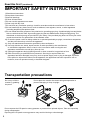
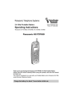
7UDQVSRUWDWLRQSUHFDXWLRQV
Do not try to lift the
monitor by grabbing
the panel.
Do not place the monitor face down during transportation to
prevent damaging it. Keep it upright.
Do not expose the LCD panel to strong pressure or pressure from pointed objects. Take care especially
during transportation.
Exposing the LCD panel to strong pressure may result in blurring or other damage.
4
Contents
Read this first ! .....................................................2
7UDQVSRUWDWLRQSUHFDXWLRQV .................................4
Standard accessories · 2SWLRQDOXQLWV ...............5
$ERXWWKLVLQVWUXFWLRQPDQXDO.............................5
3UHFDXWLRQVIRU8VH..............................................6
5HTXHVW .................................................................6
2XWOLQH ...................................................................7
6HOHFWLQJ$UHDRI8VH ...........................................8
Dimensions ...........................................................9
&RQWUROVDQG7KHLU)XQFWLRQV ...........................10
Front panel ........................................................10
Rear panel ........................................................13
6XSSO\LQJWKHSRZHU ..........................................14
Using an Anton/Bauer battery ...........................14
Using a V-mount type battery............................14
Using an external DC power supply..................15
9))XQFWLRQ .........................................................16
How to Remove the Tilt Stand ...........................17
2QVFUHHQ'LVSOD\ ..............................................18
Operating status display ...................................18
Picture and volume adjusting knobs status
display ...........................................................19
Sharpness display.............................................19
Function display ................................................19
Audio level meter display ..................................20
Time code (TC) display .....................................20
Closed caption (CC) display .............................21
DC power supply voltage and battery level
display ...........................................................21
+RZWR8VHWKH2Q6FUHHQ0HQX ......................22
Menu display .....................................................22
Menu operations ...............................................22
User Data .............................................................23
Saving user data ...............................................23
Loading user data .............................................23
0DLQ0HQX ...........................................................24
Menu configuration ...........................................24
2D/3D ASSIST ..................................................25
MARKER...........................................................25
Types of MARKER ............................................28
VIDEO CONFIG ................................................30
SYSTEM CONFIG ............................................34
Performing AUTO CALIBRATION .....................36
RESET operation ..............................................37
VF CONFIG ......................................................37
FUNCTION .......................................................38
GPI ....................................................................47
INPUT SELECT ................................................48
AUDIO...............................................................49
DISPLAY SETUP ..............................................50
CONTROL ........................................................51
HOURS METER ...............................................51
3D Assist Mode ...................................................52
MIRROR
(Left/Right and Top/Bottom inversion)...........54
SHIFT (Horizontal and Vertical Shift) ................54
COMPARISON (Composition Check) ...............54
CONVERGENCE (Convergence Check) ..........55
COLOR (Color Check) ......................................55
ZOOM FOCUS (Zoom and Focus Check) ........56
VERTICAL (Vertical Offset Check)....................57
OVERLAY (Parallax Check) ..............................58
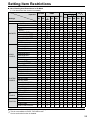
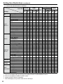
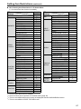
6HWWLQJ,WHP5HVWULFWLRQV ...................................59
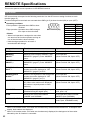
REMOTE Specifications .....................................62
GPI terminal ......................................................62
SERIAL terminal ...............................................64
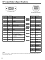
9)YLHZILQGHU6SHFLILFDWLRQV ..........................68
(UURUDQG:DUQLQJ'LVSOD\V ..............................69
Maintenance ........................................................69
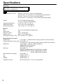
Specifications .....................................................70
6WDQGDUGDFFHVVRULHVÂ2SWLRQDOXQLWV
Ŷ Standard accessories
7LOW6WDQGî
7LOW6WDQG0RXQWLQJ6FUHZî &'520î
(The unit is shipped with the tilt stand already attached with the four screws.)
Ŷ 2SWLRQDOXQLWV
VF Cable BT-CS910G
$ERXWWKLVLQVWUXFWLRQPDQXDO
This instruction manual refers to BT-LH910G as “this unit.”
The illustrations, explanatory drawings, and other figures included in this instruction manual are for
illustrative purposes only and may differ from actual display.
HDMI, the HDMI logo, and High-Definition Multimedia Interface are trademarks or registered trademarks
of HDMI Licensing, LLC in the United States and/or other countries.
5
3UHFDXWLRQVIRU8VH
This product has been specially designed for commercial use. As such, it should be used and operated
only by persons with related expertise.
Ɣ The LCD screen is manufactured to precise
specifications. Although over 99.99 % of the
pixels function normally, 0.01 % of the pixels
are either missing or constantly lit (red, blue
or green). This is normal and not a cause for
concern.
Ɣ The protection panel and liquid crystal panel is a
specially manufactured component. Wiping it with
a hard cloth, or rubbing it vigorously will scratch
the surface.
Ɣ If a still image is displayed for an extended period
of time, it may generate a temporary afterimage
(phosphor burn-in). (However, such images can
be removed by displaying normal video for a
while.)
Ɣ The response speed and brightness of liquid
crystal vary with ambient temperatures.
Ɣ Do not install the unit in locations where enough
space cannot be provided around it as heat may
build up inside preventing normal operation. Be
sure to provide enough space around the unit.
Ɣ Exposing the LCD screen to intense light sources
will impair its characteristics and lower image
quality.
Ɣ In an environment exposed to drastic temperature
Ɣ Some video images may appear blurred on the
screen.
Ɣ Leaving the unit in a location exposed to high
temperature and humidity for an extended period
of time may damage the LCD screen and cause
blurring.
Ɣ Do not use the unit in excessively dusty
environments. Doing so may damage the LCD
screen.
Ɣ Using the unit in cases such as the following may
result in image and audio distortion due to the
influence of electromagnetic waves.
When in the vicinity of a TV or computer
When a mobile phone is on top of the unit
When near equipment that generates a power
magnetic field, such as a speaker or large
motor
Ɣ If the unit becomes unable to operate properly
due the influence of equipment that generates
magnetism, turn off the unit (if using a battery,
remove it) and then wait a while and then turn it
back on.
Ɣ Using the unit near radio broadcast equipment or
high-voltage equipment may result in image and
audio degradation.
fluctuations, condensation may build up on
and inside the LCD screen. This may lower the
quality of the screen and may damage it. If there
are drops of water on the case, turn off the power
and wait until the condensation has evaporated.
5HTXHVW
3OHDVHFRQILJXUHWKHIROORZLQJVHWWLQJEHIRUHXVLQJWKHXQLWIRUWKHILUVWWLPH
7KHXQLWLVVKLSSHGZLWKWKHDUHDRIXVHVHWWRWKHLQLWLDOVWDWH%HIRUHXVLQJWKHXQLWVHW
\RXUDUHDRIXVHDVGHVFULEHGLQ³6HOHFWLQJ$UHDRI8VH´RQSDJH
6
2XWOLQH
This unit is a liquid crystal display monitor for broadcasting and business use that is equipped with a 23 cm
(9.0 inch) (effective display area) liquid crystal display.
It can be used as a VF (viewfinder) for broadcasting and business cameras made by Panasonic.
Ŷ +LJK3HUIRUPDQFH/LTXLG&U\VWDO3DQHO
This product incorporates a WXGA (1280 x 768) class high-resolution IPS liquid crystal panel. It offers
excellent color reproduction, a wide viewing angle, and a fast response time.
Ŷ 6XSHUE0RYLQJ,PDJH4XDOLW\$FKLHYHGE\1HZ,PDJH3URFHVVLQJ(QJLQH
The 10-bit image processing engine facilitates accurate and smooth gradation results from low to high
brightness levels.
The incorporation of an I/P conversion circuit with a low delay of less than one field minimizes the delay
time between signal input and monitor display.
The incorporation of diagonal line compensation circuit reduces image degradation in the vertical
direction and jagged noise on diagonal lines.
The high-speed moving image response time provides vivid and clear image display.
Gamma compensation is performed for each monitor.
Ŷ ,QFOXGHV'$VVLVW)XQFWLRQV
Various assist functions are included to allow connecting the left and right connectors of a 3D camera to
the two SDI inputs and capturing 3D images that are easier to view on a 2D monitor. These functions also
make camera adjustments easier and reduce the preparation time required for 3D shooting.
Ŷ :LGH9DULHW\RI)XQFWLRQVDQG,QWHUIDFHV
Equipped with 3G-SDI, SDI (HD/SD compatible), HDMI, VIDEO, and YPBPR inputs.
FOCUS-IN-RED function (Displayed abbreviated to F-IN-R in the picture adjusting knob status display.)
Making camera focus adjustments is extremely easy because the section of the image in focus is
displayed in red to make it easy to understand what is in focus.
WFM (Y/R/G/B) and vectorscope display functions
Capable of input signal Y/R/G/B waveform display (when 3G-SDI, SDI, HDMI, VIDEO, or YPBPR input)
and vectorscope display.
Audio level meter display function and headphones jack
The level of audio signals embedded in 3G-SDI, SDI, and HDMI signals can be displayed. Furthermore,
support is also included for reference point setting, peak hold, and overrange display.
The incorporation of a headphones jack means you can check the audio. The channel can also be
selected in a menu.
Closed caption function
The captions added to video signals can be displayed during SDI and VIDEO input.
2-screen display function
The screen can be split into two to allow you to make a screen comparison for the same input
connectors and same format.
PIXEL TO PIXEL function
This function makes camera focus adjustment extremely easy because the input signals are displayed
without being resized.
When resizing is not performed, the 1080/60i signals can be expanded to the equivalent of an
approximately 13.5-inch wide monitor, and then checked.
Cross hatch display function
This function displays markers at regular vertical and horizontal intervals to facilitate easy composition.
7
6HOHFWLQJ$UHDRI8VH
The unit is shipped with the area of use set to the initial setting (NTSC) state. Before using the unit, select
the area of use. When you set the area of use, the factory default setting of the menu item on the right is
set to the value that matches the area of use. (For the procedure to restore the menu setting values to the
factory defaults, refer to “Loading user data” on page 23.)
AREA SETTING
NTSC
176&-
PAL
SMPTE-C
EBU
EBU
20 dB
20 dB
18 dB
0HQX,WHP
COLOR SPACE
HEAD ROOM
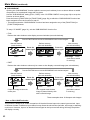
How to Select Area of Use
1. &RQQHFWWKHXQLWWRWKHSRZHUVXSSO\WXUQRQWKHSRZHUDQGSUHVVWKH>0(18@EXWWRQ
The MAIN MENU screen appears.
2. 3UHVV> @> @WRVHOHFW³6<67(0&21),*´DQGSUHVV>(17(5@
The “SYSTEM CONFIG” submenu screen appears.
3. 3UHVV> @> @WRVHOHFW³$5($6(77,1*´DQGSUHVV>(17(5@
The “AREA SETTING” value turns green.
4. 3UHVV> @> @WRVHOHFWWKHDUHDRIXVHIURP³176&176&-3$/´DQGSUHVV>(17(5@
The “YES/NO” confirmation screen appears.
5. 3UHVV> @> @WRVHOHFW³<(6´DQGSUHVV>(17(5@
The setting selected in step 4 is reflected in the factory defaults (FACTORY) or the current menu setting
values and the “SYSTEM CONFIG” submenu screen appears.
6. 3UHVV>0(18@WZLFHWRFORVHWKHPHQX
8
Dimensions
Unit: mm(inches)
204 (8-1/16)
3/8-16UNC
170 (6-11/16)
20.2
(13/16)
46
(1-13/16)
3/8-16UNC*1
78.5 (3-7/8)
65.5 (2-9/16)
230 (9-1/16)
195.7 (7-11/16)
11.5(7/16)
25.5 (1)
48.5
(1-15/16)
M3
17.55 (11/16)
183 (7-3/16)
118.2 (4-5/8)
98.5 (3-7/8)
214.5 (8-7/16)
M3
148.5 (5-7/8)
M3
M3
16
U
83/
C
N
20.2 (13/16)
U
16
*1
8-
N
3/
C
46
(1-13/16)
210 (8-1/4)
When the adapter is connected: 1/4-20UNC
9
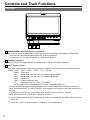
&RQWUROVDQG7KHLU)XQFWLRQV
Front panel
F-IN-R
PEAK/
PHASE
1
2
CHROMA
VOLUME/
BRIGHT
CONT./
B.LIGHT BT-LH910
3
1 +($'3+21(6RXWSXWMDFN0VWHUHRPLQLMDFN
Allows you to connect headphones to check the audio when inputting an SDI signal or HDMI signal.
* The volume and sound quality differ depending on the headphones.
In 3D assist mode, the audio of the SDI1 (L) side can be checked.
2 POWER switch/lamp
Switches the power supply ON/OFF. When the power is ON, the LED (green) lights up.
3
,13876(/(&7EXWWRQ
Selects the signal input line. Each time the button is pressed, the input changes in the following order:
9,'(2ĺ6',ĺ6',ĺ+'0,ĺ<3BPRĺ9)ĺ,176*
VIDEO : Video input
SDI1
: Serial digital interface input (compatible with 3G/HD/SD)
SDI2
: Serial digital interface input (compatible with HD/SD)
HDMI : HDMI input
YPBPR : Analog component input
VF
: Viewfinder input (VF-YPBPR / VF-VIDEO) *1
INT SG: Internal chart for adjustment [Color Bar + Grayscale] (page 74)
The input line when the power supply is switched ON is the one that was selected the last time the
power was switched OFF. The INPUT SELECT menu settings can be used to skip input lines that are
not used.
In 3D assist mode, the input is fixed to SDI1/SDI2 and the input line cannot be selected.
When the control lock is on, input lines cannot be selected.
It is not possible to switch to INT SG when two screens are displayed with the SUB WINDOW function
ĺSDJH
*1
10
The menu is used to set either YPBPR or VIDEO for the viewfinder input.
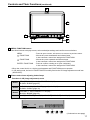
&RQWUROVDQG7KHLU)XQFWLRQVFRQWLQXHG
6
7
F-IN-R
4
PEAK/
PHASE
CHROMA
VOLUME/
BRIGHT
CONT./
B.LIGHT BT-LH910
5
8
4 0(18)81&7,21EXWWRQV
Use these buttons to display menus, select and adjust settings and confirm menu selections.
MENU
/ FUNCTION1
: Press to open a menu, exit a menu or return to a previous menu.
: Moves the cursor downwards and selects items.
It also confirms a menu item assigned to FUNCTION1.
: Moves the cursor upwards and selects items.
It also confirms a menu item assigned to FUNCTION2.
: Press to confirm a setting or to open a submenu.
It also confirms a menu item assigned to FUNCTION3.
/ FUNCTION2
ENTER / FUNCTION3
When the control lock is on, the key mark appears and FUNCTION does not operate.
In 3D assist mode, the item of FUNCTION3 is forcefully fixed to the 2D image adjustment mode item
(2D ADJUST).
5 3LFWXUHDQGYROXPHDGMXVWLQJNQREVODPSV
)XQFWLRQVLQ'LPDJHDGMXVWPHQWPRGH
Knob1
PEAK[PEAKING] 0 - 30 (0) / PHASE 0 - 60 (30)
R-GAIN / R-BIAS (page 32)
Knob2
CHROMA 0 - 60 (30) / F-IN-R (page 46) 0 - 30 (30)
G-GAIN / G-BIAS (page 32)
Knob3
VOLUME 0 - 60 (0) / BRIGHT 0 - 60 (30) /
B-GAIN / B-BIAS (page 32)
Knob4
CONT.[CONTRAST] 0 - 60 (50) / B.LIGHT[BACKLIGHT] 0 - 100 (80)
( ) denotes factory preset values.
[PHASE]
PEAK
20
EXIT
F-IN-R VOLUME CONT.
PHASE CHROMA BRIGHT B.LIGHT
F-IN-R
PEAK/
PHASE
CHROMA
VOLUME/
BRIGHT
CONT./
B.LIGHT
(Continued on next page)
11
&RQWUROVDQG7KHLU)XQFWLRQVFRQWLQXHG
)XQFWLRQVLQ'DVVLVWPRGH
Knob1
MIRROR (MIRROR) / HORIZONTAL (SHIFT) / MODE (CONVERGENCE) /
SIZE (COLOR) / ZOOM (ZOOM FOCUS) / EXPAND (VERTICAL) /
OVERLAY (OVERLAY)
Knob2
VERTICAL (SHIFT) / MANUAL (CONVERGENCE) /
FOCUS-IN-RED (ZOOM FOCUS) / MARKER1 (VERTICAL) / MARKER (OVERLAY)
Knob3
SPEED (CONVERGENCE) / MARKER2 (VERTICAL)
Knob4
ASSIST FUNCTION (All Functions)
( ): Selected assist function
These are rotary push knobs. You can press one of the four knobs to display the corresponding
assigned function and image adjusting knob status, and then make adjustments.
The setting value is saved and the indication disappears when you press [ENTER] or when 10
seconds elapses after the setting value is changed.
If you want to change the function assigned to a knob, press the knob and change the function. The
selected function is displayed in green.
When values are changed from the factory defaults, the LED above the knob (amber) lights.
Settings are loaded when the monitor is turned on. However, operating changes cannot be made in
the following conditions.
When the control lock is on, the key mark appears and setting values cannot be changed (page
51).
When the MONO function is ON (page 31), [PHASE] and [CHROMA] operations are disabled.
F-IN-R is enabled during operation of the FOCUS-IN-RED function.
While operating HV DELAY (page 41) (when set to any other setting than OFF), [BRIGHT]
operation is disabled.
The “CONTRAST” and “BACK LIGHT” operations are disabled in BLACK MODE.
* For the operating procedures of adjusting knobs in 3D assist mode, refer to “3D Assist Mode”
(page 52).
6 7DOO\/DPSV5HGDQG*UHHQ
Can be lit by a control signal (red tally and green tally) from a GPI/camera.
If the red tally and green tally light at the same time, the tally color will become amber.
7 Protection Panel
This panel is for protecting the liquid crystal.
The protection panel can be removed by removing the four screws. When attaching the panel, note
that there is no distinction between the back and front and the top and bottom.
8 Tilt Stand
The tilt stand allows you tilt the unit 15° forward or 20°
backward.
When tilting the unit, firmly hold the bottom of the stand
and move the top of the unit.
If you want to remove the tilt stand, refer to “How to
Remove the Tilt Stand” on page 17.
<Note>
When tilting the monitor, be careful not to trap a hand
between the monitor and stand.
12
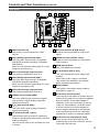
&RQWUROVDQG7KHLU)XQFWLRQVFRQWLQXHG
Rear panel
9
22
12
10 11
9
13
14
16
15
17
SERIAL
18
23
21
22
9 5($57$//<6UHG
Can be lit by a control signal from a GPI/
camera.
10 6',+'6'LQSXWWHUPLQDO%1&
This is the SDI1 input terminal. (Compatible
with HD/SD automatic switching, Compatible
with 3G-SDI)
When you use 3D assist mode (page 51), input
images for the left eye (L).
11 6',DFWLYHWKURXJKRXWSXWWHUPLQDO
This terminal outputs SDI1 input as is.
12 6',+'6'LQSXWWHUPLQDO%1&
This is the SDI2 input terminal. (Compatible
with HD/SD automatic switching)
When you use 3D assist mode (page 51), input
images for the right eye (R).
13 6',DFWLYHWKURXJKRXWSXWWHUPLQDO
This terminal outputs SDI2 input as is.
14 9,'(2<LQSXWWHUPLQDO%1&
This is the VIDEO signal (component signal)
input terminal/Y signal (analog component
signal) input terminal.
15 PB/PRLQSXWWHUPLQDO%1&
This is the PB/PR signal (analog component
signal) input terminal.
16 9)WHUPLQDO'68%SLQV
This terminal connects to the VF (viewfinder)
terminal of broadcasting and business cameras
made by Panasonic.
The unit can be used as the viewfinder for such
a camera.
20 19
23
17 *3,LQSXWWHUPLQDO'68%SLQV
External control is possible by using a GPI
signal.
18 6(5,$/WHUPLQDO'68%SLQV
External control is possible by using an RS232C interface.
19 +'0,LQSXWWHUPLQDO
This is the HDMI input terminal.
20 '&,1WHUPLQDO;/5SLQV
This is the external DC power supply input
terminal.
When a DC power supply is connected
concurrently with the battery, the external
power input takes precedence.
21 %DWWHU\KROGHU
This holder is used with a battery made by
Anton/Bauer. (page 14)
22 6FUHZKROHVIRUIL[LQJWULSRG
There are two screw holes on both the top and
bottom for fixing the unit to a tripod (compatible
with 3/8-16UNC). A removable adapter is
installed in one of the screw holes on the top
of the unit, and enables a 1/4-20UNC screw
to fit in the screw hole. Decide whether to
use the adapter depending on the diameter
of the tripod’s fixing screw. Use a flat-blade
screwdriver to remove or install the adapter.
23 6FUHZKROHVIRUPXOWLSXUSRVHIL[LQJ
There are four screw holes (M3) for multipurpose fixing on the rear of the unit, and two
on each the left and right.
13
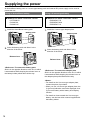
6XSSO\LQJWKHSRZHU
An Anton/Bauer battery pack or V-mount type battery pack and external DC power supply can be used to
power this unit.
8VLQJDQ$QWRQ%DXHUEDWWHU\
Ŷ Batteries for which connection verified
HYTRON 50
DIONIC 90
DIONIC HC
8VLQJD9PRXQWW\SHEDWWHU\
Ŷ Batteries for which connection verified
ENDURA E-7S
ENDURA E-HL9
ENDURA E-10
1. Install the Anton/Bauer battery pack.
1. Install the V-mount type adapter plate.
%DWWHU\SDFN
2. Insert the battery pack and slide it in the
direction of the arrow.
Adapter plate
2. Insert the battery pack and slide it in the
direction of the arrow.
Release lever
Release lever
5HIHUHQFH!7RUHPRYHWKHEDWWHU\SDFN
Slide it in the opposite direction to the one in which
it was attached while keeping the release lever on
the battery holder pulled down all the way.
<Reference> To remove the adapter plate
Slide it in the opposite direction to the one in which
it was attached while keeping the release lever on
the adapter plate pulled down all the way.
<Notes>
For details on the V-mount type adapter plate,
contact the place of purchase.
When you use a V-mount type adapter plate, the
% (percent) indication cannot be displayed even
if you use a battery with a battery level display
function.
For details on how to attach the V-mount type
battery, see the instruction manual supplied with
the battery holder.
14
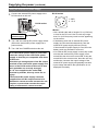
6XSSO\LQJWKHSRZHUFRQWLQXHG
8VLQJDQH[WHUQDO'&SRZHUVXSSO\
1. Connect the external DC power supply to the
'&,1VRFNHW
DC IN socket on this unit.
4
1
'&,1VRFNHW
External DC
SRZHUVXSSO\
2. Turn “ON” the external DC power supply switch.
(Where the external DC power supply has a
power switch)
3. Turn “ON” the POWER switch on this unit.
,IDQH[WHUQDO'&SRZHUVXSSO\LVXVHGWKHQ
FKHFNWKHUDWLQJVRIWKHH[WHUQDO'&SRZHU
VXSSO\VRWKDWWKH\DUHFRPSDWLEOHZLWKWKRVH
RIWKLVXQLW
&KHFNWKHSLQDUUDQJHPHQWVRIWKH'&RXWSXW
WHUPLQDORIWKHH[WHUQDO'&SRZHUVXSSO\DQG
WKRVHRIWKH'&,1VRFNHWRIWKLVXQLWVRWKDW
WKHLUSRODULWLHVDUHFRUUHFWO\DUUDQJHG
,I9DUHVXSSOLHGWRWKHXQLW¶V*1'
WHUPLQDOE\PLVWDNHWKLVPD\FDXVHILUHRU
LQMXU\
7KHH[WHUQDO'&SRZHUVXSSO\FDQQRWEH
VXSSOLHGIURPWKH'&RXWSXWWHUPLQDORID
3DQDVRQLFFDPHUDUHFRUGHUEHFDXVHWKHXQLW
UHTXLUHVDFXUUHQWWKDWH[FHHGVWKHRXWSXW
UDWLQJRID3DQDVRQLFFDPHUDUHFRUGHU
2
3
1: GND
4: +12 V
<Notes>
Use a shield cable with a length of 2 m (6.56 feet)
or less for the DC cord. Use of cords any longer
than 2 m (6.56 feet) may result in noise appearing
on the screen.
If the battery pack and an external DC power
supply are connected simultaneously, then the
external DC power supply will have priority.
If the external DC power supply is used, then the
battery pack may be fitted or removed.
If an external DC power supply is used, then make
sure that the external DC power supply is first
turned ON, then this unit is turned ON. If they are
turned ON in the reverse order, then this unit may
malfunction, because the output voltage of the
external DC power supply will gradually increase.
Input voltage that above the specification is not
displayed accurately.
15
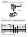
9))XQFWLRQ
The unit can be connected to broadcasting and business cameras made by Panasonic and used as a VF (viewfinder).
If you want to use the unit as a VF (viewfinder), remove the tilt stand (page 17).
VF cable (Option)
Part number: BT-CS910G
VF connector on unit side
Camera platform *1 (commercially available)
Camera side VF terminal
*1
Use a camera platform that can fully withstand the weight of the unit (1.7 kg (3.75 lb)).
<Note>
This unit requires a current that exceeds the output rating of a Panasonic camera-recorder, so the external
DC power cannot be supplied from the DC output terminal of a Panasonic camera-recorder.
Do not use the battery pack. If this unit is mounted on the camera-recorder with the battery pack attached,
the camera platform may be damaged. Use an external DC power supply.
Contact your vendor for details of broadcasting and business camera-recorders that will be launched in the
future.
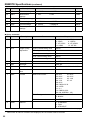
Ŷ 3DQDVRQLFFDPHUDUHFRUGHUVWKDWDOORZWKHXQLWWREHFRQQHFWHGDVD9)YLHZILQGHU
Panasonic Camerarecorder
VF Video
6LJQDOV*1
9)&RPPXQLFDWLRQ
Monitor
ĺ&DPHUD
TALLY
YPBPR VIDEO ZEBRA*3
AJ-HPX3100G
AJ-HPX3700G
AJ-HPX2700G
AJ-HPX2000/2100
AJ-HDX900
AG-HPX500/502
(Monochrome images
of SD resolution)
*1
*2
*3
*4
16
&DPHUDĺ0RQLWRU*2
RED*
GREEN
9
4
9
9
9
9
9
9
9
9
9
9
9
9
9
9
9
9
9
9
9
9
9
Indication of
Abnormal
2SHUDWLQJ6WDWH
&KDQJLQJRI
Aspect (SD
0RGH2QO\
9
9
9
9
9
9
9
9
9
Configure the menu settings in accordance with the output signal format of the camera (page 48).
For the settings, refer to the instruction manual of the camera.
The ZEBRA information can be set for the camera (page 37).
The tally lamp on the rear of the monitor lights in accordance with the REAR TALLY setting (page 37).
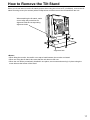
How to Remove the Tilt Stand
When you do not want to use the tilt stand such as when using the unit as a VF (viewfinder), remove the tilt
stand mounting screw (four screws) with a Phillips driver and then remove the tilt stand from the unit.
When attaching the tilt stand, make
sure to align the protrusions for
alignment with the corresponding
alignment holes.
Alignment hole
<Notes>
When tilting the monitor, be careful not to trap a hand between the monitor and stand.
When not using the tilt stand, take care that the unit does not fall over.
When the unit will be permanently installed in one place, we recommend securing it in place using the
screw holes at the bottom of the stand.
17
2QVFUHHQ'LVSOD\
The screen shows information such as the operating status display, picture adjusting knob status, sharpness
display, function display, audio level meter display, time code display, closed caption display, DC power
supply voltage and battery level display, and menu display.
2SHUDWLQJVWDWXVGLVSOD\
1
3
7
2
5 6
YPBPR 1080/60i
P-P FILM
DC14.0V
4
50%
8
7KHVHOHFWHGLQSXWOLQHSDJH
SDI1, SDI2, HDMI, VIDEO, YPBPR, VF-YPBPR/VF-VIDEO, INT SG.
6LJQDOIRUPDW
“UNSUPPORT SIGNAL” appears if an unsupported signal is input. It may also indicate that the format
selected in the “INPUT SELECT” menu does not match the input signal.
“NO SIGNAL” appears without input signal.
9DULRXVLQGLFDWLRQV3,;(/723,;(/PRGH
This indicates the PIXEL TO PIXEL mode is engaged.
9DULRXVLQGLFDWLRQV),/0PRGH
This indicates that “GAMMA SELECT” of the “VIDEO CONFIG” is set to “FILM.”
9DULRXVLQGLFDWLRQVZDUQLQJRILPSURSHURSHUDWLRQVWDWXVIRUWKHFDPHUDVHWWLQJV
This indicates there is an improper operation status relative to the camera settings.
The condition to display differs depending on the type and settings of the camera used in combination
with the unit. For details, see the instruction manual of the camera.
9DULRXVGLVSOD\VORFNVHWWLQJ
This indicates that the front operations lock is on. (page 51)
'&SRZHUVXSSO\YROWDJHGLVSOD\
DC power supply voltage is displayed.
%DWWHU\OHYHOGLVSOD\
When you are using an Anton/Bauer battery with a battery level display function, the battery level is
LQGLFDWHGE\WKHQXPEHURIŶDQGDSHUFHQWDJH:KHQ\RXDUHXVLQJDEDWWHU\RWKHUWKDQWKDWRUWKH$&
adapter, the display may not be shown or the battery level may not be indicated correctly. The battery
OHYHOLVLQGLFDWHGE\DQXPHULFDOYDOXHLQLQFUHPHQWV$OVRWKHUHDUHVHYHQŶVHJPHQWVWRLQGLFDWH
the battery level, and all seven of them are displayed until the battery level is approximately 70 %. After
WKDWWKHQXPEHURIŶLVUHGXFHGE\RQHIRUHDFKUHGXFWLRQLQEDWWHU\SRZHUDQGQRPDUNVDUH
displayed when the battery level falls below approximately 10 %.
The indication can be turned ON/OFF in “BATTERY REMAIN” of the “SYSTEM CONFIG” menu (page 34).
<Notes>
The display state of the status can be set in “STATUS DISPLAY” of the “SYSTEM CONFIG” menu (page 34).
“UNSUPPORT SIGNAL” and “NO SIGNAL” may not be properly displayed.
For details on the operation status display in 3D Assist mode, refer to “3D Assist Mode” (page 52).
18
2QVFUHHQ'LVSOD\FRQWLQXHG
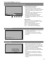
3LFWXUHDQGYROXPHDGMXVWLQJNQREVVWDWXVGLVSOD\
[PHASE]
20
PEAK
EXIT
F-IN-R VOLUME CONT.
PHASE CHROMA BRIGHT B.LIGHT
F-IN-R
PEAK/
PHASE
CHROMA
VOLUME/
BRIGHT
CONT./
B.LIGHT
3LFWXUHDGMXVWLQJNQRESDJH
These are rotary push knobs.
If you press a knob, the setting value state
appears at the bottom left, and the item assigned
to the corresponding knob is displayed at the
bottom right.
If multiple items are assigned to one knob, you
can press the knob to switch items.
The indication disappears when you press
[ENTER] or after 10 seconds of inaction.
Only adjustments that appear on the screen can
be adjusted.
6WDWXVGLVSOD\
The status of an item can be identified by the
display color of the item name (page 11, “Picture
and volume adjusting knobs”).
White: An item not target for adjustment.
Green: An item target for adjustment.
Gray: An item which cannot be adjusted.
6KDUSQHVVGLVSOD\
Indicates the “SHARPNESS H/V” setting value of
the “VIDEO CONFIG” menu.
If no operation is performed for 2 minutes,
the setting value is confirmed and the display
disappears.
SHARPNESS H 30
)XQFWLRQGLVSOD\
F1:WFM/VECTOR
F2:PIXEL TO PIXEL
F3:FOCUS-IN-RED
XXXXX
Use the menu to open and set up functions.
When “FUNCTION DISPLAY” (page 39) is set
to ON1 or ON2, press any of the “FUNCTION1”
to “FUNCTION3” buttons to display the functions
assigned to the FUNCTION buttons.
In 3D assist mode (page 52), [FUNCTION3]
becomes the 2D picture quality adjustment mode
button.
If no operation is performed for 2 seconds,
the setting value is confirmed and the display
disappears.
“XXXXX” indicates operating status (page 41,
“Functions displayed during FUNCTION button
operation”).
19
2QVFUHHQ'LVSOD\FRQWLQXHG
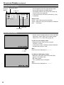
$XGLROHYHOPHWHUGLVSOD\
Channel
display
Reference point
0 dB point
1
3
5
7
2
4
6
8
A color skeleton bar meter indicates the audio
level for SDI signals and HDMI signals.
The display method of the audio level meter can
be set in the menu (page 49).
In 3D assist mode, the audio of the SDI1 (L) side
is indicated.
'LVSOD\FRORU
Green: Up to reference point (included)
Yellow: Reference point (not included) to 0 dB point
Red:
Overrange
SDI1 1080/60i
Peak hold
Overrange
7LPHFRGH7&GLVSOD\
Use the menu to display the time code for HD-SDI
signal input. It also allows you to switch display
mode (VITC, LTC, VUB, LUB). (page 50)
,Q9,7&DQG/7&GLVSOD\PRGH
Displays the time code in hours: minutes:
seconds: or frames.
In drop-frame mode, a different delimiter between
seconds and frames is used.
( : ) NDF
( . ) DF
Note :
Read errors are displayed as “--:--:--:--”
,Q98%DQG/8%GLVSOD\PRGHV
BG8, BG7, BG6, BG5, BG4, BG3, BG2, BG1
appear in the stated order.
BG: binary group
The (:) delimiter does not appear.
Note :
Read errors are displayed as “--:--:--:--”
20
2QVFUHHQ'LVSOD\FRQWLQXHG
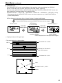
&ORVHGFDSWLRQ&&GLVSOD\
CLOSED CAPTION can be displayed when SDI
signals and VIDEO signals are input.
CLOSED CAPTION complies with the following
standards.
Composite Standard EIA/CEA-608 (VBI)
SD-SDI CC Standard EIA-608 (ANC)
HD-SDI CC Standard EIA-708
In the case of EIA-708, display is possible at a
position simultaneously specified for multiple
windows (up to 8).
The display position is within a display area that
is located inside the entire screen. (Refer to the
following notes.)
The display settings can be configured in the menus.
You can also select the type of CLOSED CAPTION,
display channel (EIA/CEA-608), and display service
(EIA/CEA-708) in the menus. (page 50)
Closed caption
display area
Closed caption
display area
(When the specified
window extends out of
the entire screen)
Notes:
The specified window position is displayed as a
position within the display area depending on the
CLOSED CAPTION information.
The window may extend out of the display area
depending on the specified window position and
size. In such a case, the window will be displayed
but if the window also extends out of the entire
screen, the display position of the window will be
changed so that the window is displayed inside
the entire screen.
'&SRZHUVXSSO\YROWDJHDQGEDWWHU\OHYHOGLVSOD\
DC power supply voltage is displayed.
The battery level display is displayed when the
battery you are using is an Anton/Bauer battery
with a battery level display function.
Displayed when the operating status display is not
displayed.
The display can be set in the menus. (page 34)
DC14.0V
50%
Notes:
The DC power voltage and battery level serve
as a near end warning indication as they flash
when the level falls to the value set in the menu or
lower.
Furthermore, when the level drops to less than
approximately 10.0 V, the “END BATTERY”
battery level error is displayed in red, and
the unit performs the shutdown process after
approximately 3 seconds have elapsed.
With some batteries, operation may be stopped
by an over discharge function of the battery
itself before the battery level error of the unit is
displayed.
We recommend replacing the battery as soon as
possible.
21
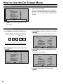
+RZWR8VHWKH2Q6FUHHQ0HQX
0HQXGLVSOD\
[MAIN MENU]
2D/3D ASSIST
MARKER
VIDEO CONFIG
SYSTEM CONFIG
VF CONFIG
FUNCTION
GPI
INPUT SELECT
DISPLAY SETUP
CONTROL
HOURS METER
MENU EXIT
This is the menu display.
The menu display disappears after 2 minutes of
inaction. (The setting values that were displayed
at the time that the menu display disappeared are
applied.)
2D
ENTER ENTER
SEL.
Displays the operation explanation for the
menu button.
0HQXRSHUDWLRQV
1. 3UHVV>0(18@WRGLVSOD\WKH0$,1PHQX
FUNCTION
1
INPUT
2
3
MENU
ENTER
2. 3UHVV> @> @WRVHOHFWDPHQXDQGSUHVV
>(17(5@
[MAIN MENU]
2D/3D ASSIST
MARKER
VIDEO CONFIG
SYSTEM CONFIG
VF CONFIG
FUNCTION
GPI
INPUT SELECT
DISPLAY SETUP
CONTROL
HOURS METER
MENU EXIT
SEL.
2D
3. 3UHVV> @> @WRVHOHFWDVXEPHQXDQGSUHVV
>(17(5@
The settings in the sub menu change to green.
[MARKER]
MARKER
16:9
4:3
BACK
CENTER
GPI MARKER1
GPI MARKER2
MARKER TYPE
CROSS HATCH
SIZE
MENU EXIT
SEL.
4. 3UHVV> @> @WRVHOHFWDVHWWLQJWKHQSUHVV
>(17(5@
To cancel, press [MENU].
[MARKER]
ENTER ENTER
OFF
4:3
OFF
NORMAL
OFF
95%(16:9)
95%(16:9)
TYPE 1
OFF
80
ENTER ENTER
MARKER
16:9
4:3
BACK
CENTER
GPI MARKER1
GPI MARKER2
MARKER TYPE
CROSS HATCH
SIZE
MENU EXIT
SEL.
ON
4:3
OFF
NORMAL
OFF
95%(16:9)
95%(16:9)
TYPE 1
OFF
80
ENTER ENTER
5. 7RUHWXUQWRWKHSUHYLRXVVFUHHQSUHVV
>0(18@
22
User Data
You can save and load up to five combinations of menu settings and adjustments made with the picture
adjustment knob as user data. You can also return settings and adjustments to their factory defaults. User
data include the following settings.
Menu settings except “SETUP LOAD/SAVE” and “REMOTE in CONTROL” (including button function
settings on the monitor front panel)
Screen adjustments made with the picture adjusting knob
6DYLQJXVHUGDWD
/RDGLQJXVHUGDWD
1. 3UHVV>0(18@WRGLVSOD\WKH0$,1PHQX
2. 3UHVV> @> @WRVHOHFWWKH³6<67(0&21),*´
PHQXDQGSUHVV>(17(5@
3. 3UHVV> @> @WRVHOHFWWKH³6(7836$9(´
VXEPHQXDQGSUHVV>(17(5@
The setting in the sub menu changes to green.
[SYSTEM CONFIG]
SUB WINDOW
MENU POSITION
STATUS DISPLAY
BATTERY REMAIN
WARNING VOLTAGE
SETUP LOAD
SETUP SAVE
POWER ON SETUP
COLOR SPACE
POWER SAVE MODE
CALIBRATION
AREA SETTING
MENU EXIT
SEL.
FULL
CENTER
3SEC OFF
OFF
TYPE1
FACTORY
USER1
LAST
EBU
OFF
▼
NTSC
ENTER ENTER
1. 3UHVV>0(18@WRGLVSOD\WKH0$,1PHQX
2. 3UHVV> @> @WRVHOHFWWKH³6<67(0&21),*´
PHQXDQGSUHVV>(17(5@
3. 3UHVV> @> @WRVHOHFWWKH³6(783/2$'´
VXEPHQXDQGSUHVV>(17(5@
The setting in the sub menu changes to green.
[SYSTEM CONFIG]
SUB WINDOW
MENU POSITION
STATUS DISPLAY
BATTERY REMAIN
WARNING VOLTAGE
SETUP LOAD
SETUP SAVE
POWER ON SETUP
COLOR SPACE
POWER SAVE MODE
CALIBRATION
AREA SETTING
MENU EXIT
SEL.
[SETUP SAVE]
4. 3UHVV> @> @WRVHOHFWD³86(5´WR³86(5´
ILOHWRORDGDQGSUHVV>(17(5@
The following screen appears.
To return to the factory defaults, select
“FACTORY.”
[SETUP LOAD]
USER1
YES
NO
MENU EXIT
SEL.
ENTER ENTER
Changes to green
Changes to green
4. 3UHVV> @> @WRVHOHFWD³86(5´WR³86(5´
ILOHWRVDYHWKHVHWWLQJVWRDQGSUHVV>(17(5@
The following screen appears.
FULL
CENTER
3SEC OFF
OFF
TYPE1
FACTORY
USER1
LAST
EBU
OFF
▼
NTSC
USER1
YES
NO
ENTER ENTER
5. 6HOHFW³<(6´DQGSUHVV>(17(5@
This saves the user data.
6. 7RUHWXUQWRWKHSUHYLRXVVFUHHQSUHVV
>0(18@
MENU EXIT
SEL.
ENTER ENTER
5. 6HOHFW³<(6´DQGSUHVV>(17(5@
This loads the user data.
6. 7RUHWXUQWRWKHSUHYLRXVVFUHHQSUHVV
>0(18@
23
0DLQ0HQX
0HQXFRQILJXUDWLRQ
MAIN MENU
2D/3D ASSIST
MARKER
MARKER
VIDEO CONFIG
SYSTEM CONFIG
16:9
GAMMA SELECT
SUB WINDOW
MENU POSITION
STATUS DISPLAY
BATTERY REMAIN
WARNING VOLTAGE
SETUP LOAD
SETUP SAVE
POWER ON SETUP
COLOR SPACE
POWER SAVE MODE
4:3
FILM GAMMA
BACK
COLOR TEMP.
CENTER
SHARPNESS MODE
GPI MARKER1
SHARPNESS H
GPI MARKER2
SHARPNESS V
MARKER TYPE
I-P MODE
CROSS HATCH
MONO
ANAMO
SD ASPECT
SCAN
SIZE
USER0-63
D93
D65
D56
CALIBRATION
WHITE BALANCE
VAR1
AUTO CALIBRATION
COLOR TEMP.
VAR2
RESET
GAIN
VAR3
AREA SETTING
RED
GREEN
VF CONTROL
VF CONFIG
BLUE
REAR TALLY
FUNCTION
FUNCTION1
ZEBRA
FUNCTION2
FUNCTION3
BIAS
GPI CONTROL
RED
GPI1
GREEN
GPI2
FUNCTION DISPLAY
BLUE
GPI3
RESET
GPI4
GPI
GPI5
INPUT SELECT
VIDEO
SELECT L
SELECT R
LEVEL METER
CH SELECT
POINT LINE
CH INFO.
HEAD ROOM
AUDIO
GPI7
NTSC SETUP
GPI8
SDI1
SDI2
HDMI
YPBPR
COMPONENT LEVEL
VF
VIDEO/ YPBPR
SIGNAL TYPE
INT SG
24
POSITION
VECTOR MODE
TIME CODE
CONTROL
LOCAL ENABLE
HOURS METER
WFM/VECTOR
VECTOR SCALE
DISPLAY SETUP
CONTROL
GPI6
FORMAT
MODE SELECT
CLOSED CAPTION
CC TYPE
OPERATION
CAPTION CHANNEL
LCD
CAPTION SERVICE
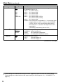
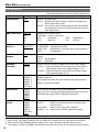
0DLQ0HQXFRQWLQXHG
2D/3D ASSIST
The underlined values are factory preset setting values.
6HWWLQJ
Description
2D
3D ASSIST
Switches between 2D mode and 3D assist mode.
<2D>
Operates in 2D mode.
<3D ASSIST> Operates in 3D assist mode.
If you switch to 3D assist mode, the channel setting is forcefully
switched to SDI1 (SDI2).
Use knob 4 to switch between each of the assist functions. (page
52)
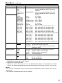
MARKER
The underlined values are factory preset setting values.
6XEPHQX
6HWWLQJV
MARKER
OFF
ON
16:9
*2*3
*1
OFF
4:3
13:9
14:9
CNSCO 2.39
CNSCO 2.35
2:1
VISTA
95%
93%
90%
88%
80%
USER 85%
Description
Enables the MARKER setting.
Selects/displays the marker type for when the angle of view of
the displayed image is 16:9.
<OFF> No marker display
<4:3>
4:3 marker
<13:9> 13:9 marker
<14:9> 14:9 marker
<CNSCO 2.39> 2.39:1 marker
<CNSCO 2.35> 2.35:1 marker
<2:1>
2:1 marker
<VISTA> VISTA marker
<95%> 95 % area marker
<90%> 90 % area marker
<80%> 80 % area marker
<93%> 93.1 % area marker (TYPE1)
93 % area marker (TYPE2)
<88%> 89.5 % area marker (TYPE1)
88 % area marker (TYPE2)
<USER> Area marker that is adjustable in 1 % increments within
a range of 80 % to 100 %. However, when MARKER
TYPE is TYPE1, 88 % becomes the aspect ratio of the
vertical 89 %.
(The factory preset setting value is 85 %.)
(Continued on next page)
*1
*2
*3
This setting is turned “ON” when receiving marker control in REMOTE operation. (GPI, if set, has
priority.)
These settings are disabled when the GPI function (page 62) is used to control the marker setting.
These settings are enabled when the SD aspect setting for an HD signal and SD signal is 16:9 ( “SD
ASPECT” on page 31).
25
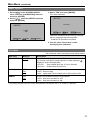
0DLQ0HQXFRQWLQXHG
6XEPHQX
4:3
*2*4
BACK
*2
CENTER
*2
6HWWLQJV
Description
OFF
95%
93%
90%
88%
80%
USER 85%
Selects/displays the marker type for when the angle of view of
the displayed image is 4:3.
<OFF> No marker display
<95%> 95 % area marker
<93%> 93 % area marker
<90%> 90 % area marker
<88%> 89 % area marker (TYPE1)
88 % area marker (TYPE2)
<80%> 80 % area marker
<USER> Area marker that is adjustable in 1 % increments within
a range of 80 % to 100 %. However, when MARKER
TYPE is TYPE1, 93 % becomes the aspect ratio of
the vertical 93.1 %, and 88 % the aspect ratio of the
vertical 89 %.
(The factory preset setting value is 85 %.)
NORMAL
HALF
BLACK
Selects the background brightness around the marker.
<NORMAL> Normal background
<HALF>
50 % background brightness
<BLACK>
0 % background brightness (black)
OFF
ON
Displays the center marker.
<OFF>
Turns the display off
<ON>
Turns the display on
(Continued on next page)
*2
*4
26
These settings are disabled when the GPI function (page 62) is used to control the marker setting.
7KHVHVHWWLQJVDUHHQDEOHGZKHQWKH6'DVSHFWVHWWLQJIRUDQ6'VLJQDOLVĺ³6'$63(&7´RQ
page 31).
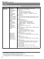
0DLQ0HQXFRQWLQXHG
6XEPHQX
GPI MARKER1
*5
GPI MARKER2
*5
MARKER TYPE
CROSS HATCH
SIZE
*5
*6
*6
6HWWLQJV
Description
4:3
13:9
14:9
CNSCO 2.39
CNSCO 2.35
2:1
VISTA
95% (16:9)
93% (16:9)
90% (16:9)
88% (16:9)
80% (16:9)
USER(16:9)
95% (4:3)
93% (4:3)
90% (4:3)
88% (4:3)
80% (4:3)
USER(4:3)
GPI MARKER1 : Selects the marker displayed by the GPI
terminal “MARKER1 ON/OFF” (page 62)
operation.
GPI MARKER2 : Selects the marker displayed by the GPI
terminal “MARKER2 ON/OFF” (page 62)
operation.
<4:3>
4:3 marker
<13:9>
13:9 marker
<14:9>
14:9 marker
<CNSCO 2.39> 2.39:1 marker
<CNSCO 2.35> 2.35:1 marker
<2:1>
2:1 marker
<VISTA>
VISTA marker
<95% (16:9) >
95% area marker for 16:9 aspect ratio
<93% (16:9) >
93% area marker for 16:9 aspect ratio
<90% (16:9) >
90% area marker for 16:9 aspect ratio
<88% (16:9) >
88% area marker for 16:9 aspect ratio
<80% (16:9) >
80% area marker for 16:9 aspect ratio
<USER (16:9) > User settings area marker for 16:9 aspect ratio
<95% (4:3) >
95% area marker for 4:3 aspect ratio
<93% (4:3) >
93% area marker for 4:3 aspect ratio
<90% (4:3) >
90% area marker for 4:3 aspect ratio
<88% (4:3) >
88% area marker for 4:3 aspect ratio
<80% (4:3) >
80% area marker for 4:3 aspect ratio
<USER (4:3) >
User settings area marker for 4:3 aspect ratio
TYPE1
TYPE2
Selects conventional monitor or camera recorder marker size.
<TYPE1> Conventional monitor marker size
<TYPE2> Marker size compliant with the camera recorder
(Panasonic made)
HIGH
LOW
OFF
Turns the cross hatch grid on and off and sets its density.
<HIGH>
Displays a bright cross hatch grid
<LOW>
Displays a dim cross hatch grid
<OFF>
Turns the display off
80
40
Selects the cross hatch grid size.
<80>
80 dots and 80 lines
<40>
40 dots and 40 lines
Remote control via RS-232C ends in error (error response: ER001) when “GPI MARKER1” or “GPI
MARKER2”is selected with the GPI function.
Display size for SD signals differ.
TYPE1: The effective horizontal area meets the SMPTE125M for NTSC and ITU-R BT. 601-5 for PAL.
TYPE2: The effective horizontal area meets the EIA-RS170A for NTSC and ITU-R BT. 470-4 for PAL.
<Notes>
The marker is not displayed during 2-screen display (SUB WINDOW), PIXEL TO PIXEL mode, and 3D
assist mode.
The marker is not displayed during VF line operation.
27
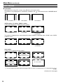
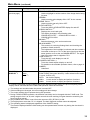
0DLQ0HQXFRQWLQXHG
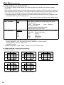
7\SHVRI0$5.(5
Ŷ PDUNHU
(Displayed when using HD, or when using SD with a 16:9 aspect ratio)
The marker is only displayed as a vertical bar. In addition, the
section becomes the “MARKER BACK”
item.
4:3 marker
13:9 marker
14:9 marker
9,67$PDUNHUPDUNHU&16&2PDUNHU
A horizontal dotted line is displayed as the marker.
VISTA marker
2:1 marker
CNSCO marker
(2.35/2.39)
The marker is displayed as a vertical dotted line when “UNDER” is selected under “SCAN” in the “VIDEO
CONFIG” menu.
VISTA marker
2:1 marker
CNSCO marker
(2.35/2.39)
$UHDPDUNHU
A dotted line is displayed as the marker.
TYPE1 Vertical 93.1 %
horizontal 93 %
TYPE2 Vertical/Horizontal 93 %
95 % Area marker
93 % Area marker
TYPE1 Vertical 89.5 %
Horizontal 88 %
TYPE2 Vertical/Horizontal 88 %
88 % Area marker
*1
90 % Area marker
95 % Area marker
80 % Area marker
USER Area marker *1
You can adjust the value within the range of 80 % to 100 % in increments of 1 % by pressing [ ][ ].
(Continued on next page)
28
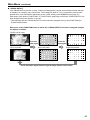
0DLQ0HQXFRQWLQXHG
Ŷ PDUNHU
(Displayed for SD input in 4:3 aspect ratio mode)
This marker is displayed as a dotted line.
95 % Area marker
93 % Area marker
88 % Area marker
80 % Area marker
90 % Area marker
(Displayed for HD input and SD input in 16:9 ratio mode.)
This marker is displayed as a dotted line.
95 % Area marker
93 % Area marker
90 % Area marker
TYPE1 Vertical 89 %
Horizontal 88 %
TYPE2 Vertical/Horizontal 88 %
88 % Area marker
*1
95 % Area marker
80 % Area marker
USER Area marker *1
You can adjust the value within the range of 80 % to 100 % in increments of 1 % by pressing [ ][ ].
<RXFDQGLVSOD\WKHPDUNHUDQGWKHPDUNHUVLPXOWDQHRXVO\
Simultaneous display example
The
section becomes the “MARKER BACK”.
It controls the background of the marker selected with a 16:9 ratio.
4:3 marker
16:9 marker
16:9 marker : 95 % area marker
4:3 marker : 80 % area marker
Ŷ &HQWHUPDUNHU
Center marker
This marker is displayed at the center of the screen.
29
0DLQ0HQXFRQWLQXHG
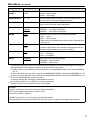
VIDEO CONFIG
The underlined values are factory preset setting values.
6XEPHQX
6HWWLQJV
Description
GAMMA
SELECT
STANDARD
FILM
STDIO/PST
Selects gamma curve.
<STANDARD> Standard mode
<FILM>
Film mode
<STDIO/PST> Color emphasis mode (a mode that
approximates CRT display capability suitable
for studio or postproduction application)
When FILM is selected, the
mark is displayed for the
*1
operating status.
FILM GAMMA
VARICAM
OTHER
Selects type of FILM gamma mode.
<VARICAM>
For VARICAM use
<OTHER>
Other
Brightness
(Gamma curve image)
OTHER
Video Gamma
VARICAM
Input Level
COLOR TEMP.
USER 0 - 63
D93
D65
D56
VAR1
VAR2
VAR3
*
2
Selects color temperature.
<USER 0 - 63> Adjustable settings 0 - 63
(equivalent to a color temperature range of
3,000 K - 9,300 K)
<D93>
Equivalent to a color temperature of 9,300 K
<D65>
Equivalent to a color temperature of 6,500 K
<D56>
Equivalent to a color temperature of 5,600 K
<VAR1> WB adjustment mode *3
<VAR2> WB adjustment mode *3
<VAR3> WB adjustment mode *3
(Continued on next page)
*1
*2
*3
30
In split-screen display, changes are not reflected to the still image in the main window.
When selecting USER 0 - 63
1) Push [ENTER] (USER changes to blue).
2) Select 0 - 63 with [ ], [ ] and push [ENTER].
Selecting “VAR1”, “VAR2” and “VAR3” engages the WB adjustment mode (page 32).
0DLQ0HQXFRQWLQXHG
6XEPHQX
6HWWLQJV
Description
SHARPNESS
MODE *4
HIGH
LOW
Selects the width of outline correction edge.
<HIGH> Narrow edge
<LOW> Wide edge
SHARPNESS H *4
0 - 30
Sets horizontal outline correction. The item display moves to
the lower part of the screen during adjustment.
SHARPNESS V *4
0 - 30
Sets vertical outline correction. The item display moves to the
lower part of the screen during adjustment.
MODE2
MODE1
Selects IP conversion mode. (see “IP mode” below.)
<MODE2> Intra-field interpolation
<MODE1> Intra-frame interpolation
OFF
ON
Switches between color and monochrome (MONO).
<OFF> Color
<ON>
Monochrome
* When ON, the CHROMA setting of the picture adjusting knob
is fixed at 0.
OFF
ON
With an Anamo lens and HD-SDI input, the picture is resized
to Anamo magnification (the vertically enlarged signal can be
vertically compressed and corrected for display).
4:3
16:9
Sets the aspect ratio for SD signal input.
<4:3> 4:3 display
<16:9> 16:9 display
NORMAL
UNDER
Sets under-scan and normal display.
<NORMAL> Normal display
<UNDER> Under-scan
I-P MODE
*5
MONO
ANAMO
*6
SD ASPECT
SCAN
*4
*5
*6
*6
The following sharpness values are available and the settings for the selected input signal is displayed.
Adjustment status during selection appears at the bottom left of the screen.
1) VIDEO system input (VIDEO) (the factory defaults are SHARPNESS MODE: LOW and SHARPNESS
H/V: 0)
2) HD for any other input (the factory defaults are SHARPNESS MODE: HIGH and SHARPNESS H/V: 0).
3) SD for any other input (the factory defaults are SHARPNESS MODE: LOW and SHARPNESS H/V: 0).
To use the “SUB WINDOW” (page 42) function,
1) Change settings after exiting the “SUB WINDOW” function.
2) It is recommended to use “MODE2” for handling fast video.
“SCAN” changes are not reflected in Anamo size display.
IP mode
“MODE1” performs IP conversion using intra-frame interpolation.
This monitor suppresses the delay to within 1 field.
The factory default is “MODE1”.
“MODE2” performs IP conversion using intra-field interpolation.
Since interpolation is performed inside each field, this mode is suitable for checking interlace status.
31
0DLQ0HQXFRQWLQXHG
Ŷ :%:+,7(%$/$1&(DGMXVWPHQWPRGH
Select “VAR1” to “VAR3” for “COLOR TEMP.” in the “VIDEO CONFIG” menu to make “WHITE BALANCE
VAR1” to “WHITE BALANCE VAR3” (WB) adjustments.
The underlined values are factory preset setting values.
6XEPHQX
6HWWLQJV
Description
COLOR TEMP.*1
USER 0 - 63
D93
D65
D56
Selects the color temperature that will become the basis
for adjustment.
<USER 0 - 63>
Adjustable settings 0 - 63 (equivalent
to a color temperature range of
3,000 K - 9,300 K)
<D93> Equivalent to a color temperature of 9,300 K
<D65> Equivalent to a color temperature of 6,500 K
<D56> Equivalent to a color temperature of 5,600 K
GAIN
ź
Adjusts the GAIN elements
Press [ENTER] to switch to RGB direct adjustment mode.
(This allows you to begin adjusting GAIN first.)
0 - 1023
(Factory defaults are
color temperature
<D65> values.)
*These are the
adjustments made
before shipment from
the factory.
Adjusts the GAIN elements for RED. (For numerical value
confirmation)
ź
Adjusts the BIAS elements
[Press [ENTER] to switch to RGB direct adjustment
mode.
(This allows you to begin adjusting BIAS first.)
- 512 - 511
(Factory default: 0)
Adjusts the BIAS elements for RED. (For numerical value
confirmation)
RED
GREEN
BLUE
BIAS
RED
32
Adjusts the GAIN elements for BLUE. (For numerical
value confirmation)
GREEN
Adjusts the BIAS elements for GREEN. (For numerical
value confirmation)
BLUE
Adjusts the BIAS elements for BLUE. (For numerical
value confirmation)
RESET
*1
Adjusts the GAIN elements for GREEN. (For numerical
value confirmation)
ź
Resets “GAIN RED” - “BIAS BLUE” to color temperature
values selected under “COLOR TEMP.”
Selecting “COLOR TEMP.” and pressing [ENTER] after making a change, opens a confirmation screen.
Selecting “YES” and pressing [ENTER] in this screen resets selected GAIN and BIAS values to the
selected color temperature values.
0DLQ0HQXFRQWLQXHG
Ŷ *$,1%,$65*%GLUHFWDGMXVWPHQWPRGH
If you press [ENTER] when the [GAIN] or [BIAS] item is selected in the WHITE BALANCE VAR (1 to 3)
menu, the screen switches to the one below and you can use the picture adjusting knobs to directly adjust
the RGB while checking the picture.
R is assigned to knob 1, G to knob 2, and B to knob 3.
If “WHITE BALANCE” is assigned to FUNCTION1 to FUNCTION3, this mode can also be accessed from
the FUNCTION buttons.
489
511
456
R-GAIN G-GAIN B-GAIN
F-IN-R
PEAK/
PHASE
CHROMA
VOLUME/
BRIGHT
CONT./
B.LIGHT
You can switch between GAIN and BIAS by
pressing the corresponding knob.
If you press [ENTER] in the [GAIN] menu, GAIN
adjustment is displayed first.
If you press [ENTER] in the [BIAS] menu, BIAS
adjustment is displayed first.
When you access the mode from a FUNCTION
button, GAIN adjustment is displayed first.
The adjustment item name and the numerical
value of the element is displayed above each of
the knobs.
Press the [MENU] button to return to menu
display. *1
If you switched the mode with a FUNCTION
button, display disappears if you press the
FUNCTION button. *1
*1
The same operation is also performed after 10
seconds of inaction.
33
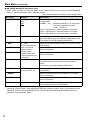
0DLQ0HQXFRQWLQXHG
SYSTEM CONFIG
The underlined values are factory preset setting values.
6XEPHQX
6HWWLQJV
Description
SUB WINDOW
FULL
PART
Selects sub-window type.
<FULL> Reduces the entire images for both input signals and
places them side by side.
<PART> Cuts out the center of the images for both input signals
and places them side by side (the images are shown at
their original size).
MENU POSITION
CENTER
LB
RB
RT
LT
Positions the on-screen menu.
<CENTER> Center of the screen
<LB>
Left Bottom
<RB>
<RT>
Right Top
<LT>
CONTINUE
3SEC OFF
OFF
Sets the display state of the operating status display (page 18).
<CONTINUE> Displayed at all times
<3SEC OFF>
Displayed for 3 seconds after a status change.*2
<OFF>
Not displayed.
BATTERY
REMAIN
OFF
ON
Selects whether DC power supply voltage and battery level
display.
<OFF> Not displayed.
<ON>
Displayed.
WARNING
VOLTAGE *3
TYPE1
TYPE2
Sets the near end warning voltage for the battery level display.
<TYPE1> Select this when you will mainly use an external DC
power supply. Near end is approximately 11.3 V.
<TYPE2> Select this when you will mainly use a battery. Near
end is approximately 13.3 V.
USER5 *4
USER4 *4
USER3 *4
USER2 *4
USER1 *4
FACTORY
Loads saved factory defaults (FACTORY) or user data (USER1 USER5) (page 23) .
After loading user data, the screen displays the signal selected
before user data was loaded.
SETUP SAVE
USER5
USER4
USER3
USER2
USER1
Up to 5 sets of user data can be saved (page 23).
They save menu settings and adjustments made with the picture
adjusting knob except “SETUP SAVE/SETUP LOAD.”
POWER ON
SETUP
USER5
USER4
USER3
USER2
USER1
FACTORY
LAST
Selects the settings used when the power is turned on.
<LAST>
Starts in the mode used when the power was
last turned off.
<FACTORY>
Starts up using the factory defaults.
<USER1 - 5> Starts up using USER registered settings.
STATUS
DISPLAY
*1
SETUP LOAD
*3
Right Bottom
Left Top
(Continued on next page)
*
*2
*3
*4
34
1
When PIXEL to PIXEL, operation is with CONTINUE regardless of the setting.
When PIXEL TO PIXEL/3D assist mode, the 3SEC OFF setting becomes equivalent to CONTINUE.
When the BATTERY REMAIN display setting is OFF, near end warning display does not occur.
The settings of USER1 to USER 5 and FACTORY are the same at the time of shipment from the factory.
0DLQ0HQXFRQWLQXHG
6XEPHQX
6HWWLQJV
Description
SMPTE-C
EBU
ITU-709 *6
Sets the studio standard color space.
POWER SAVE
MODE
OFF
ON
Sets the power save mode
<ON> The backlight dims when no signal (NO SIGNAL) is input
for 60 seconds or longer. Signal input or menu operation
will return the backlight to its normal brightness.
CALIBRATION
ź
Connect Display Color Analyzer CA-210 and then perform
calibration. This also allows you to restore the calibration data to
the factory preset setting values.
(pages 35, 36, and 37)
AREA SETTING
NTSC
NTSC (J)
PAL
Selects the area of the unit.
ĺ³6HOHFWLQJ$UHDRI8VH´RQSDJH
The setting does not vary depending on the operation of SETUP
LOAD or POWER ON SETUP.
COLOR SPACE
*5
*5 The factory preset setting value varies depending on the area set in “AREA SETTING”.
*6 ITU-709 indicates the ITU-R BT.709 standard.
Ŷ CALIBRATION
The CALIBRATION function in this unit measures LCD panel characteristics from low to high brightness
values and internal monitor processing handles CALIBRATION.
CALIBRATION does not rely on image quality settings since internal signals are used for a calibration.
CALIBRATION in this unit is made at D65 color temperature and other color temperatures are results
calculated automatically from this value.
Ŷ (TXLSPHQWUHTXLUHGIRUFDOLEUDWLRQ
Konica Minolta CA-210
Analyzer Side
(Straight)
This unit Side
or CA-310 display color
3LQQXPEHU 6LJQDO
3LQQXPEHU 6LJQDO
analyzer
1
CD
1
N.C.
Konica Minolta CA6(5,$/7HUPLQDO3
2
TXD
2
RXD
PU12 or CA-PU15
3
RXD
3
TXD
standard measurement probe
4
DSR
4
DTR
A RS-232C cable (male to male, straight)
5
GND
5
GND
Connect the SERIAL terminal on this unit to the RS6
DTR
6
DSR
232C terminal on the display color analyzer using a
7
CTS
7
RTS
straight cable.
8
RTS
8
CTS
9
GND
9
N.C.
This unit
Konica Minolta CA-PU12 or CA-PU15
standard measurement probe
Konica Minolta CA-210 or CA-310 display
color analyzer
RS-232C cable
(Continued on next page)
35
0DLQ0HQXFRQWLQXHG
When using the CA-210 display color analyzer,
Compensation
W
R
G
B
be sure to set the compensation values shown
x
0.296
0.6534 0.2851 0.1485
on the right. If they are not set, correct calibration
y
0.3036 0.3271 0.5927 0.0523
will not be performed. For details on setup
Lv
203.4
43.18
148.1
15.5
procedures, refer to the CA-210 User's Guide.
There is no compensation when using Display Color Analyzer CA-310.
Turn on this unit and perform adequate aging (about 1 hour) before starting calibration.
Make the room dark so that no external light can enter the standard measurement probe before starting
the calibration. If external light enters the probe, the low brightness characteristics may not be calibrated
correctly.
LCD panel characteristics and instrument error in the display color analyzer may sometimes result in small
differences in values after calibration.
In a fine tuning of the monitor, also set GAIN and BIAS for R, G and B in the COLOR TEMP. VAR mode.
Do not apply the probe to a WFM/VECTOR display on the screen.
Ŷ CALIBRATION
Select CALIBRATION in the “SYSTEM CONFIG” menu to open the following menus.
6XEPHQX
AUTO CALIBRATION
RESET
*1
*2
*
1
*2
6HWWLQJV
Description
ź
Connect a CA-210 Display color analyzer and use this
submenu to make a calibration.
Select “AUTO CALIBRATION” and select “YES” in the
confirmation screen that appears to start calibration.
ź
Returns calibration data to their factory defaults.
Select “RESET” and select “YES” in the confirmation screen
that appears to return calibrated values to their factory defaults.
“EXECUTING” is displayed during “AUTO CALIBRATION” and “COMPLETE” appears when calibration
ends. “INCOMPLETE” appears if calibration could not be completed.
When “RESET” ends, “COMPLETE” appears.
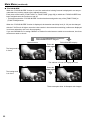
3HUIRUPLQJ$872&$/,%5$7,21
1. 3UHVV> @> @LQWKH³6<67(0&21),*´
PHQXVHOHFWWKH>&$/,%5$7,21@VXEPHQX
DQGSUHVV>(17(5@
2. 3UHVV> @> @VHOHFWWKH>$872
&$/,%5$7,21@VXEPHQXDQGSUHVV>(17(5@
3. 6HOHFW³<(6´DQGSUHVV>(17(5@
This starts calibration.
[AUTO CALIBRATION]
xxxxxxxx
[AUTO CALIBRATION]
YES
NO
MENU EXIT
SEL.
MENU EXIT
ENTER ENTER
SEL.
ENTER ENTER
xxxxxxxxx indicates that one of the following
messages with the meaning listed below
appears.
EXECUTING: Operation in progress
COMPLETE: Operation completed
INCOMPLETE: Operation incompleted.
(Check the SERIAL connection or display color
analyzer connection.)
4. 7XUQWKHSRZHURIIDQGWKHQRQDIWHU
SHUIRUPLQJDXWRFDOLEUDWLRQ
36
0DLQ0HQXFRQWLQXHG
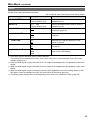
RESET operation
1. 3UHVV> @> @LQWKH³6<67(0&21),*´
PHQXVHOHFWWKH>&$/,%5$7,21@VXEPHQX
DQGSUHVV>(17(5@
3. 6HOHFW³<(6´DQGSUHVV>(17(5@
This starts calibration.
[RESET]
2. 3UHVV> @> @VHOHFWWKH>5(6(7@VXEPHQX
DQGSUHVV>(17(5@
xxxxxxxx
[RESET]
YES
NO
MENU EXIT
SEL.
MENU EXIT
SEL.
ENTER ENTER
xxxxxxxxx indicates that the following message
with the meaning listed below appears.
COMPLETE: Operation completed
ENTER ENTER
4. 7XUQWKHSRZHURIIDQGWKHQRQDIWHU
SHUIRUPLQJDXWRFDOLEUDWLRQ
VF CONFIG
The underlined values are factory preset setting values.
6XEPHQX
6HWWLQJV
Description
VF CONTROL
VF-CH
ALL-CH
Used to select the input line for the VF function of the monitor.
(VF function: tally lamps (red and green) lit, zebra displayed, !
displayed, aspect changed [SD])
<VF-CH>
Only enabled when the VF line is selected.
<ALL-CH> Enabled with all input lines.
REAR TALLY
OFF
ON
Used to allow control of the tally lamp on the rear of the monitor.
<OFF> Does not light.
<ON> Lights when TALLY control from a GPI/camera is ON.
ZEBRA
OFF
ON
Used to set ZEBRA information in the camera.
<OFF> Sets the information to OFF.
<ON> Sets the information to ON.
The priority sequence for GPI control and SERIAL is as follows: GPI > VF CONFIG > SERIAL.
37
0DLQ0HQXFRQWLQXHG
FUNCTION
The underlined values are factory preset setting values.
6XEPHQX
6HWWLQJV
Description
FUNCTION 1 FUNCTION 3
HV DELAY
BLUE ONLY
GAMMA SELECT
SD ASPECT
SCAN
SUB WINDOW
WFM/VECTOR
MARKER
WHITE BALANCE
PIXEL TO PIXEL
PIXEL POSITION
FOCUS-IN-RED
ZEBRA
REAR TALLY
LEVEL METER
CROSS HATCH
MONO
BLACK MODE
TIME CODE
CLOSED CAPTION
UNDEF
Selects functions to be assigned to [FUNCTION1] [FUNCTION3] (front panel buttons).
<HV DELAY> *1
Displays the image blanking period.
The display changes in the following order.
'(/$<2))ĺ+'(/$<ĺ9'(/$<ĺ+9'(/$<ĺ
DELAY OFF
<BLUE ONLY> *1
Cuts the red and green signals. Use this function to check
phase and chroma. This button toggles between ON and
OFF.
<GAMMA SELECT>*2*3
Displays the gamma curve.
The display changes in the following order.
*$00$67$1'$5'ĺ*$00$),/0ĺ
*$00$67',2367ĺ*$00$67$1'$5'
<SD ASPECT> *2 *3
Switches between “16:9” and “4:3.”
<SCAN> *2*3
Switches between “UNDER SCAN” and “NORMAL SCAN”.
<SUB WINDOW> *1
Sets the split-screen function.
The display changes in the following order.
6,1*/(ĺ)8//3$57ĺ67,//ĺ6,1*/(
<WFM/VECTOR> *2
Displays waveform or vector display.
For details on the available operation items, refer to page
41.
<MARKER> *2*3*4
Turns the marker on and off.
For details on the available operation items, refer to page
41.
<WHITE BALANCE>
WHITE BALANCE GAIN/BIAS RGB direct adjustment can
only be accessed when VAR1 to VAR3 are selected in
COLOR TEMP.
<PIXEL TO PIXEL>
Turns the PIXEL TO PIXEL function On and Off.
<PIXEL POSITION>
Positions the display of signals in PIXEL TO PIXEL mode.
(Factory default:
FUNCTION1:
WFM/VECTOR
FUNCTION2:
PIXEL TO PIXEL
FUNCTION3:
FOCUS-IN-RED)
(Continued on next page)
*1
*2
*3
*4
38
The settings are cancelled when the power is turned OFF.
If these settings are changed, the menu settings will also change.
The control settings do not operate during GPI operation.
Not displayed when 16:9, 4:3 and CENTER are all OFF in the MARKER menu settings.
0DLQ0HQXFRQWLQXHG
6XEPHQX
6HWWLQJV
FUNCTION
DISPLAY *8
Description
<FOCUS-IN-RED>*3*5
Used to highlight in red the section of the image that is being
focused.
<ZEBRA>
Used to set the zebra display ON or OFF for the camera.
<REAR TALLY> *2*6
Used to set the rear tally ON or OFF.
<LEVEL METER> *2
Turns the AUDIO LEVEL METER display On and Off.
<CROSS HATCH> *2
Displays the cross hatch grid.
The display changes in the following order.
&5266+$7&+2))ĺ&5266+$7&+/2:ĺ
CROSS HATCH HIGH
<MONO> *2*3
Switches between color and monochrome.
<BLACK MODE> *1 *7
This mode is for reducing floating black and checking the
gradation of dark sections.
The brightness of the backlight is reduced and the contrast is
increased so that up to 75 % of the input signal level has the
same gamma curve as the set GAMMA SELECT. The signal
level on or above that is clipped at 75 %.
<TIME CODE> *2
Turns the time code display on and off.
<CLOSED CAPTION> *2
Turns the closed caption display on and off.
For details on the available operation items, refer to page 41.
<UNDEF>
Undefined
(From the
previous page)
OFF
ON1
ON2
*9
Selects display of functions assigned to [FUNCTION1] [FUNCTION3] (front panel buttons). It also selects button action
(1- touch, 2-touch, off).
<OFF> No function display.
<ON1> 1-touch action to display and perform functions.
<ON2> 2-touch action to display and perform functions.
If a FUNCTION button is pushed during the picture adjusting knobs display, the picture adjusting knobs
display will be cancelled and the FUNCTION operation cannot be executed.
*1
*2
*3
*5
*6
*7
*8
*9
The settings are cancelled when the power is turned OFF.
If these settings are changed, the menu settings will also change.
The control settings do not operate during GPI operation.
During FOCUS-IN-RED operation, the detection sensitivity can be changed with the F-IN-R knob. The
setting range is from 0 to 30, with a higher numerical value resulting in higher detection sensitivity (the
focus becomes worse).
Only enabled when TALLY control from the camera or GPI (R-TALLY) is ON.
The bright picture more than 75 % is clipped. The back light and contrast cannot be adjusted.
The operating status is displayed regardless of the ON/OFF setting.
The function displayed with the ON2 setting can be operated with a button only during the time that it is
displayed.
39
0DLQ0HQXFRQWLQXHG
Ŷ )81&7,21VHWWLQJUHVWULFWLRQV
Under the following conditions, “INVALID FUNCTION” is displayed and the settings cannot be configured.
6HWWLQJV
Inoperable Condition or Mode
HV DELAY
GAMMA SELECT
When GPI is set
When HDMI (640 x 480) input
SD ASPECT
When GPI is set
SUB WINDOW (Still image)
3D ASSIST
When HDMI (640 x 480) input
SCAN
When GPI is set
SUB WINDOW
PIXEL TO PIXEL
3D ASSIST
When HDMI (640 x 480) input
SUB WINDOW
3D ASSIST
When HDMI (640 x 480) input
WFM/VECTOR
(VECTOR is not displayed when other than SDI1 or SDI2 input)
SUB WINDOW
PIXEL TO PIXEL
3D ASSIST
When HDMI (640 x 480) input
MARKER
WHITE BALANCE
When other than VAR1 to VAR3 selected in COLOR TEMP.
PIXEL TO PIXEL
(Enabled when 1080i/p signal input)
When other than 1080i/p signal input
SUB WINDOW
3D ASSIST
FOCUS-IN-RED
When WFM is ON
When GPI is set
When INT-SG is selected
LEVEL METER
When other than SDI1, SDI2, or HDMI input
MONO
When GPI is set
When HDMI (640 x 480) input
TIMECODE
When other than HD-SDI input
CLOSED CAPTION
SUB WINDOW
WFM
PIXEL TO PIXEL
3D ASSIST
When HDMI (640 x 480) input
When GPI is set
SUB WINDOW
3D ASSIST
When HDMI (640 x 480) input
When HDMI (640 x 480) input
When VF signal input
When YPBPR signal input
3D ASSIST
The function assigned to FUNCTION3 does not work when you operate the unit in 3D assist mode
because the FUNCTION3 button becomes specifically for switching to 2D picture adjustment mode (2D
ADJUST).
40
0DLQ0HQXFRQWLQXHG
Ŷ )XQFWLRQVGLVSOD\HGGXULQJ)81&7,21EXWWRQRSHUDWLRQ
Pressing any of the [FUNCTION1] to [FUNCTION3] buttons displays the operations assigned to each
button as shown below.
HV DELAY
DELAY OFF/H DELAY/V DELAY/
HV DELAY
BLUE ONLY
BLUE ONLY ON/BLUE ONLY OFF
GAMMA SELECT
GAMMA STANDARD/GAMMA FILM/
GAMMA STDIO/PST
SD ASPECT
4:3/16:9
SCAN
NORMAL SCAN/UNDER SCAN
SUB WINDOW
SINGLE/FULL/PART/STILL
WFM/VECTOR
WFM/VECTOR OFF/WFM Y ON/
WFM R ON/WFM G ON/WFM B ON/
9(&725î9(&725î69(&725î
9(&725î9(&725î
MARKER
MARKER OFF/4:3 MARKER/
13:9 MARKER/14:9 MARKER/
CNSCO2.39 MARKER/
CNSCO2.35 MARKER/
2:1 MARKER/VISTA MARKER/
95% MARKER/93% MARKER/
90% MARKER/88% MARKER/
80% MARKER/
xx% MARKER (xx % is a USER setting value of
80 % to 100 %)/MARKER ON
When the setting values of both 16:9 and 4:3
are set to other than OFF in the MARKER
menu settings, the setting value of 16:9 is
displayed in the first half section, and the
setting value of 4:3 is displayed in the second
half section.
PIXEL TO PIXEL
PIXEL TO PIXEL OFF/
PIXEL TO PIXEL CENTER/
PIXEL TO PIXEL LT/
PIXEL TO PIXEL RT/
PIXEL TO PIXEL RB/
PIXEL TO PIXEL LB
PIXEL POSITION
PIXEL TO PIXEL OFF/
PIXEL TO PIXEL CENTER/
PIXEL TO PIXEL LT/
PIXEL TO PIXEL RT/
PIXEL TO PIXEL RB/
PIXEL TO PIXEL LB
FOCUS-IN-RED
FOCUS-IN-RED OFF/FOCUS-IN-RED ON
ZEBRA
ZEBRA OFF/ZEBRA ON
REAR TALLY
REAR TALLY OFF/ REAR TALLY ON
LEVEL METER
METER OFF/METER 2CH/METER 4CH/
METER 8CH
CROSS HATCH
CROSS HATCH HIGH/
CROSS HATCH LOW/
CROSS HATCH OFF
MONO
MONO ON/MONO OFF
TIME CODE
LTC/VITC/LUB/VUB/TC OFF
BLACK MODE
BLACK MODE OFF/BLACK MODE ON
CLOSED CAPTION
CC1/CC2/CC3/CC4/CC OFF
(SRV1/SRV2/SRV3/SRV4/SRV5/
SRV6/CC OFF)
* The displayed items differ depending on the
selection for CC TYPE.
2D ADJUST
2D ADJUST OFF/2D ADJUST ON
<Note>
WHITE BALANCE is switched to adjustment mode
with a FUNCTION button, and the indication that
indicates the operation is not displayed.
Ŷ ³+9'(/$<´
This displays the blanking period. Each press of the button changes the display as follows: H blanking
GLVSOD\ĺ9EODQNLQJGLVSOD\ĺ+DQG9EODQNLQJGLVSOD\ĺQREODQNLQJGLVSOD\
41
0DLQ0HQXFRQWLQXHG
Ŷ ³68%:,1'2:´
Opening the “SUB WINDOW” function splits the screen (main window) in two as shown below to enable
comparison of a recorded still image with live video.
Use the “SUB WINDOW” setting (FULL, PART) in the “SYSTEM CONFIG” menu (page 34) to set up the
function as shown below.
Press the button ([FUNCTION1] to [FUNCTION3] (page 38)) to which the “SUB WINDOW” function has
been assigned to turn the function on and off.
This assumes that the “SUB WINDOW” function has been assigned to any of the [FUNCTION1] to
[FUNCTION3] buttons.
To setup “I-P MODE” (page 31), exit the “SUB WINDOW” function first.
FULL
Resizes the main window to also display a second window (two sub-windows).
Press the FUNCTION button to which the SUB WINDOW function has been assigned.
Normal window
(main window)
Before memory
(two sub-windows)
Press the
EXWWRQDJDLQ
Press the
EXWWRQDJDLQ
Video
Video
After memory
(two sub-windows)
Video
6WLOOLPDJH
Video
(Left side is stored
in memory.)
PART
Resizes the main window to show only its center to also display a second image (two sub-windows).
Press the FUNCTION button to which the SUB WINDOW function has been assigned.
Normal window
(main window)
Before memory
(two sub-windows)
Press the
EXWWRQDJDLQ
Press the
EXWWRQDJDLQ
Video
Crops the image to show its
center part
After memory
(two sub-windows)
Video
Video
The cropped main window
image is placed side by side
with a second image
6WLOOLPDJH
Video
(Left side is stored
in memory.)
These examples show 16:9 aspect ratio images.
Note on FULL/PART selection
This function is designed to enable comparison of identical formats input to the same input terminal. Input
of different formats via different input channels may distort the sub-window (left side, still image) or blanking
could occur. However, input of an identical format signal to the input terminal during still image acquisition
will display correctly.
42
0DLQ0HQXFRQWLQXHG
Ŷ ³:)09(&725´
The “WFM/VECTOR” function enables display of the waveform and vector display. Use “DISPLAY
SETUP” in the main menu to select “WFM” and “VECTOR” display. (page 50)
Press the button ([FUNCTION1] to [FUNCTION3] (page 39)) to which the “WFM/VECTOR” function has
been assigned to switch the display in the following order.
:)09(&7252))ĺ:)0<21ĺ:)0521ĺ:)0*21ĺ:)0%21ĺ9(&725[WR[
This assumes that the “WFM/VECTOR” function has been assigned to any of the [FUNCTION1] to
[FUNCTION3] buttons.
WFM is displayed in the order of the Y signal, R signal, G signal, and B signal.
Press the FUNCTION button to which the WFM/VECTOR function has been assigned.
WFM display
<ĺ5ĺ*ĺ%
Normal screen
VECTOR display
Press the
EXWWRQDJDLQ
*1
Press the
EXWWRQDJDLQ
WFM
(waveform display)
VECTOR
(vector display)
These examples show 16:9 aspect ratio images.
*1
Displayed only for SDI signal input.
The scale display is as shown below.
This dotted line is 109%.
100 %
50 %
A dotted line indicates for
each 10% increase.
0%
This dotted line is -4%.
I axis
The frame is ±2.5°, ±2.5 %
Q axis
43
0DLQ0HQXFRQWLQXHG
Ŷ ³3,;(/723,;(/´DQG³3,;(/326,7,21´
The “PIXEL TO PIXEL” function allows you to check images at their actual pixel resolution (1080i/p
signals only).
Press the button ([FUNCTION1] to [FUNCTION3] (page 38)) to which the “PIXEL TO PIXEL” function has
been assigned to turn the function on. Then press the button ([FUNCTION1] to [FUNCTION3] (page 38))
to which the “PIXEL POSITION” function has been assigned to position the display of signals.
This assumes that the “PIXEL TO PIXEL” and “PIXEL POSITION” functions have been assigned to any
of the [FUNCTION1] to [FUNCTION3] buttons.
The underlined values are factory preset setting values.
Item
6HWWLQJV
Description
PIXEL TO PIXEL*1*2
OFF
ON
Sets whether to display the screen display size at the
input signal size.
<OFF> Not displayed.
<ON> Displayed.
Compatible formats
1080/60i/59i/50i/60p/59p/50p/30p/29p/
25p/24p/23p/25PsF/24PsF/23PsF
PIXEL POSITION
CENTER
LT
RT
RB
LB
Positions the display of signals in PIXEL TO PIXEL mode.
<CENTER> Center of the screen
<LT>
Left Top
<RT>
Right Top
<RB>
Right Bottom
<LB>
Left Bottom
*1
*2
The following settings are disabled in PIXEL TO PIXEL mode.
Setting “ANAMO” to “ON”, and setting “SCAN” to “UNDER” in “VIDEO CONFIG”
Any “HV DELAY” setting in “FUNCTION”
“MARKER” display
Enabled during “SDI1”, “SDI2”, “HDMI”, “YPBPR” and “VF (VF-YPBPR)” input.
Ŷ ³3,;(/326,7,21´GLVSOD\SRVLWLRQVHTXHQFH
PIXEL POSITION: cĺdĺeĺfĺgĺc .....
44
c CENTER
d LT (LEFT TOP)
f RB (RIGHT BOTTOM)
g LB (LEFT BOTTOM)
e RT (RIGHT TOP)
0DLQ0HQXFRQWLQXHG
Ŷ ³&5266+$7&+´
If the CROSS HATCH function is used, markers are displayed at regular vertical and horizontal intervals
to facilitate, for example, easy composition. The marker line width is 1 dot /1 line and the interval is 80
dots/80 lines or 40 dots/40 lines depending on the “SIZE” setting in the MARKER menu (page 27).
Each press of the button (“FUNCTION1” to “FUNCTION3” (page 38)) to which the “CROSS HATCH” has
been assigned turns the function on and off.
This assumes that the “CROSS HATCH” function has been assigned to any of the [FUNCTION1] to
[FUNCTION3] buttons.
(DFKSUHVVRIWKH)81&7,21EXWWRQWRZKLFKWKH³&5266+$7&+´IXQFWLRQLVDVVLJQHGFKDQJHV
WKHGLVSOD\DVVKRZQ
HD/SD (16:9) mode
Press the
EXWWRQDJDLQ
SD (4:3) mode
Press the
EXWWRQDJDLQ
Dim cross hatch
Bright cross hatch
3UHVVWKHEXWWRQDJDLQEDFNWRRULJLQDOLPDJHZLWKRXWFURVVKDWFK
45
0DLQ0HQXFRQWLQXHG
Ŷ ³)2&86,15('´
When the “FOCUS-IN-RED” function is used, the section that is being focused is displayed in an easy-tounderstand red, making camera focus adjustments easy.
Each press of the button (“FUNCTION1” to “FUNCTION3” (page 38)) to which the “FOCUS-IN-RED” has
been assigned turns the function on and off.
This assumes that the “FOCUS-IN-RED” function has been assigned to any of the [FUNCTION1] to
[FUNCTION3] buttons.
When the “FOCUS-IN-RED” function is displayed, the detection sensitivity level (0 - 30) can be changed
with the F-IN-R knob. A higher numerical value results in lower detection sensitivity (outlines are displayed
in red even when they are not in focus properly).
If you set CHROMA to 0 or assign "MONO" to another function button to switch to monochrome, the focus
will become easier to check.
3XVKRQFHWKH)81&7,21EXWWRQWRZKLFKWKH
)2&86,15('IXQFWLRQLVDVVLJQHG
Normal screen
FOCUS-IN-RED display
Press the
EXWWRQDJDLQ
The foreground is
in focus
The outlines in focus are displayed in red
Press the
EXWWRQDJDLQ
The background
is in focus
These examples show 16:9 aspect ratio images.
46
0DLQ0HQXFRQWLQXHG
GPI
“GPI CONTROL” is used to enable and disable GPI functions and assign functions to each of the GPI
terminal pins (page 62).
The underlined values are factory preset setting values.
6XEPHQX
6HWWLQJV
Description
GPI CONTROL
DISABLE
ENABLE
Enables and disables GPI functions
<DISABLE> Disabled
<ENABLE>
Enabled
GPI1 - GPI8
UNDEF
MARKER1 ON/OFF
MARKER2 ON/OFF
MARKER BACK HALF
MARKER BACK BLACK
CENTER MARKER
INPUT SEL. VIDEO
INPUT SEL. SDI1
INPUT SEL. SDI2
INPUT SEL. HDMI
INPUT SEL. YPBPR
INPUT SEL. VF
INPUT SEL. INT SG
SD ASPECT
SCAN
R-TALLY
G-TALLY
MONO
GAMMA SEL. FILM
GAMMA SEL. STDIO/PST
PIXEL TO PIXEL
FOCUS-IN-RED
REMOTE STANDBY
Assigns functions to the GPI control terminal pins.
The same items can be set to each terminal (page
62).
Note:
Operation may not be possible depending on the setting conditions.
Example: “SD ASPECT” operation when input signal is HD
47
0DLQ0HQXFRQWLQXHG
INPUT SELECT
The underlined values are factory preset setting values.
6XEPHQX
6HWWLQJV
Description
VIDEO
OFF
ON
Sets or cancels VIDEO line for the INPUT button.*1
FORMAT
AUTO
NTSC
PAL
Used to select the format for VIDEO input.*2
<AUTO> NTSC or PAL is selected automatically.
<NTSC> NTSC
<PAL> PAL
NTSC SETUP
75
00
Selects NTSC setup level.
<75>
Select this function when using 7.5 % setup signals.
(Adjusts the interior of the monitor to the 7.5 % setup level
to suit the black level)
<00>
Select this when the signal is at a 0 IRE setup level.
SDI1
OFF
ON
Sets or cancels SDI1 line for the INPUT button.*1
SDI2
OFF
ON
Sets or cancels SDI2 line for the INPUT button.*1
HDMI
OFF
ON
Sets or cancels HDMI line for the INPUT button.*1
YPBPR
OFF
ON
Sets or cancels YPBPR line for the INPUT button.*1
SMPTE
B75
B00
Selects YPBPR (component) signal input level.
<SMPTE> Signal level complies with SMPTE and PB and PR are 0.7
V #p-p] at 100 % chroma.
<B75>
Select this when connecting a Betacam or similar
device with a setup function. (Adjusts the interior of the
monitor to the 7.5 % setup level to suit the black level)
<B00>
Select this when connecting a Betacam or similar
device without a setup function.
OFF
ON
Sets or cancels VF line for the INPUT button.*1
VIDEO/YPBPR
VIDEO
YPBPR
Used to select the VF input mode.
<VIDEO> Selects the VIDEO signal.
<YPBPR> Selects the YPBPR (component) signal.
SIGNAL TYPE
HD
SD
Used to select the signal output from the camera.
<HD>
Selects the HD signal.
<SD>
Selects the SD signal.
OFF
ON
Sets or cancels INT SG line for the INPUT button.*1
COMPONENT
LEVEL
VF
INT SG
*1
*2
48
All of the seven input lines (VIDEO, SDI1, SDI2, HDMI, YPBPR, VF, and INT SG) cannot be set to OFF. If
six of the input lines are set to OFF, the one remaining input line cannot be set to OFF.
“AUTO” is the factory default, but select a specific format when there is risk that the input signal may be
interrupted by outside noise.
0DLQ0HQXFRQWLQXHG
AUDIO
Set the audio output and audio level meter.
The underlined values are factory preset setting values.
6HWWLQJV
Description
SELECT L
6XEPHQX
*1 *2
CH1 - CH8
(Factory default: CH1)
Selects embedded audio channel output to
headphones (L).
SELECT R
*1 *3
CH1 - CH8
(Factory default: CH2)
Selects embedded audio channel output to
headphones (R).
OFF
ON
Selects embedded audio level meter
displayed. (page 20)
8CH
4CH
2CH
Selects number of audio level meter
channels.
POINT LINE
OFF
ON
Switches the 0 dB line displayed on the
meter on and off.
CH INFO.
OFF
ON
Switches the channel displayed on the meter
on and off.
12dB
18dB
20dB
Sets the display position of the reference
point in the meter display.
LEVEL METER
CH SELECT
*4
HEAD ROOM
*1
*2
*3
*4
*5
*5
If the input signal is SD when CH5 to CH8 is selected:
7KHFKDQQHOFDQEHVZLWFKHGIURP&+ĺ&+&+ĺ&+&+ĺ&+DQG&+ĺ&+7KHPHQX
settings remain as is.)
When an HDMI signal is input, the audio of CH1 is output to the headphones (L) regardless of the menu
setting.
When an HDMI signal is input, the audio of CH2 is output to the headphones (R) regardless of the menu
setting.
When an HDMI signal is input, the display becomes 2CH regardless of the menu setting. When an SDSDI signal is input, the display becomes 4CH even if 8CH is selected in the menu.
The factory preset setting value varies depending on the area set in “AREA SETTING” (page 35).
49
0DLQ0HQXFRQWLQXHG
DISPLAY SETUP
The underlined values are factory preset setting values.
6XEPHQX
6HWWLQJV
Description
WFM/VECTOR
OFF
WFM Y
WFM R
WFM G
WFM B
VECTOR
Switches between “WFM/VECTOR” waveform and vector display.
<WFM Y> - <WFM B> Displays waveforms.
<VECTOR>
Displays vector waveforms.*1
POSITION
LB
RB
RT
LT
Selects the position for the “WFM/VECTOR” waveform display.*1
<LB>
Left Bottom
<RB>
Right Bottom
<RT>
Right Top
<LT>
Left Top
VECTOR MODE
î
î
î
î6
î
Enlarges vector waveforms.*1
î! î
î! î
î! î
î6! 6WDWHLQZKLFKGLVSOD\HGDWVFDOHRI[DQGRQO\
waveforms enlarged to 2 x.
î! î
VECTOR SCALE
100%
75%
Determines the scale of vector waveform.
<100%> Displays it at 100 % scale.
<75%> Displays it at 75 % scale.
OFF
ON
Turns the time code display on and off.
LTC
VITC
LUB
VUB
Selects time code display mode.
<LTC>
Displays linear time code (LTC).
<VITC> Displays vertical interval time code (VITC).
<LUB> Displays user bits included in LTC.
<VUB> Displays user bits included in VITC.
OFF
ON
Turns closed caption display on and off.*2
CC TYPE
CEA-608
CEA-708
Selects the closed caption display mode.
<CEA-608> Displays data compliant with CEA-608.
<CEA-708> Displays data compliant with CEA-708.
CAPTION
CHANNEL
CC4
CC3
CC2
CC1
Selects the closed caption display channel for when CEA-608.
CAPTION
SERVICE
SRV6
SRV5
SRV4
SRV3
SRV2
SRV1
Selects the closed caption display service for when CEA-708.
TIME CODE
MODE SELECT
CLOSED CAPTION
*1
*2
50
Opens the vector display during SDI signal input.
Available during VIDEO input. Closed captions appear as bright lines on line 21 when closed caption is
set to ON and underscan is also on.
0DLQ0HQXFRQWLQXHG
CONTROL
The underlined values are factory preset setting values.
6XEPHQX
6HWWLQJV
Description
CONTROL
LOCAL
REMOTE
Selects operation. (with control clock)
<LOCAL>
Enables front panel operation
<REMOTE> Enables remote operation (front panel
operation is locked) *1
DISABLE
INPUT
Selects the disabled operation on the front panel when
selecting “REMOTE” under “CONTROL”.
<DISABLE> Disables all front panel operations.
<INPUT>
All controls except [INPUT SELECT] and the
volume knob are disabled.
LOCAL ENABLE
*1
*2
The menu can be displayed when the lock is engaged.
Only “CONTROL/LOCAL ENABLE” menu items are available when the lock is engaged.
The picture adjusting knob is disabled when the lock is engaged.
The FUNCTION buttons cannot be operated when the lock is engaged.
The “LOCAL ENABLE” setting determines operations in lock mode.
The key mark is displayed during lock engagement.
[MAIN MENU]
Key mark
2D/3D ASSIST
2D
MARKER
2 Only available
VIDEOwhen
CONFIG
“REMOTE” is
SYSTEM CONFIG
VF CONFIG
FUNCTION
GPI
INPUT SELECT
HOURS METER
DISPLAY SETUP
CONTROL
HOURMETER
*
6XEPHQX
6HWWLQJV
OPERATION
XXXXXXh
LCD
XXXXXXh
*1
*
*1
1
selected under “CONTROL.”
Description
Displays the number of hours it has been on.
Displays the number of hours that the backlight has been on.
“XXXXXX” indicates up to 262,800 hours (approx. 30 years). “OVER” is indicated when the number of
hours is 262,800 or higher.
51
3D Assist Mode
The unit is equipped with 3D assist mode to provide support for shooting with a rig-type 3D camera system.
The 3D assist mode has the following functions.
Ŷ ,PDJHLQSXWPHWKRG6,08/7$1(286VLPXOWDQHRXVPHWKRG5
Two types of image, one for the left eye (L) and one for the right eye (R), are input to the two SDI1 and
SDI2 terminals.
In 3D assist mode, the input is fixed to SDI1/SDI2 and the input line cannot be changed.
An appropriate phase difference with the input signal of SDI2 is one that is up to ±15 µs using the input
signal of SDI1 as the reference.
If the input signal formats of SDI1 and SDI2 are not identical or only one of the signals is input, the
screen display will black out.
Ŷ $VVLVWIXQFWLRQV
$VVLVW)XQFWLRQ1DPH Screen Indication
Description
MIRROR
Side-by-side
Inverts the left and right and top and bottom of SDI2 (R) image
to enable the basic adjustments of a 3D camera to be made.
(Half-mirror type supported)
SHIFT
Overlay
Shifts SDI2 (R) image horizontally and vertically to enable the
lens axis of the 3D camera to be checked.
COMPARISON
Side-by-side
Displays a halftone marker on the inside. A subject captured
with only the camera of the L or R can be checked.
CONVERGENCE
Normal 1
screen display
Switches the L/R images automatically or manually to enable
the convergence point to be checked.
COLOR
Overlay
Overlays the L/R images on a checkerboard pattern to enable
the brightness or color offset to be checked.
ZOOM FOCUS
Side-by-side
Enlarges part of an image to enable the focus offset or zoom
offset to be checked.
VERTICAL
Side-by-side
Displays the horizontal line markers to enable the vertical offset
to be checked.
OVERLAY
Overlay
Displays the vertical line markers to enable the width of parallax
to be checked.
Ŷ How to switch to 3D assist mode
Select [3D ASSIST] in “2D/3D ASSIST” of the main menu.
1
The MIRROR assist functions starts, and a status screen
3D ASSIST - MIRRORlike the one shown in the figure on the rights appears.
SDI1(L): 1080/60i(L) SDI2(R): 1080/60i(R)
1 Indicates the name of the assist function selected with
adjusting knob 4.
2
3
2 Indicates the format of the signal input to SDI1.
4
3 Indicates the format of the signal input to SDI2.
4 Indicates the functions assigned to adjusting knobs 1 to
MIRR
OFF
FUNC.
4. For the functions assigned to adjusting knobs 1 to 3,
MIRROR
‐
‐
the definitions vary by assist function. The setting value
of each function is confirmed at the point in time when
the corresponding adjusting knob is operated. (pages
Adjusting knob 1 - 4
54 to 58)
When you switch the mode to 3D assist mode, statuses 1 to 3 are displayed.
When you operate the function of 4 : If you press one of the adjusting knobs 1 to 4, statuses 1 to 3
disappear and status 4 is displayed. Status 4 continues to be displayed until the operation ends.
When you end the operation of 4 : If you press the FUNCTION3 button, status 4 disappears and statuses
1 to 3 are displayed.
52
3D Assist ModeFRQWLQXHG
<Note>
When a signal on which the LR information is superimposed is input to SDI1 such as when there is an
AG-3DA1 connection, that LR information is displayed on the right side of the signal format. If L and R are
incorrectly input, the LR information is displayed in yellow. If the LR information is input to SDI2 only, the
LR information is not displayed on the right side of the signal format.
Ŷ +RZWRVZLWFKWKHDVVLVWIXQFWLRQ
Turn adjusting knob 4 (rightmost knob). Each turn clockwise switches the assist function in the order
shown in the table above.
<Notes>
When you switch to 3D assist mode, dedicated functions are assigned to the picture adjusting knobs and
FUNCTION3 button in the control section on the front panel.
When you want to make picture adjustments, switch to 2D mode.
To make picture adjustments while still in 3D assist mode, press the FUNCTION3 button to turn ON the 2D
picture quality adjustment mode, and then switch the function of the adjusting knob to the 3D assist mode
function.
(If you turn OFF the 2D picture quality adjustment mode (2D ADJUST), the adjusting knob is reset to the
3D assist mode function.)
The setting value is saved and the mode is returned to 3D assist mode when you press [ENTER] or when
10 seconds elapses after the setting value is changed.
Ŷ +RZWRUHWXUQWR'PRGH
Select [2D] in "2D/3D ASSIST” of the main menu.
53
3D Assist ModeFRQWLQXHG
0,5525/HIW5LJKWDQG7RS%RWWRPLQYHUVLRQ
This function inverts just the left and right or top and bottom or both the left and right and top and bottom of
the input signals of SDI2 (R) to enable the basic adjustments of a rig-type 3D camera system (half mirror
type) to be made.
Screen:
The L/R 2 screens are shown side-by-side.
TB
MIRROR
‐
<Notes>
Left and right inversion and top and bottom
inversion are also reflected in other assist
functions.
The inversion setting information is even saved
when the power is turned off.
MIRR
FUNC.
‐
The underlined values are factory preset setting values.
6XEPHQX
Operation
6HWWLQJV
Description
MIRROR
.QREWXUQ
OFF
LR
TB
LRTB
Inverts the left and right and the top and bottom of the input
signals on the SDI2 (R) side.
<OFF> Do not invert
<LR> Invert Left and Right
<TB>
Invert Top and Bottom
<LRTB> Invert Both Left and Right/Top and Bottom
6+,)7+RUL]RQWDODQG9HUWLFDO6KLIW
This function shifts the images of SDI2 (R) horizontally or vertically to enable you to overlay the images.
You can check the lens axis of a rig-type camera system while checking the rotation offset of the image.
Screen:
L/R are overlaid in one screen.
<Note>
The setting information for shifting images with
the SHIFT function is not memorized. The initial
display state is restored when you switch to the
COMPARISON function or another assist function.
0
H
0
V
‐
SHFT
FUNC.
The underlined values are factory preset setting values.
6XEPHQX
Operation
6HWWLQJV
Description
H
.QREWXUQ
-128 - 0 - 127
Shifts the images on the SDI2 (R) side horizontally.
V
.QREWXUQ
-32 - 0 - 31
Shifts the images on the SDI2 (R) side vertically.
&203$5,621&RPSRVLWLRQ&KHFN
This function is for checking when the subject is captured with only the camera of one side.
Screen:
The L/R 2 screens are shown side-by-side, and a
70% size half-tone marker is shown inside each of
the images.
‐
54
‐
‐
CMPR
FUNC.
<Assist Point>
If there is an image shown on either only the left or
right, discomfort will be felt and stereoscopic vision
will become difficult when the mode is set to 3D.
Perform a comparison check of the parts of the
images outside of the markers.
3D Assist ModeFRQWLQXHG
&219(5*(1&(&RQYHUJHQFH&KHFN
This function is for checking the subject’s position at a fixed screen position in order to determine the depth
position of the main subject.
Automatically or manually switch the SDI1 (L) image and SDI2 (R) image and then check the subject’s position.
Screen:
Normal display of one screen
MANU
L
SLOW CONV
MODE MANUAL SPEED FUNC.
<Assist Points>
The place at which the image does not change is
the convergence point.
If the camera adjustment (vertical or rotation
direction position adjustment) is correct, the image
at other than the convergence point will shift to
the left/right target.
The underlined values are factory preset setting values.
6XEPHQX
Operation
6HWWLQJV
Description
MODE
.QREWXUQ
MANU
AUTO
Selects the switching method of the L side image and R
side image.
<MANU> Manual switching <AUTO> Automatic switching
MANUAL
.QREWXUQ
L
R
Selects the image to display when the MODE menu is
MANU.
<L> Image of L side
<R> Image of R side
SPEED
.QREWXUQ
SLOW
FAST
Selects the speed for when the MODE menu is auto
switching.
<SLOW> Every 1 second
<FAST> Every 4 frames (When 720P: Every 8 frames)
&2/25&RORU&KHFN
This function overlays and displays the SDI1 (L) image and SDI2 (R) image on a checkerboard pattern in
one screen to enable you to check the brightness offset and color differences
Screen:
Overlay L/R on one screen.
<Assist Point>
If it is easy to see the borderline of the checkerboard
pattern, the brightness or color of L/R images is
offset.
128
SIZE
‐
‐
COLR
FUNC.
The underlined values are factory preset setting values.
6XEPHQX
Operation
6HWWLQJV
Description
SIZE
.QREWXUQ
128
256
Selects the checkerboard grid size for when overlaying the
image of the L side and image of the R side.
<128> The checkerboard grid consists of squares of 128
samples and 128 lines.
<256> The checkerboard grid consists of squares of 256
samples and 256 lines.
55
3D Assist ModeFRQWLQXHG
=220)2&86=RRPDQG)RFXV&KHFN
This function enlarges part of an image to enable you to check the focus offset and zoom offset on the left
and right, which tends to cause eye fatigue.
Screen:
The L/R 2 screens are shown side-by-side.
<Assist Point>
Expanding the parts that are not in focus makes
it easy to check the focus of the left and right
cameras.
OFF
ZOOM
OFF
F-IN-R
‐
ZOOM
FUNC.
The underlined values are factory preset setting values.
6XEPHQX Operation 6HWWLQJV
Description
ZOOM
Selects the signal display position of the enlarged
image (PIXEL TO PIXEL).
Knob1
WXUQ
<Notes>
If you press F-IN-R (operation knob 2) and then set
the FOCUS-IN-RED function to ON, the ZOOM menu
is disabled and the FOCUS-IN-RED function is given
priority.
If the FOCUS-IN-RED function is then set to OFF,
the ZOOM menu is restored to the setting before the
FOCUS-IN-RED was set to ON.
F-IN-R
56
(When 1080 signal input)
OFF
C
LT
CT
RT
RB
CB
LB
<OFF>
<C>
<LT>
<CT>
<RT>
<RB>
<CB>
<LB>
Displays two screens side-by-side
Center of screen
Top left of screen
Top center of screen
Top right of screen
Bottom right of screen
Bottom center of screen
Bottom left of screen
(When 720P signal input)
OFF
C
L
R
<OFF>
<C>
<L>
<R>
Displays two screens side-by-side
Center of screen
Left of screen
Right of screen
Knob2
SUHVV
OFF
0 - 30L
0 - 30R
Turns OFF/ON the FOCUS-IN-RED function in the
displayed screen.
<OFF>
Turns OFF the function.
<0 to 30L> Displays the SDL1 (L) image side in
1-screen display and turns ON the function.
<0 to 30R> Displays the SDL2 (R) image side in
1-screen display and turns ON the function.
(The numerical value is the detection sensitivity level
and is common to the left and right.)
Knob3
WXUQ
0 - 30L
or
0 - 30R
Adjusts the detection sensitivity of FOCUS-IN-RED.
(The numerical value turns green when sensitivity
adjustment can be made.)
A higher numerical value results in lower detection
sensitivity (lack of sharpness).
<0 to 30> The detection level, which is common to the
left and right.
3D Assist ModeFRQWLQXHG
9(57,&$/9HUWLFDO2IIVHW&KHFN
This function enables you to operate two horizontal line markers to check the number of lines between
markers in the displayed image and check vertical offset, which tends to cause eye fatigue.
Screen:
The L/R 2 screens are shown side-by-side, and two
markers are shown.
13 Lines
DISP
384
384
VTCL
EXPAND MARKER1 MARKER2 FUNC.
The number of lines of the displayed image is
measured and then the number of lines between
the two horizontal line markers is displayed at the
bottom left of the screen.
<Assist Points>
Displaying horizontal line markers makes it easy
to check the left/right vertical offset.
If the vertical offset becomes large, discomfort will
be felt and stereoscopic vision will become difficult
when the mode is set to 3D so make adjustments
trying your hardest to eliminate camera vertical
offset.
The underlined values are factory preset setting values.
6XEPHQX
Operation
6HWWLQJV
Description
EXPAND
.QRESUHVV
DISP
î
î
Selects the display screen.
<DISP>
Displays the full screen.
î![ 'LVSOD\VWKHVFUHHQZLWKWKHDFWXDOQXPEHU
of pixels (PIXEL TO PIXEL)
î![ ([SDQGVWKHDFWXDOQXPEHURISL[HOVWR
x2 in the vertical direction only and then
displays the screen.
.QREWXUQ
T
C
B
Selects the display position for when the EXPAND
setting is x1 or x2.*1
<T> Displays the top of the input image.
<C> Displays the center of the input image.
<B> Displays the bottom of the input image.
MARKER1
.QREWXUQ
0 - 384 - 767
Shifts the upper horizontal line marker up or down.*2
MARKER2
.QREWXUQ
0 - 384 - 767
Shifts the lower horizontal line marker up or down.*2
*1
*2
When the signal format is 720P, the display position of the image is not shifted when x1 display.
The two horizontal line markers are each indicated by two lines, and the position of the upper line is
indicated.
57
3D Assist ModeFRQWLQXHG
29(5/$<3DUDOOD[&KHFN
This function displays vertical line markers to enable you to check the width of parallax.
Screen:
L/R images are overlaid and shown on one screen,
and vertical line markers are shown at 3% intervals
across the horizontal image width.
Overlay display
Vertical line markers can also be displayed in
a gray screen in which the parallax portion is
emphasized (gray display).
STD
19
OVERLAY MARKER
‐
OVLY
FUNC.
‐
OVLY
FUNC.
Gray display
GRAY
19
OVERLAY MARKER
<Assist Point>
If the parallax is way too large, stereoscopic vision
will become difficult when 3D images are viewed so
check the width of parallax of the L side and R side
images, using the width of the vertical line markers
as a reference.
The underlined values are factory preset setting values.
58
6XEPHQX
Operation
6HWWLQJV
Description
OVERLAY
.QREWXUQ
STD
GRAY
Selects overlay or gray display (displays image
differences that emphasize the parallax portion).
<STD> Overlay display
<GRAY> Gray display (differences display)
MARKER
.QREWXUQ
0 - 19 - 38
Shifts the vertical line marker in the horizontal
direction.
6HWWLQJ,WHP5HVWULFWLRQV
Ŷ /LVWRI6HWWLQJ,WHP5HVWULFWLRQVLQ'0RGH
(9: Can be set and the function is enabled)
,QSXW&+
SDI1/SDI2
6HWWLQJV
SD
HD
2D/3D ASSIST
MARKER *1 *2
16:9 *1 *2
4:3 *1 *2
BACK *1 *2
CENTER *1 *2
MARKER
GPI MARKER1 *1 *2
GPI MARKER2 *1 *2
MARKER TYPE *1 *2
CROSS HATCH
SIZE
GAMMA SELECT
FILM GAMMA
COLOR TEMP.
SHARPNESS MODE
SHARPNESS H
VIDEO
SHARPNESS V
CONFIG
I-P MODE
MONO
ANAMO *1 *2
SD ASPECT *1 *2
SCAN *1 *2
SUB WINDOW
MENU POSITION
STATUS DISPLAY
BATTERY REMAIN
WARNING VOLTAGE
SETUP LOAD
SYSTEM
CONFIG
SETUP SAVE
POWER ON SETUP
COLOR SPACE
POWER SAVE MODE
CALIBRATION
AREA SETTING
VF CONTROL
VF
REAR TALLY
CONFIG
ZEBRA
FUNCTION1
FUNCTION2
FUNCTION
FUNCTION3
FUNCTION DISPLAY
9
9
9
9
9
9
9
9
9
9
9
9
9
9
9
9
9
9
9
9
9
9
9
9
9
9
9
9
9
9
9
9
9
9
9
9
9
9
9
*1
*2
*3
*3
9
9
9
9
9
9
9
9
9
9
9
9
9
9
9
9
9
9
9
9
9
640
×
480
9
*3
*3
*3
*3
*3
*3
*3
*3
9
9
9
*
3
9
9
9
9
9
9
9
9
9
9
9
9
9
9
9
9
9
9
9
9
VF
YPBPR
HDMI
9
9
9
9
9
9
9
9
9
9
9
9
9
9
9
9
9
9
VIDEO
SD
HD
9
9
9
9
9
9
9
9
9
9
9
9
9
9
9
9
9
9
9
9
9
9
9
9
9
9
9
9
9
9
9
9
9
9
9
9
9
9
9
9
9
9
9
9
9
9
9
9
9
9
9
9
9
9
9
9
9
*3
*3
*3
9
9
9
9
9
9
9
9
9
9
9
9
9
9
9
9
9
9
9
9
9
9
9
9
9
9
9
9
9
9
9
9
9
9
9
9
9
9
9
9
9
VIDEO
SD
YPBPR
HD
SD
HD
9
9
9
9
9
9
9
9
9
9
9
9
9
9
9
9
9
9
9
*3
9
9
9
*3
*3
*3
*3
*3
*3
*3
*3
*3
*3
*3
*3
*3
*3
*3
*3
*3
*3
*3
*3
*3
*3
*3
*3
9
9
9
9
9
9
9
9
9
9
9
9
9
9
9
9
9
9
9
9
9
9
9
9
9
9
9
9
9
9
9
9
9
9
9
9
9
9
9
9
9
9
9
9
9
9
9
9
9
*3
*3
*3
*3
*3
9
9
9
9
9
9
9
9
9
9
9
9
9
9
9
9
9
9
9
9
9
9
9
9
9
9
9
9
9
9
9
9
9
9
9
9
9
9
9
9
9
9
9
*3 9 *3
9
9
9
9
9
9
9
9
9
9
9
9
9
9
9
9
9
9
9
9
9
9
9
9
9
9
9
9
9
9
9
9
9
9
9
9
9
9
9
9
9
9
9
9
9
9
9
9
9
9
9
9
9
9
9
9
9
9
9
9
9
9
9
9
9
9
9
9
9
9
9
9
9
9
9
9
9
9
9
9
(Continued on next page)
This is not available when two screens are displayed with the SUB WINDOW function.
This is not available in PIXEL TO PIXEL mode.
Can be set but the function is disabled.
59
6HWWLQJ,WHP5HVWULFWLRQVFRQWLQXHG
(9: Can be set and the function is enabled)
,QSXW&+
SD
HD
GPI CONTROL
GPI1 - GPI8
VIDEO
FORMAT
NTSC SETUP
SDI1
SDI2
HDMI
INPUT
SELECT
YPBPR
COMPONENT LEVEL
VF
VIDEO/ YPBPR
SIGNAL TYPE
INT SG
SELECT L
SELECT R
LEVEL METER
CH SELECT
AUDIO
POINT LINE
CH INFO.
HEAD ROOM
WFM/VECTOR *1 *2
POSITION *1 *2
VECTOR MODE *1 *2
VECTOR SCALE *1 *2
TIME CODE
DISPLAY
SETUP
MODE SELECT
CLOSED CAPTION
CC TYPE
CAPTION CHANNEL
CAPTION SERVICE
CONTROL
CONTROL
LOCAL ENABLE
OPERATION
HOURS
METER
LCD
PEAKING
PHASE
CHROMA
IMAGE
ADJUSTMENT BRIGHT
CONTRAST
BACKLIGHT
9
9
9
9
9
9
640
×
480
9
9
9
*3
*3
*3
*3
9
9
9
9
*1
*2
*3
*4
VIDEO
SD
HD
9
9
9
9
9
9
*3
*3
*3
*3
*3
*3
9
9
9
9
9
9
9
9
9
9
9
9
9
9
9
9
9
9
9
9
9
9
9
9
9
*3
*3
*3
*3
*3
9
9
9
9
9
*3
*3
*3
*3
*3
*3
*3
*3
*3
*3
*3
*3
9
9
9
9
9
9
9
9
9
9
9
9
9
9
9
9
9
9
9
9
9
9
9
9
9
9
9
9
9
9
9
9
9
9
9
9
9
9
9
9
9
9
9
9
9
9
9
9
9
9
9
9
9
*3
*3
*3
9
9
9
9
9
9
9
9
9
*3
*3
*3
*3
*3
*3
*3
*4
*3
*3
9
9
9
*3
9
9
9
9
9
9
9
9
9
9
VF
YPBPR
HDMI
6HWWLQJV
GPI
60
SDI1/SDI2
*3
*3
*3
*3
*3
*3
9
9
9
9
VIDEO
YPBPR
SD
HD
SD
HD
9
9
9
9
9
9
9
9
9
9
9
9
9
9
9
*3
*3
*3
*3
*3
*3
*3
*3
*3
*3
9
9
9
9
9
9
9
9
9
9
9
9
9
9
9
9
*3
*3
*3
*3
9
9
9
9
9
9
9
*3
*3
9
9
9
9
9
9
9
9
9
9
9
9
9
*3
*3
*3
*3
*3
*3
*3
*4
*3
*3
*3
*3
*3
*3
*3
*4
*3
*3
*3
*3
*3
*3
*3
*4
*3
*3
*3
*3
*3
*3
*3
*4
*3
*3
*3
*3
*3
*3
*3
*4
*3
*3
9
*3
*3
*4
*4
9
9
9
9
9
9
9
9
*3
*3
*3
*3
*3
*3
*3
*3
*3
*3
*3
*3
*3
*3
*3
*3
*3
*3
*3
*3
*3
*3
*3
*3
*3
*3
*3
*3
*3
*3
*3
*3
*3
*3
*3
*3
*3
*3
*3
*3
*3
*3
*3
*3
*3
*3
*3
*3
*3
*3
*3
*3
*3
*3
*3
*3
*3
*3
*3
*3
*3
9
9
9
9
9
9
9
9
9
9
9
9
9
9
9
9
9
9
9
9
9
9
9
9
9
9
9
9
9
9
9
9
9
9
9
9
9
9
9
9
9
9
9
9
9
9
9
9
9
9
9
9
9
9
9
9
9
9
9
9
9
9
9
9
9
9
9
9
9
9
9
9
9
9
9
9
9
9
9
9
9
*3
9
This is not available when two screens are displayed with the SUB WINDOW function.
This is not available in PIXEL TO PIXEL mode.
Can be set but the function is disabled.
VECTOR display is only shown when there is SDI input.
6HWWLQJ,WHP5HVWULFWLRQVFRQWLQXHG
Ŷ /LVWRI6HWWLQJ,WHP5HVWULFWLRQVLQ'$VVLVW0RGH
(9: Can be set and the function is enabled)
6HWWLQJV
,QSXW&+ SDI1/SDI2
HD
9
2D/3D ASSIST
MARKER
16:9
4:3
BACK
CENTER
MARKER
GPI MARKER1
GPI MARKER2
MARKER TYPE
CROSS HATCH
SIZE
GAMMA SELECT
FILM GAMMA
COLOR TEMP.
SHARPNESS MODE
SHARPNESS H
VIDEO
SHARPNESS V
CONFIG
I-P MODE
MONO
ANAMO
SD ASPECT
SCAN
SUB WINDOW
MENU POSITION
STATUS DISPLAY
BATTERY REMAIN
WARNING VOLTAGE
SETUP LOAD
SYSTEM
CONFIG
SETUP SAVE
POWER ON SETUP
COLOR SPACE
POWER SAVE MODE
CALIBRATION
AREA SETTING
VF CONTROL
VF
REAR TALLY
CONFIG
ZEBRA
FUNCTION1
FUNCTION2
FUNCTION
FUNCTION3
FUNCTION DISPLAY
*
*2
*3
*4
1
*1
*1
*1
*1
*1
*1
*1
*1
*1
*1
6HWWLQJV
GPI
INPUT
SELECT
9
9
9
9
9
9
AUDIO
9
9
9
9
9
9
9
9
9
9
9
9
9
9
9
DISPLAY
SETUP
CONTROL
HOURS
METER
,QSXW&+ SDI1/SDI2
HD
GPI CONTROL
9
GPI1 - GPI8
9
VIDEO
FORMAT
NTSC SETUP
SDI1
SDI2
HDMI
YPBPR
COMPONENT LEVEL
VF
VIDEO/ YPBPR
SIGNAL TYPE
INT SG
SELECT L
9
SELECT R
9
LEVEL METER
9
CH SELECT
9
POINT LINE
9
CH INFO.
9
HEAD ROOM
9
WFM/VECTOR *3 *4
POSITION *3 *4
VECTOR MODE *3 *4
VECTOR SCALE *3 *4
TIME CODE
9
MODE SELECT
9
CLOSED CAPTION
CC TYPE
CAPTION CHANNEL
CAPTION SERVICE
CONTROL
9
LOCAL ENABLE
9
OPERATION
9
LCD
9
*2
*2
9
Can be set but the function is disabled.
Some functions do not operate in 3D assist mode (page 40).
This is not available when two screens are displayed with the SUB WINDOW function.
This is not available in PIXEL TO PIXEL mode.
61
REMOTE Specifications
This monitor permits remote operation via GPI/SERIAL terminal.
GPI terminal
GPI screen items correspond to the following terminals. Use the GPI menu to assign functions to each
terminal (page 47).
Functions assigned to terminals are executed when GND (pin 5) is short-circuited (ON) or open (OFF).
Ŷ 2SHUDWLQJFRQGLWLRQV
Level operation: Operates when GND is shortcircuited.
Edge operation: Operates when GND changes
from open to short-circuited.
<Notes>
When level operation is assigned to more than
one terminal, the function operates as long as
one of the terminals is short-circuited.
Hold the edge operation for at least 0.2
seconds after the change.
$VVLJQHGLWHP
*3,7HUPLQDO3
)XQFWLRQ
3LQQXPEHU
1
2
3
4
5
6
7
8
9
6LJQDO
GPI1
GPI2
GPI3
GPI4
GND
GPI5
GPI6
GPI7
GPI8
2SHUDWLQJFRQGLWLRQV
UNDEF
Undefined (no function assigned)
MARKER1
ON/OFF *1
Switches marker display defined in “GPI
MARKER1” (page 27) in the “MARKER”
menu.
Level operation
(Short-circuited: ON, Open: OFF)
—
MARKER2
ON/OFF *1
Switches marker display defined in “GPI
MARKER2” (page 27) in the “MARKER”
menu.
Level operation
(Short-circuited: ON, Open: OFF)
MARKER BACK
HALF *2
Reduces the brightness of the background
outside the marker displayed in “GPI
MARKER1” (page 27) to 50 %.
Level operation
(Short-circuited: ON, Open: OFF)
MARKER BACK
BLACK *2
Reduces the brightness of the background
outside the marker displayed in “GPI
MARKER1” (page 27) to 0 %.
Level operation
(Short-circuited: ON, Open: OFF)
CENTER MARKER
Turns the center marker display on and
off. (When other markers are displayed,
this marker is superimposed on other
markers.)
Level operation
(Short-circuited: ON, Open: OFF)
SD ASPECT
Sets the aspect ratio for SD signal input.
(Disabled during HD signal input)
Level operation (Short-circuited:
16:9, open: 4:3)
SCAN
Switches the scan mode between
“UNDER” and “NORMAL”.
Level operation (Short-circuited:
UNDER, Open: NORMAL)
GAMMA SEL. FILM
Switches the gamma curve to FILM mode.
Level operation (Short-circuited: FILM
mode, Open: STANDARD mode)
(Continued on next page)
*1
*2
62
When a 16:9 marker and a 4:3 marker are simultaneously selected and activated on a 16:9 aspect ratio
display, both markers are displayed.
When a 16:9 marker and a 4:3 marker are simultaneously displayed, the background of the marker
selected by the 16:9 marker is controlled.
REMOTE SpecificationsFRQWLQXHG
$VVLJQHGLWHP
)XQFWLRQ
2SHUDWLQJFRQGLWLRQV
GAMMA SEL. STDIO/
PST
Switches the gamma curve to STDIO/PST
mode.
Level operation (Short-circuited:
STDIO/ PST mode, Open:
STANDARD mode)
INPUT SEL. VIDEO
Switches the input line to VIDEO.
Edge operation
INPUT SEL. SDI1
Switches the input line to SDI1.
Edge operation
INPUT SEL. SDI2
Switches the input line to SDI2.
Edge operation
INPUT SEL. HDMI
Switches the input line to HDMI.
Edge operation
INPUT SEL. YPBPR
Switches the input line to YPBPR.
Edge operation
INPUT SEL. VF
Switches the input line to VF.
Edge operation
INPUT SEL. INT SG
Switches the input line to INT SG.
Edge operation
MONO
Switches between color and monochrome
(MONO).
Level operation (Short-circuited:
monochrome, Open: color)
R-TALLY
*3
Lights the red tally.
Level operation
(Short-circuited: ON, Open: OFF)
G-TALLY
*3
Lights the green tally.
Level operation
(Short-circuited: ON, Open: OFF)
PIXEL TO PIXEL
Switches screen display between input
size and display size.
Level operation
(Short-circuited: ON, Open: OFF)
FOCUS-IN-RED
Displays the outlines of the subject that
are in focus in red
Level operation
(Short-circuited: ON, Open: OFF)
REMOTE
STANDBY
Sets remote standby (turns off the
backlight, and turns off the power of
devices that are not required).
Level operation
(Short-circuited: ON, Open: OFF)
*3
*4
*5
*4 *5
When “R-TALLY” and “G-TALLY” simultaneously go on, the tally color changes to orange.
When remote standby is set to ON, the CONT. and B.LIGHT LEDs on the front flash.
If the GPI terminal to be assigned is set to a short-circuited state first and then MENU is operated to set
this item, the backlight turns off and the screen display disappears, so MENU operation becomes unable
to be checked. To change the setting of this item, be sure to set it when the GPI terminal is in the open
state.
Restrictions
SD ASPECT does not operate when the input signal is HD.
The MARKER items do not operate when the input line of the signal is VF.
SD ASPECT, SCAN, WFM/VECTOR, MARKER, PIXEL TO PIXEL, and PIXEL POSITION do not operate
in SUB WINDOW mode.
SCAN and MARKER do not operate in PIXEL TO PIXEL mode.
GAMMA SELECT, SD ASPECT, SCAN, MARKER, and MONO do not operate when the input line of the
signal is HDMI and the signal format is 640 x 480.
Ŷ 3ULRULW\RIDVVLJQHGIXQFWLRQV
When both “MARKER1” and “MARKER2” are activated at the same time, “MARKER1” has priority.
However, when the display aspect ratio is 4:3, the “MARKER1” aspect ratio is 16:9 and the “MARKER2”
aspect ratio is 4:3, “MARKER2” is displayed. In this case, the “MARKER2” background is controlled.
When “MARKER BACK HALF” and “MARKER BACK BLACK” are activated at the same time, “MARKER
BACK BLACK” has priority.
INPUT SEL. are prioritized in the order of “INPUT SEL. VIDEO,” “INPUT SEL. SDI1,” “INPUT SEL.
SDI2,” “INPUT SEL. HDMI,” “INPUT SEL. YPBPR,” “INPUT SEL. VF,” and “INT SG.”
When “GAMMA SEL. FILM” and “GAMMA SEL. STDIO/PST” are activated at the same time, “GAMMA
SEL. FILM” has priority.
63
REMOTE SpecificationsFRQWLQXHG
SERIAL terminal
External operations can be performed via the RS-232C interface.
The following diagram and the table on the following SERIAL terminal pin arrangement and connections.
For details on systems using SERIAL, be sure to consult your dealer.
External Device Side
(Straight)
BT-LH910G Side
3LQQXPEHU
6LJQDO
3LQQXPEHU
6LJQDO
1
N.C.
1
N.C.
2
RXD
2
TXD
3
TXD
3
RXD
4
DTR
4
DSR
6(5,$/WHUPLQDOV3
5
GND
5
GND
6
DSR
6
DTR
7
RTS
7
CTS
8
CTS
8
RTS
9
N.C.
9
N.C.
Ŷ &RQQHFWRUVDQGVLJQDOV
Ŷ Command format
&RQQHFWRU'68%SLQIHPDOH
6LJQDO
3LQQXPEHU
6LJQDO
Description
1
N.C.
Not connected
2
TXD
Transmission data
3
RXD
Reception data
4
DSR
Connected inside
5
GND
Ground
6
DTR
Connected inside
7
CTS
Connected inside
8
RTS
Connected inside
9
N.C.
Not connected
STX (02h)
Command
:
Data
ETX (03h)
The command is the 3-character string starting
with STX and ending with ETX.
Append any data after the colon (:) following the
command, as required.
Ŷ Response formats
1. 6HWWLQJFRPPDQGUHVSRQVH
STX (02h)
Command
ETX (03h)
2. 4XHU\FRPPDQGUHVSRQVH
STX (02h)
Data
ETX (03h)
Error codes
ETX (03h)
3. Error response
Ŷ &RPPXQLFDWLRQSDUDPHWHUV
64
Signal level
RS-232C compliant
Synchro system
Asynchronous
Transfer rate
9600 bps
Parity
None
Data length
8 bit
Stop bit
1 bit
Flow control
None
STX (02h)
Error codes
ER001: Invalid command
ER002: Parameter error
REMOTE SpecificationsFRQWLQXHG
Ŷ 6HWWLQJFRPPDQG
No
Command
Description
Data
Response
1
IIS
Input switch
0: SDI1
5: VF
1: SDI2
8: HDMI
2: VIDEO
9: INT SG
3: YPBPR
IIS
2
VPC
Image quality
adjustment
CON00-60
BRI00-60
CRO00-60
PHA00-60
VOL00-60
: Contrast settings
: Brightness settings
: Chroma settings
: Phase settings
: Volume settings
VPC
3
OBO
Blue only
0: OFF
1: ON
OBO
4
OHV
HV Delay
0: OFF
1: H DELAY
3: HV DELAY
5
VBL
Backlight
000-100: Backlight setting
6
DCH
Cross hatch
0: OFF
1: LOW
7
DCW
Cross hatch Size
0: 40
1: 80
8
DSD
Status display
0: CONTINUE
2: OFF
DSD
9
DMK
Marker settings
PDUNHU
MK100: OFF
MK101: 80 %
MK102: 88 %
MK103: 93 %
MK104: 95 %
MK105: 14:9
MK106: 13:9
MK107: 4:3
MK108: 90 %
MK109: CNSCO 2.35
MK110: VISTA
MK111: 2: 1
MK112: CNSCO 2.39
MK1 080 - MK1 100: range of 80 % - 100 %
DMK
2: V DELAY
OHV
2: HIGH
DCH
VBL
DCW
1: 3SEC OFF
PDUNHU
MK200: OFF
MK201: 80 %
MK202: 88 %
MK203: 93 %
MK204: 95 %
MK208: 90 %
MK2 080 - MK2 100: range of 80 % - 100 %
0DUNHUEDFNJURXQG
BAK0: NORMAL
BAK1: HALF
BAK2: BLACK
&HQWHUPDUNHU
CMK0: OFF
CMK1: ON
10
MGM
Gamma selection
1: STANDARD
2: FILM
11
MCT
Color temperature
settings
00: D56
01: D65
03: VAR1
04: VAR2
10-73: USER0 - 63
3: STDIO/PST
MGM
02: D93
05: VAR3
MCT
12
MBM
Black mode
0: OFF
13
VPC
Sharpness settings
SHP0: LOW SHP1: HIGH
SHH00-30 Horizontal sharpness settings
SHV00-30 Vertical sharpness settings
1: ON
MBM
VPC
(Continued on next page)
65
REMOTE SpecificationsFRQWLQXHG
No
Command
14
MIP
IP mode settings
Description
0: MODE1
1: MODE2
Data
Response
MIP
15
OMO
Monochrome
settings
1: OFF
2: ON
OMO
16
MAS
SD aspect settings
0: 16:9
1: 4 :3
MAS
17
MSC
Scan settings
0: NORMAL
1: UNDER
MSC
18
MCO
Control settings
0: LOCAL
1: REMOTE
MCO
19
MLE
Remote operation
settings
0: DISABLE
1: INPUT
MLE
Ŷ 4XHU\FRPPDQG
No
Command
Description
1
QIS
Input selection
2
QPC
Image quality
adjustment
Data
Response
1: SDI2
4: VIDEO
8: VF-VIDEO
12: INT SG
0: SDI1
2: YPBPR
7: VF-YPBPR
11: HDMI
CON: Contrast setting value
00-60
BRI: Brightness setting value
00-60
CRO: Chroma setting value
00-60
PHA: Phase setting value
00-60
VOL: Volume setting value
00-60
1: ON
3
QBO
Blue only
0: OFF
4
QBL
Backlight
000-100
5
QCH
Cross hatch
0: OFF
1: LOW
6
QCW
Cross hatch
Size
0: 40
1: 80
7
QMK
marker
8
QGM
Gamma
2: HIGH
MAK: Area marker *1
00: OFF
01: 80 %
02: 88 %
03: 93 %
04: 95 %
05: 14:9
06: 13:9
07: 4:3
08: 90 %
09: CNSCO 2.35
10: VISTA
11: 2: 1
12: CNSCO 2.39
80-100: USER80 - 100
BAK: Background
0: NORMAL
2: BLACK
1: HALF
CMK: Center marker
0: OFF
1: ON
1: STANDARD
2: FILM
3: STDIO/PST
(Continued on next page)
*
1
66
When both 16:9 and 4:3 markers are displayed, the 16:9 marker state is returned.
REMOTE SpecificationsFRQWLQXHG
No
Command
Description
9
QCT
Color
temperature
10
QBM
Black Mode
11
QPC
Sharpness
Data
Response
01: D65
00: D56
02: D93
03: VAR1
04: VAR2
05: VAR3
10-73: USER0 - 63
0: OFF
1: ON
SHP : Sharpness mode
0: LOW
1: HIGH
SHH : Horizontal sharpness
value
00-30
SHV : Vertical sharpness
value
00-30
12
QIP
IP mode
0: MODE1
1: MODE2
13
QMO
Monochrome
1: OFF
2: ON
14
QAS
SD Aspect
0: 16:9
1: 4:3
15
QSC
Scan
0: NORMAL
1: UNDER
16
QFR
Format
01: 1080/60i
02: 1080/59.94i
03: 1080/50i, 1080/25PsF
04: 1080/30p
05: 1080/29.97p
06: 1080/25p
07: 1080/24p
08: 1080/23.98p
09: 1080/24PsF
10: 1080/23.98PsF
13: 720/60p
14: 720/59.94p
15: 576/50i
16: 480/59.94p
17: 480/59.94i
18: 576/50p
20: 1080/60p
21: 1080/59.94p
22: 1080/50p
23: 720/50p
î+]
î+]
00: NO SIGNAL
FF: UNSUPPORT SIGNAL
17
QID
Model
BT-LH910
67
9)YLHZILQGHU6SHFLILFDWLRQV
5
10
15
1
6
11
16
1
6
11
2
7
12
17
3
8
13
18
4
9
14
19
5
10
15
20
9)7HUPLQDO3
$-+3;*([DPSOH
This unit side VF Terminal
3LQQXPEHU
Camera side VF Terminal
6LJQDO
Description
3LQQXPEHU
Description
1
PR
PR signal
15
2
Y
Y signal
6
VF-Y
3
PB
PB signal
16
VF-PB
4
N.C.
Unused
5
GND
GND
20
UNREG-GND
6
PR-GND
GND of PR signal
5
VF-PR-GND
7
Y-GND
GND of Y signal
7
VF-Y-GND
-
VF-PR
-
-
8
PB-GND
GND of PB signal
4
VF-PB-GND
9
ZEBRA-SW
ON/OFF of zebra signal
12
ZEBRA-SW
10
GND
GND
11
UNREG-GND
11
N.C.
Unused
12
VF-DATA
Serial data signal for serialparallel conversion
10
VF-DATA
13
VF-WR
Pulse signal for reading
serial data for serial-parallel
conversion
9
VF-WR
14
N.C.
Unused
VF-CLK
VF-CLK Serial data clock pulse
signal
15
-
-
-
-
-
-
8
VF-CLK
1
UNREG-12V
2
UNREG-12V
3
A9.0V
13
PEAKING
14
SPARE
17
MARKER-SW
18
FRONT-VR
19
VR-GND
<Note>
The 1, 2, 3, 13, 14, 17, 18, and 19 pins of the VF connector on the camera side do not connect to the VF
connector on this unit side.
68
(UURUDQG:DUQLQJ'LVSOD\V
If for any reason an error occurs in this monitor, the LEDs above the picture adjusting knob flash at 1 second
intervals to inform of the error/warning.
(UURUDQG:DUQLQJGLVSOD\V
:DUQLQJRILPSURSHU
RSHUDWLRQVWDWXVIRUWKH
FDPHUDVHWWLQJV
1HDUHQGZDUQLQJ1
%DWWHU\OHYHOHUURU
*1
*2
1
6\PSWRP
! is displayed.
5HPHG\
Check the setting values of the
camera.*2
The voltage display flashes.
Replace with a fully charged battery.
“END BATTERY” is displayed for
approximately 3 seconds before
the power supply switches OFF.
Replace with a fully charged battery.
Set the BATTERY REMAIN menu item of the SYSTEM CONFIG menu to ON.
The condition to display differs depending on the type and settings of the camera used in combination
with the unit. For details, see the instruction manual of the camera.
Maintenance
To clean the cabinet or surface of the liquid crystal protection panel, gently wipe with a soft, dry cloth.
If the surfaces are extremely dirty, use a soft cloth dipped in a weak detergent solution and then wrung-out
to clean the surfaces, then use a dry cloth to finish. Water or similar substances getting inside the monitor
can cause a malfunction.
Never use alcohol, thinner or benzene to clean this unit.
Doing so would cause the surface of the monitor to become discolored, and cause paint to peel.
Do not spray cleansers directly onto the monitor.
Water or similar substances getting inside the monitor can cause a malfunction.
69
Specifications
Ŷ General
Input power: DC12 V (11.0 V - 17.0 V)
Input current: 1.9A (DC12 V)
is the safety information.
'LPHQVLRQV:î+î'
PPîPPîPPLQFOXGLQJVWDQG
>LQFKHVîLQFKHVîLQFKHV@LQFOXGLQJVWDQG
PPîPPîPPQRWLQFOXGLQJVWDQG
>LQFKHVîLQFKHVîLQFKHV@QRWLQFOXGLQJVWDQG
Weight:
2.4 kg (5.29 lb) (including stand)
1.7 kg (3.75 lb) (not including stand)
0 °C to 40 °C (32 °F to 104 °F)
10 % to 85 % (no condensation)
–20 °C to 60 °C (–4 °F to 140 °F)
Operating temperature:
Operating humidity:
Storage temperature:
Ŷ Panel
Size:
Aspect ratio:
1XPEHURISL[HOV Display colors:
View angle (contrast > 10:1):
23 cm (9.0 inch) (Effective display area)
15:9
î:;*$
Approx. 16,770,000 colors
176 ° up/down, 176 ° right/left
Ŷ ,QSXWRXWSXW&RQQHFWRUV
9,'(2LQSXW OLQH%1&î6KDUHGZLWKWKHDQDORJFRPSRQHQW<LQSXWWHUPLQDO
Analog component (YPBPRLQSXWOLQH%1&î
(Of these, the Y input terminal is shared with the VIDEO input terminal)
+'0,LQSXW OLQH+'0,î7\SH$+'&3VXSSRUWHG
EMBEDDED AUDIO supported
VIERA Link not supported
6',LQSXW OLQH%1&î
SMPTE274M/296M/259M-C/ITU-R BT.656-4 compliant
EMBEDDED AUDIO HD-SDI: SMPTE299M compliant
SD-SDI: SMPTE272M compliant
6',RXWSXWDFWLYHWKURXJK OLQH%1&î
9)
'68%SLQVî
*3, '68%SLQVî
6(5,$/ '68%SLQVî
+HDGSKRQHRXWSXW 6WHUHRPLQLMDFN0îȍOHYHODGMXVWDEOH
70
SpecificationsFRQWLQXHG
Ŷ /LVWRI6LJQDO)RUPDWV6XSSRUWHGLQ'0RGH
(9: Compatible)
,QSXW6LJQDO)RUPDW
6WDWXVGLVSOD\V
VIDEO
VF-VIDEO VF-YPBPR
NTSC
9
9
PAL
9
9
YPBPR
SDI1*4
SDI2
î+]
HDMI
9
î+]
9
480/59.94i
9
9
480/59.94p
9
9
576/50i
9
9
576/50p
9
9
720/50p
9
720/59.94p
9
9
9
9
9
9
9
9
9
9
9
9
9
9
9
9
9
9
9
9
9
9
9
9
9
9
9
9
1080/23.98PsF
9
9
9
9
1080/24PsF
9
9
9
9
9
9
9
9
9
9
9
9
720/60p
1035/59.94i
1035/60i
*1
*2
1080/25PsF
1080/50i
*3
9
9
9
1080/59.94i
9
9
9
9
9
1080/60i
9
9
9
9
9
9
9
9
1080/23.98p
1080/24p
9
9
9
1080/25p
9
9
9
1080/29.97p
9
9
9
1080/30p
9
9
9
1080/50p
9
9
1080/59.94p
9
9
1080/60p
9
9
*1
*2
*3
*4
When 1035/59.94I signal is input, displayed as 1080/59.94I. Other various marker displays will use the
1080/59.94I marker.
When 1035/60I signal is input, displayed as 1080/60I. Other various marker displays will use the
1080/60I marker.
When 1080/25PsF signal is input, displayed as 1080/50i. Other various marker displays will use the
1080/50i marker.
RGB444 and SDI422 (12 bit) are not supported.
71
SpecificationsFRQWLQXHG
Ŷ /LVWRI6LJQDO)RUPDWV6XSSRUWHGLQ'$VVLVW0RGH
(9: Compatible)
,QSXW6LJQDO)RUPDW
6WDWXVGLVSOD\V
6',6,08/
720/50p
9
720/59.94p
9
720/60p
9
1035/59.94i
1035/60i
*2
9
9
1080/23.98PsF
9
1080/24PsF
9
1080/25PsF
*
3
9
1080/50i
9
1080/59.94i
9
1080/60i
9
*
*2
*3
1
72
*
1
When 1035/59.94i signal is input, displayed as 1080/59.94i.
When 1035/60i signal is input, displayed as 1080/60i.
When 1080/25PsF signal is input, displayed as 1080/50i.
SpecificationsFRQWLQXHG
Ŷ &ORVHG&DSWLRQ'HFRGLQJ
6XSSRUWHG6LJQDOV
Composite
NTSC, PAL
SD-SDI
480/59.94i, 576/50i
HD-SDI
1080/60i *1, 720/60p *1, 1080/50i, 720/50p,
1080/24PsF *1, 1080/25PsF, 1080/30p *1,
1080/24p *1, 1080/25p
6XSSRUWHG6WDQGDUGV
Composite
EIA/CEA-608 (VBI)
SD-SDI
EIA/CEA-608 (ANC)
HD-SDI
EIA/CEA-608 (708) , EIA/CEA-708
6XSSRUWHG6SHFLILFDWLRQV(,$&($
*2
Decode channels
CC1 - CC4
Character
Standard Character, Special Charactor
6XSSRUWHG6SHFLILFDWLRQV(,$&($
Caption service
Service #1 to #6
Character
G0 Code, G1 Code, Window Style*3, Pen Style*4
*1
*2
*3
*4
The frame frequency of 1/1.001 is also supported.
The XDS service is not supported.
Window Style
Only justify LEFT is supported.
Only print direction LEFT-TO-RIGHT is supported.
Only scroll direction BOTTOM-TO-TOP is supported.
Word wrap is not supported.
Only the display effect SNAP is supported.
Fill color is not supported.
Fill opacity is not supported.
Border type is not supported.
Pen Style
Pen size SMALL is supported.
Font style is 0
Only offset NORMAL is supported.
Italics is supported.
Underline is supported.
Only edge type UNIFORM is supported.
Foreground colors white, blue, green, yellow, cyan, red, gray, and magenta are supported.
Foreground opacity is not supported.
Background colors black and orange (orange is displayed when any color other than black is specified)
are supported.
Only background opacity black (semi-transparent) is supported.
Weight and dimensions are approximate.
Specifications are subject to change without notice.
73
SpecificationsFRQWLQXHG
Ŷ ,176*,QWHUQDOFKDUWIRUDGMXVWPHQW
0%
10%
GRAY
75%
-I
20%
30%
YELLOW
75%
WHITE
40%
CYAN
75%
50%
60%
70%
GREEN MAGENTA
75%
75%
+Q
80%
RED
75%
BLACK
100%
BLUE
75%
BLACK
BLACK -4%
BLACK +4%
BLACK
74
90%
Memo
75
,QIRUPDWLRQRQ'LVSRVDOIRU8VHUVRI:DVWH(OHFWULFDO(OHFWURQLF(TXLSPHQWSULYDWHKRXVHKROGV
This symbol on the products and/or accompanying documents means that used electrical
and electronic products should not be mixed with general household waste.
For proper treatment, recovery and recycling, please take these products to designated
collection points, where they will be accepted on a free of charge basis. Alternatively, in
some countries you may be able to return your products to your local retailer upon the
purchase of an equivalent new product.
Disposing of this product correctly will help to save valuable resources and prevent any
potential negative effects on human health and the environment which could otherwise
arise from inappropriate waste handling. Please contact your local authority for further
details of your nearest designated collection point.
Penalties may be applicable for incorrect disposal of this waste, in accordance with
national legislation.
)RUEXVLQHVVXVHUVLQWKH(XURSHDQ8QLRQ
If you wish to discard electrical and electronic equipment, please contact your dealer or supplier for further
information.
Ǡǽ⛩ॹȡ܅ȏई۰ǾƸêユヴㄇㄆㄕㄚチモㄅㄅㄓㄆㄔㄔハㄑㄅㄇêチǽԑ
,QIRUPDWLRQRQ'LVSRVDOLQRWKHU&RXQWULHVRXWVLGHWKH(XURSHDQ8QLRQ
ᄙǽɢʀɀǺӱțȚǢǷƹ
This symbol is only valid in the European Union.
If you wish to discard this product, please contact your local authorities or dealer and ask for the correct
method of disposal.
Ȭɩʀɀɻȸ̗Ꮱȸɳʀɟ
©
2011