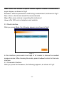
1
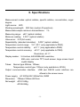
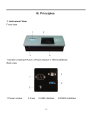
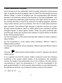
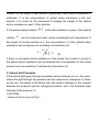
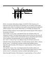
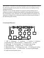
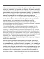
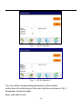
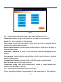
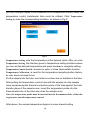
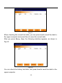
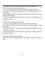
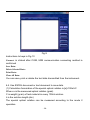
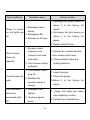
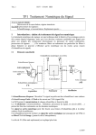
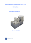
Contents
I. APPLICATIONS................................................................................................... - 1 II. SPECIFICATIONS.............................................................................................. - 2 III. PRINCIPLES...................................................................................................... - 3 IV OPERATION....................................................................................................... - 9 V. MAINTENANCE ............................................................................................... - 21 VI SUPPLEMENT ................................................................................................. - 23 -
Warning: The responsible person must be clear that the protective
function of this instrument can be impaired if the method adopted by the user
during the operation procedure is not the same as that specified by the
manufacturer.
Warning: All kinds of solvents should be placed with care during
analysis procedure in accordance with the lab safety regulations. Refer to
corresponding material safety data sheets whenever you need. Do wear lab
coat, goggles and rubber gloves at any time. Care must be taken to avoid the
possible burns whenever using hot reagents.
Warning: Electric shock.The cover or plate should be removed only by
the qualified personnel.
I. Applications
Polarimeter is the instrument used to measure optical rotation through which
the concentration, content and purity of substances can be analyzed and
determined, thus it finds wide applications in sugar making, medicine,
petroleum, food, chemicals and other industries, as well as universities and
research institutes.
AP-81/85 automatic polarimeter (shortened as “instrument”) adopts LED as
the light source to avoid frequent sodium lamp replacement. The instrument
is equipped with built-in Peltier accurate temperature control system
(available only in AP-85), which has heating and cooling functions. If
temperature control tubes are utilized, the instrument can perform
temperature control measurement towards sample optical rotation.
-1-
II. Specifications
Measurement modes: optical rotation, specific rotation, concentration, sugar
degree
Light source: LED
Working wavelength: 589.3nm (sodium D spectrum)
Measurable sample minimum transmittance: 1%
Measuring range: ±45° (optical rotation)
Minimum reading: 0.001° (optical rotation)
Value error: 0.01(full scale)
Repeatability: (standard deviation): 0.002° (optical rotation)
Temperature control range: 15℃-30℃ (only applicable to P850)
Temperature control stability: ±0.1℃ (only applicable to P850)
Temperature control accuracy: ±0.3℃ (only applicable to P850)
Resolution: ±0.1℃
Display modes: 5.6 inches, 640×RGB×480 resolution,
65K color, real color TFT, touch screen, large screen liquid
crystal display
Tubes: Normal type 200mm, 100mm;
Temperature control type: 100mm (only available in AP-85)
Output communication interface: USB and RS232 serial interface are
offered in the screen menu
Power supply: AC 220V±22V, 50Hz±1Hz, 250W
Dimension: 708mm×330mm×287mm
Net weight: AP-81 24Kg
AP-85 26Kg
-2-
2. Basic Application Principles
As it is known to all, the visible light, which is usually referred to as the natural
light, is actually the electromagnetic wave of which the wavelength is among
380nm~780nm. In terms of statistical law, the corresponding light vibration
spreads in all directions vertical to the direction of the light propagation, and
the corresponding amplitudes (light intensity) of the light vectors are equal. If
the vibration direction is fixed to be vertical to the light propagation direction
using certain devices (such as polarizer), then the so called plane polarized
light is formed. The polarized light changes in vibration direction as it goes
through certain substance, which is called optical active substance and the
changed angular is called optical rotation. When the plane polarized light
goes through certain pure optical active substance, optical rotation is decided
by the following three factors:
(a) The wavelength λ of the plane polarized light, different λ leads to different
optical rotation.
(b) The temperature t of the optical active substance, different t leads to
different optical rotation.
(c) The type of the optical active substance, different type has different optical
rotation.
A
C'
D'
t
t
t
B'
-90°
The term
α+α
'
D
0
α'
B
β β
t
+90
°
α+α'
C
β β
β β
图1
called special optical rotation is used to represent the optical
rotatory power.
It is a general rule that the optical rotation measured under the following
conditions is the special optical rotation of the substance, the conditions
include: the length of the polarimeter tube is 1dm (100mm), the test solution
concentration is 1g/ml, the temperature is t℃ and the wavelength of the
plane polarized light is λ. As the special optical rotation is only determined by
the substance structure, it is a physical constant unique to the material.
α λt = [α ]λ • L • C
t
(1)
-4-
Where L is the length of test solution (polarimeter tube) and is measured in
millimeter; C is the concentration of optical active substance in the test
solution. It is usual for the instrument to display the weight of the optical
active substance in each 100ml solution.
If the special optical rotation [α ]λ of the test substance is given, then optical
t
rotation
α λt can be measured under certain wavelength and temperature; if
the length of the test solution is L, the concentration C of the optical active
substance can be figured out according to formulation (2).
C=
α λt
[α ]λt ⋅ L
(2)
If there is non-optical active substance in the solute, the content or purity of
the optical active substance can be obtained from concentration of the mixed
solution and concentration C obtained by formulation (2).
3. Optical Null Principles
If the natural light goes through a polarizer and an analyzer in turn, the place,
where the light through the polarizer and the analyzer is orthogonal, is taken
as the null. According to the Malus law, the relation between α, the angular
between the analyzer and the orthogonal position, and I, the incidence light
intensity of the analyzer, is
I=I0COS2α
, shown as the curve A in Fig.1
-5-
A
D'
C'
t
t
-90°
α +α'
D
0
B
β β
B'
t
t
+90°
α'
α+α '
C
β β
β β
图1
When a sinusoidal alternating voltage u=Usin2πft of the frequency f is
imposed on the two terminals on the Faraday coil, according to the Ferrari
magnetic-optic effect, the vibration plane shall be superimposed an additional
rotation angular: α1=β·sin2πft. When there is a Faraday coil between the
polarizer and the analyzer, the emergent light intensity signals of the analyzer
are shown as follows:
(a) B and B′ curves in Fig.1 are obtained when the vibration plane is at
orthogonal position. The light intensity signal, which is shown as the curve B′,
is formed by a certain constant light intensity and an alternating light intensity
of the frequency 2f superimposing on the constant light intensity.
(b) C and C’ curves in Fig.1 are obtained when the vibration plane is at
rightward of the orthogonal position. The light intensity signal, which is shown
as the curve C’, is formed by a certain constant light intensity and an
alternating light intensity of the frequency f superimposing on the constant
light intensity.
(c) D and D’ curves in Fig.1 are obtained when the vibration plane is at
leftward of the orthogonal position. The light intensity signal, which is shown
as the curve D’, is formed by a certain constant light intensity and an
alternating light intensity of the frequency f superimposing on the constant
-6-
light intensity. The phase of this alternating light intensity is opposite to that of
the alternating light intensity when the vibration plane is at rightward of the
orthogonal position.
Therefore, we can decide whether the analyzer and the polarizer are at
orthogonal position by determining whether the alternating light intensity of
the f component is zero. Similarly, we can decide whether the analyzer is at
rightward or leftward of the orthogonal position by determining the phase of
the alternating light intensity.
4. Instrument Structure
12
11
10
9
8
7
6
5
19
4
3
2
1
17
13
20
14
22
18
21
16
23
15
1. LED 2. Diaphragm 3. Condenser
4. Polarizer 5. Modulator
6.Collimating lens7. Tube 8. Analyzer 9.Objective lens 10. Filter
11. Diaphragm 12. Photomultplier 13. Automatic high-voltage
14. Pre-amplification 15. Motor control 16. Servo motor
17. Mechanical drive 18. Rotating code count 19. Heating and cooling
10. Temperature control
21. SCM control 22. Liquid crystal display
23. Light source and power source
-7-
Instrument structure is shown in Fig.2. The light sent by the LED in turn goes
through the diaphragm, the condenser, the polarizer, the Faraday modulator
and collimating lens, and finally turns into a collimating plane polarized light
whose vibration plane varies with the alternating voltage of the Faraday coil.
Then the polarized light goes through the test solution tube, the analyzer, the
objective lens, the filter and the diaphragm, and finally turns into a
monochromatic light whose wavelength is 589.3nm. After this, the light goes
into the photomultiplier, which transforms the light intensity signals into the
electrical signals, and is amplified by the pre-amplifier. Automatic
high-voltage automatically changes the photomultiplier high-voltage
according to the incidence light intensity of the photomultiplier as to measure
the brunet samples with low transmittance.
If the analyzer deviates from the orthogonal position compared with the
incidence polarized light plane, the alternating light intensity signal of the
frequency f is able to pass through and then transformed into the electrical
signal of the same frequency by the photomultiplier. After this, the electrical
signal goes through in turn pre-amplifier, motor control, frequency-selecting,
power amplifier and then drives the servo motor to turn the polarizer through
mechanical drive. When the polarized light plane of the polarizer is
orthogonal to the analyzer, the electrical signal of the frequency f disappears
and the servo motor stops.
When the instrument begins to work properly, the polarizer automatically
turns and stops at the orthogonal position (defined as the null) according to
the previous process, then counter is reset. For example, if the tube with the
sample, whose optical rotation is α, is placed into the sample room, and the
incidence plane polarized light derivates α from the orthogonal position, thus
the polarizer repeats the previous process--- turning the polarized light of α
and reaching the orthogonal position. The coded disc counter and SCM
circuit then change α, of which the polarizer turns, into optical rotation and
-8-
display the measurements on the liquid crystal display.
The instrument is equipped with temperature controller, which can control
sample temperature. Temperature control polarimeter tube shall be utilized
when temperature control is needed. The actually measured polarimeter tube
temperature by the platinum resistor is input to the SCM. Then the
temperature value is displayed by the liquid crystal display, meanwhile the
temperature control signal is sent to the temperature control circuit to control
the heating or cooling of the semiconductor cooler, so the temperature of the
polarimeter tube is kept around the setting value. Besides, you can decide
whether the temperature control is needed by pressing the buttons in the
liquid crystal display at any time.
IV Operation
1. Use Conditions
1.1. The instrument should be mounted on the stable workbench to avoid
vibration. At least 10cm must be guaranteed between the instrument and
surrounding walls for prompt heat dissipation.
1.2. The instrument should be kept away from humidity and corrosion of the
corrosive gas to stay dry, and it is best to use the instrument in the 20℃
working environment.
1.3. The instrument power supply should be the alternating current power
supply with 220V, 50Hz (AC electronic voltage stabilizer is useful if the
voltage is unstable). Insert the power plug into the power socket and
guarantee the ground pins are firmly grounded.
2. Operation
2.1. Main Interface
After the instrument starts, wait for a few seconds to see the window form of
the main interface in the screen, as shown in Fig.1:
-9-
Fig. 1(AP-81 interface)
Fig. 1(AP-85 interface)
You can set the corresponding parameters in this window.
Instructions to function keys in the main interface as shown in Fig.1:
Re-measure: measures again
Reset: sets data to zero
- 10 -
Mode: offers four modes of optical rotation, specific rotation, concentration,
sugar degree, as shown in Fig.2
Parameter: sets the parameters used during measurement, as shown in Fig.3.
Data: stores, checks and sends the measurements
Help: offers some notices in operating the instrument
About: offer 400 service telephone and website
2.2. Mode Interface
After you press Mode, the following appears, as shown in Fig.2:
Fig. 2
In this interface, press each icon keys of all modes to choose the needed
measure mode. After choosing the mode, press Confirm to return to the main
interface.
2.3. Parameter Interface
After you press the Parameter, the following appears, as shown in Fig.3
- 11 -
Fig.3
2.3.1. Instructions to function keys in the main interface in Fig.3:
Measurement Times: times of instrument to re-measure automatically
Sample No.: sets numbers for the samples
Tube Length: inputs the tube length, which must be done in special optical
rotation and concentration modes.
Special Optical Rotation: inputs sample optical rotation, which must be done in
concentration mode
Instrument Calibration: is used in the instrument internal debugging before
factory.
Concentration: inputs sample concentration, which must be done in special
optical rotation mode
Communication Method: chooses USB or RS322 serial communication
Date and Time: sets current date and time
Temperature Setting: sets control temperature, opens or closes temperature
control (only available in AP-85)
2.3.2. Instructions to interface functions in Fig.3:
There are setting buttons corresponding to the parameters in this interface.
- 12 -
After touching key, you enter into the parameter digital setting interface. For
example, after you click Measurement Times, the following interface appears,
as shown in Fig.4:
Fig.4
After you press the corresponding digital buttons in this interface, the digit
that needs to be set appears. After you have completed the settings, press
Confirm to go back to the previous interface and then press Back to go back
to the main interface. The parameter setting process such as Sample No.,
Tube Length, Optical Rotation, Concentration, Communication Method as well as
Date and Time are the same with Measurement Times process: click the button
to go to the corresponding interface, press the digit to complete setting, and
return to the main interface successively to carry out measurement.
Among the above settings, the Temperature Setting (only available in A P-81)
and Instrument Calibration are done in the instrument internal debugging
before factory, so there is no need for user to set.
Note: In the special optical rotation mode, Concentration and Tube Length must be
set; in the Concentration mode, Special Optical Rotation and Tube Length must be
set.
- 13 -
(AP-85) If sample needs to be measured in the temperature control mode, the
temperature control polarimeter tube must be utilized. Click Temperature
Setting to enter the corresponding interface, as shown in Fig.5:
Fig.5
Temperature Setting: sets the temperature at the desired value. After you click
Temperature Setting, the interface goes to temperature setting interface where
you can set the desired temperature and press Confirm to complete setting.
Temperature Control Switch: chooses to open or close thermostatic function.
Temperature Calibration: is used for the temperature sampling before factory,
so user does not need to set.
Put the sample into the tube, and make sure there are no bubbles in the tube.
After putting the temperature control tube with the sample into the sample
room and pressing the thermal conductive plane of the tube against the heat
transfer plane of the sample room, insert the temperature probe into the
thermometer hole of the tube and close the sample room.
Note: the temperature probe must be inserted into the thermometer hole of the tube
to guarantee smooth temperature control.
After above, the sample temperature begins to move toward setting
- 14 -
temperature and finally reaches the setting value. After the temperature is
stable, re-measure for several times to ensure the correctness of the
measurements.
Enter into the temperature control interface and click Close Temperature
Control before removing the tube or there is no need to conduct
measurement.
2.4. Digital Interface
After you press Digital Graph, the following interface appears, as shown in
Fig.6:
Fig.6
Press Current Data to check the current test data; press History Data to check
the previous test data.
After you press Current Data, the following interface appears.
- 15 -
Fig.6-1
When checking the current test data, you can press Send to send the data to
the upper computer and press Save to save the current data.
After you press History Data, the following interface appears, as shown in
Fig.6-2
Fig.6-2
You can check the history test data, and press Send to send the data to the
upper computer.
- 16 -
2.5. Help Interface
After you press Help, the interface appears, as shown in Fig.7:
Fig.7
2.6. About Interface
After you press About, the interface appears, as shown in Fig.8:
- 17 -
Fig.8
3. Recommended Operation Process of Sample Measurement
(1) Place the tube with instilled water or blank solvent into the sample room,
close the sample room, and press Reset. Then zero appears on the display. If
there are bubbles in the tube, make them float at raised neck of the tube; if
there are fog water drops at both ends of the smooth surface, wipe up with a
soft cloth. Tube nut should not spin too tightly or the stress would be raised
affecting the reading. Pay attention to the mark, position and direction when
placing the tube.
(2) Remove the tube. Inject the test sample into the tube, place it into the
sample room at the same position and direction, and close the lid. The optical
rotation (or corresponding indicating value) is displayed.
(3) The instrument sets automatic measurement n times, so n readings are
obtained and average value is displayed. If Measurement Times is set one, you
can re-measure manually by pressing Re-measure. If the process shall be
re-measured more than one time, press Re-measure to clear the previous
measurements and measure successively n times.
(4) Press Reset before each measurement.
(5) Disconnect the power after use.
- 18 -
4. Method of Building Communication between Instrument and PC
4.1. Build Communication through Serial Port
(1) Firmly connect the RS232 communication cables before starting up;
(2) Choose the COM communication mode in the parameter setting of the
polarimeter.
(3) Open the “Blue Sea Series” upper computer software in the PC, select
COM and click Connect.
(4) After you press Send during the measuring process, the data appears in
the display interface.
4.2. Build Communication through USB
(1) Firmly connect the USB communication cables before starting up;
(2) Choose the USB communication mode in the parameter setting of the
polarimeter.
(3) Open the “Blue Sea Series” upper computer software in the PC, select
USB and click Connect.
(4) After you press Send during the measuring process, the data appears in
the display interface.
4.3. Upper Computer Communication
The communication software interface of the upper computer is shown in
Fig.9:
- 19 -
Fig.9
Instructions to keys in Fig.10
Connect: is clicked after COM, USB communication connecting method is
confirmed
Save Data:
Delete Selected Data:
Print Data:
Clear All Data:
You can save, print or delete the test data transmitted from the instrument.
4.4. Use EXCEL document or text document to save data.
(1) Calculation formulation of the special optical rotation is [α]=100α/LC
Where α is the measured optical rotation (grad).
C is weight (gram) of test material in every 100ml solution
L is the solution length (dm)
The special optical rotation can be measured according to the mode 2
operation.
- 20 -
(2) Purity of the material can be figured by the measured special optical
rotation:
Purity=actually measured special optical rotation/ theoretical special optical
rotation
(3) Computational rules of measuring international sugar content:
According to the international sugar degree standard, it is manipulated that
the optical rotation of the 100ml solution in the 2dm tube with 26g pure sugar
is +34.626° and its sugar degree is 100°Z measured by sodium light in 20℃.
This instrument adopts mode 4, so the international sugar degree can be
read directly.
V. Maintenance
1. The instrument should be kept away from humidity and corrosion of the
corrosive gas to stay dry, and it is best to use the instrument in the 20℃
working environment.
2. The polarimeter tube should be wiped with soft cloth to keep clean before
placed into the sample room and avoid corrosion of the corrosive gas.
- 21 -
Fault conditions
Possible cause
Actions to take
1. Exchange the power switch or
Power is turned
on, but lights are
off.
1. Damaged power
switch;
2. Damaged LED;
3. Burned-out 2A fuse.
return it to the factory for
repair;
2. Exchange the light source or
return it to the factory for
repair;
3. Replace the 2A fuse.
1. Excess contact
Touch screen
does not
respond
between color
1. Reduce the contact with the
screen touch area
and shell;
color screen touch area;
2. Check whether there are
2. Color screen quality
quality problems.
problems.
1. The encoder cable
Counter does not
work.
plug off;
2. Check the power;
2. Whether the
encoder power is
normal.
The instrument
cannot be
connected with
PC.
1. Insert the plug;
1. Damaged USB
cables;
2. On-line program
errors.
- 22 -
3.Return it to the factory for
repair.
1. Check the cable and make
sure soldering is intact;
2. Contact the manufacturer.
VI Supplement
Since the date of sale (starts from the date of invoice), this product is
guaranteed for one year, but the following conditions are not within the scope
of the warranty:
1. Over warranty period;
2. Instrument damage due to improper use;
3. Instrument damage due to disassemble without manufacturer’s permission
4. Instrument damage due to improper transportation and storage.
- 23 -