1
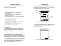
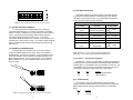
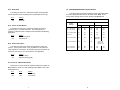
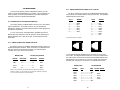
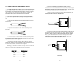
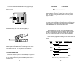
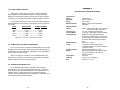
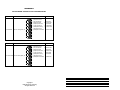
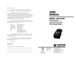
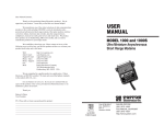
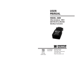
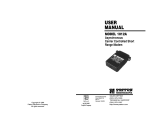
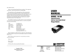
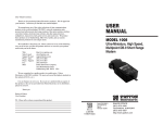
USER
MANUAL
MODEL 2085
High Speed RS-232
to RS-485 Interface
Converter
Part# 07M2085-D
Doc# 047033UD
Revised 4/15/97
CERTIFIED
An ISO-9001
Certified Company
1.1 RADIO AND TV INTERFERENCE
The Model 2085 generates and uses radio frequency energy, and if
not installed and used properly—that is, in strict accordance with the
manufacturer's instructions—may cause interference to radio and
television reception. The Model 2085 has been tested and found to
comply with the limits for a Class A computing device in accordance
with the specifications in Subpart J of Part 15 of FCC rules, which are
designed to provide reasonable protection from such interference in a
commercial installation. However, there is no guarantee that
interference will not occur in a particular installation. If the Model 2085
does cause interference to radio or television reception, which can be
determined by disconnecting the RS-232 interface, the user is
encouraged to try to correct the interference by one or more of the
following measures: moving the computing equipment away from the
receiver, re-orienting the receiving antenna and/or plugging the
receiving equipment into a different AC outlet (such that the computing
equipment and receiver are on different branches).
1.2 CE NOTICE
The CE symbol on your Patton Electronics equipment indicates
that it is in compliance with the Electromagnetic Compatibility (EMC)
directive and the Low Voltage Directive (LVD) of the Union European
(EU). A Certificate of Compliance is available by contacting Technical
Support.
1
2
2.0 GENERAL INFORMATION
Thank you for your purchase of this Patton Electronics product.
This product has been thoroughly inspected and tested and is
warranted for One Year parts and labor.
3.0 CONFIGURATION
The Model 2085 is configured using an eight position DIP switch
and a DCE/DTE switch. Figure 1 (below) shows the location of the
DCE/DTE switch (externally accessible) on the PC board, as well as
the power supply daughter board and terminal block.
DCE/DTE
Switch
2.1 FEATURES
• Operates asynchronously, point to point or multipoint,
over 2 or 4 wires
• Up to 50 multipoint device drops in a polling environment
• Data rates to 115.2 Kbps
• Passes transmit & receive data, one control signal each direction
• No AC power or batteries are required
Terminal
Block
+RCV- G -XMT+
• Variable high/low impedance settings
• Able to operate with or without “echo”
• Carrier can be set as “constantly on” or “controlled by RTS”
Figure 1. Top view of Model 2085 board, showing DCE/DTE switch.
• Compact size ( 2.66” x 2.10” x 0.73”)
• Twisted pair connection via strain relief, RJ-11 or RJ-45
• Silicon Avalanche Diode surge protection
2.2 DESCRIPTION
Figure 2 (below) shows the location of the eight position DIP switch
on the underside of the Model 2085 PC board. Figure 3 (following
page) shows the orientation of the eight position DIP switch, with
respect to ON/OFF positions.
The Model 2085 High Speed RS-232 to RS-485 Interface
Converter provides exceptional versatility in a compact package.
Requiring no AC power or batteries for operation, the Model 2085
supports asynchronous RS-232 data rates to 115.2 Kbps over one or
two unconditioned twisted pair.
The Model 2085 passes one control signal in each direction and
can handle up to 50 terminal drops in a multipoint polling environment.
The Model 2085 may be configured for high or low impedance
operation, carrier may be set to “constantly on” or “controlled by RTS”,
and the unit can operate with or without “echo”. RTS/CTS delay may
be set for “no delay” or 8 mS.
The Model 2085 is equipped with either male or female DB-25 for
RS-232 connection. Options for twisted pair connection include
terminal blocks with strain relief, RJ-11, RJ-45 and DB-25 male or
female. Silicon Avalanche Diodes provide 600 watts per wire of
protection against harmful data line transient surges.
3
DIP Switch
S1
ON
1
2
3
4
5
6
7
8
Figure 2. Bottom view of Model 2085 board, showing (internal) DIP switch.
4
ON
ON
1
2
3
4
5
6
7
8
OFF
3.3 DIP SWITCH SETTINGS
All possible settings for the Model 2085’s configuration switches
are presented in Figure 5 (below). Following Figure 5 is a detailed
description of each switch function. If you have additional questions,
contact Technical Support at (301) 975-1000.
Figure 3. Close-up of DIP switch showing “ON” and “OFF” positions
3.1 SETTING THE DCE/DTE SWITCH
S1 SUMMARY TABLE
Position
Function
S1-1*
“Transmit Off” Impedance
Off
S1-2*
“Transmit Off” Impedance
Off
S1-3
RTS/CTS Delay
On
8 msec
S1-4
“ECHO” Mode
Off
Echo Off
S1-5
Carrier Control
On
RTS Cont.
120 Ohm
For your convenience, the Model 2085 has an externally
accessible DCE/DTE switch. If the device connected to the Model
2085 is a modem or multiplexer (or is wired like one), set the switch to
“DTE”. This setting causes the Model 2085 to behave like Data
Terminal Equipment and transmit data on pin 2. If the device
connected to the Model 2085 is a PC, terminal or host computer (or is
wired like one), set the switch to “DCE”. This setting causes the Model
2085 to behave like Data Communications Equipment and transmit
data on pin 3.
S1-6
Receive Impedance
On
S1-7*
2-Wire/4-Wire
On
S1-8*
2-Wire/4-Wire
On
3.2 DIP SWITCH CONFIGURATION
The eight switches on switch set S1 (see Figure 3, above)
configure the Model 2085 for echo mode, carrier control method,
RTS/CTS delay, “transmit off” impedance, receive impedance, and 2wire/4-wire operation. These switches are located internally on the
Model 2085's PC board. To access switch set S1, use a small flat
blade screwdriver to pop open the Model 2085's case as shown in
Figure 4, below.
Factory Default
}
High Z
}
2-Wire
Figure 5. Summary of DIP switch default settings for set S1
*Note: Switches S1-1 & S1-2 should be switched simultaneously.
Switches S1-7 & S1-8 should also be switched simultaneously.
S1-1 and S1-2: “Transmit Off” Impedance
Switches S1-1 and S1-2 are set together to determine whether the
receiving device “sees” the impedance of the Model 2085’s transmitter
as being “high” or “intermediate” when the transmitter is turned off. The
“intermediate” setting is useful in half-duplex environments where the
receiving device does not respond well to the “high” setting.
S1-1
On
Off
S1-2
On
Off
Setting
Intermediate Impedance
High Impedance
S1-3: RTS/CTS Delay
The setting for switch S1-3 determines the amount of delay
between the time the Model 2085 “sees” RTS and when it sends CTS.
Note: RTS/CTS Delay setting should be based upon transmission
timing.
Figure 4. Opening the Model 2085's plastic case with a small screwdriver
5
S1-3
On
Off
Setting
8 mSec
no delay
6
S1-4: Echo Mode
3.4 CONFIGURATION SWITCH APPLICATIONS
The setting for switch S1-4 determines whether the Model 2085
echoes data back to the transmitting device (half-duplex mode only).
The switch settings generally needed to configure the Model 2085
for various applications are shown in the table below. Note: Do not
change switch settings until you have carefully read Section 3.3.
S1-4
On
Off
Setting
Echo On
Echo Off
TYPICAL MODEL 2085 APPLICATIONS
Point-to-Point
Switch
Settings
S1-5: Carrier Control Method
The setting for switch S1-5 determines whether the carrier is
“Constantly On” or “Controlled by RTS”. This setting allows for
operation in switched carrier, multipoint and/or hardware handshaking
applications.
S1-5
On
Off
Setting
Controlled by RTS
Constantly On
Multi-point
4W
4W HDX
2W
4W
2W
S1-1: “Xmt Off” Imp.
S1-2: “Xmt Off” Imp.
OFF
OFF
OFF
OFF
OFF
OFF
OFF
OFF
OFF
OFF
S1-3: RTS/CTS Delay
ON
ON
ON
OFF
ON
S1-4: Echo
OFF
OFF
OFF
OFF
OFF
S1-5: Carrier Control
OFF
ON
ON
Master-OFF
Slaves-ON
ON
S1-6: Rcv Impedance
ON
ON
ON
S1-7: 2-wire/4-wire
S1-8: 2-wire/4-wire
OFF
OFF
OFF
OFF
ON
ON
S1-6: Receive Impedance
The setting for switch S1-6 selects the impedance of the input
receiver. You may select either a “low” impedance of 120 Ohms or a
“high” impedance of 16 kOhms. By selecting the proper impedance for
each drop, there may be up to 50 receivers in one application.
S1-6
On
Off
Setting
Low (120 Ohm)
High (16 kOhm typical)
S1-7 and S1-8: 2-Wire/4-Wire Modes
Switches S1-7 and S1-8 are set together to determine whether the
Model 2085 is in 2-wire or 4-wire operating mode. Note: 2-wire mode
is half-duplex only.
S1-7
On
Off
S1-8
On
Off
Setting
2-wire mode
4-wire mode
7
8
Master - ON
Slaves - OFF
Last Slave - ON
OFF
OFF
ON
ON
4.0 INSTALLATION
4.1.2 4-WIRE CONNECTION USING RJ-11 OR RJ-45
Once you have properly set the configuration switches, you are
ready to connect the Model 2085 to your system. This section tells you
how to properly connect the Model 2085 to the RS-485 and RS-232
interfaces, and how to operate the Model 2085.
The RJ-11 and RJ-45 connectors on the Model 2085's RS-485 side
are pre-wired for a standard TELCO wiring environment. The signal/pin
relationships are shown below:
RJ-11
SIGNAL
RJ-45
SIGNAL
4.1 CONNECTION TO THE RS-485 INTERFACE
To function properly, the Model 2085 must have one or two twisted
pairs of metallic wire. These pairs must be "dry" (unconditioned)
metallic wire, between 19 and 26 AWG (the higher number gauges may
limit distance somewhat).
For your convenience, the Model 2085 is available with several
different physical interfaces on the RS-485 side: DB-25 (following the
RS-520 standard), RJ-11 jack, RJ-45 jack, and terminal blocks with
strain relief.
1...................GND*
2...................RCV3...................XMT+
4...................XMT5...................RCV+
6...................GND
1 .................N/C
2 .................GND*
3 .................RCV4 .................XMT+
5 .................XMT6 .................RCV+
7 .................GND
8 .................N/C
*Connection to ground is optional
4.1.1 4-WIRE CONNECTION USING THE DB-25
The DB-25 connector on the Model 2085's RS-485 side conforms to
the RS-530 interface standard. When connecting to an RS-485 device
that also conforms to the RS-530 standard, your cable should be
"crossed over" in the manner shown below:
MODEL 2085
SIGNAL
XMT+
XMTRCV+
RCV-
RS-485 (530) DEVICE
DB-25 PIN
DB-25 PIN
2 ...........................3
14 ...........................16
3 ...........................2
16 ...........................14
SIGNAL
RCV+
RCVXMT+
XMT-
In most modular RS-485 applications it is necessary to use a "cross
over" cable. The diagram below shows how a cross over cable should
be constructed for an environment where both the Model 2085 and the
RS-485 device use a 6-wire RJ-11 connector. Similar logic should be
followed when using RJ-45 connectors or a combination of the two.
MODEL 2085
SIGNAL
NOTE: It is not necessary that the RS-485 device adhere to the RS-530
standard. However, you must make sure that the signals, polarities, and pairing
of your connection conform to the above diagram.
9
1
2
3
4
5
6
7
8
1
2
3
4
5
6
GND†
RCVXMT+
XMTRCV+
GND†
RS-485 DEVICE
PIN#
PIN#
1 -------------------N/C
2 -------------------4
3 -------------------5
4 -------------------2
5 -------------------3
6 -------------------N/C
10
RS-422 SIGNAL
XMTRCV+
RCVXMT+
4.1.3 4-WIRE CONNECTION USING TERMINAL BLOCKS
If your RS-485 application requires you to connect two pairs of bare
wires to the Model 2085, you will need to open the case to access the
terminal blocks. The following instructions will tell you how to open the
case, connect the bare wires to the terminal blocks, and fasten the
strain relief collar in place so that the wires won't pull loose.
6. If there is a shield around the telephone cable, it may be
connected to "G" on the terminal block. We recommend connecting the
shield at the computer end only to avoid ground loops. A ground wire is
not necessary for proper operation of the Model 2085.
7. When you finish connecting the wires to the terminal block, the
assembly should resemble the diagram below:
1. You should already have the case open for the configuration
procedure. If not, open the case according to the diagram in Section
3.2.
+RCV- G -XMT+
2. Strip the outer insulation from the twisted pairs about one inch
from the end.
3. Strip back the insulation on each of the 2 twisted pair wires
about .25".
4. Connect one pair of wires to XMT+ and XMT- (transmit positive
and negative) on the terminal block, making careful note of which color
is positive, and which color is negative.
Ultimately, you will want to construct a two pair cross over cable that
makes a connection with the RS-485 device as shown below:
+RCV- G -XMT+
5. Connect the other pair of wires to RCV+ and RCV- (receive
positive and negative) on the terminal block, again making careful note
of which color is positive, and which color is negative.
8. Place the 2 halves of the strain relief assembly on either side of
the telephone wire and press together very lightly. Slide the assembly
so that it is about 2 inches from the terminal posts and press together
firmly. If your cable diameter is too small or too large for our strain
relief, please contact our technical support. We have strain relief
assemblies to accommodate most cable diameters.
RS-485 Device
Model 2085
XMT+.............................RCV+
XMT-..............................RCVRCV+.............................XMT+
RCV-..............................XMT-
11
(continued)
12
9. Insert the strain relief assembly with the wire going through it
into the slot in the bottom half of the modem case and set it into the
recess in the case.
2085 SIGNAL
RS-485 SIGNAL
XMT+ ....................................+
XMT- .....................................The above wiring pattern applies regardless of whether you are
making the RS-485 connection via DB-25, RJ-11, RJ-45 or terminal
blocks. For specific wiring instructions, please refer to the previous
pages of Section 4.
4.2 WIRING FOR MULTIPOINT CIRCUITS
The Model 2085 supports multi-point applications using either a
star or daisy chain topology. Both topologies require special wiring, as
well as specific DIP switch settings for master and slave units. Note:
Refer to Section 3.2.2 for multipoint DIP switch settings.
10. BEND the top half of the case as necessary to place it over the
strain relief assembly. Do not snap the case together yet.
4.2.1 STAR TOPOLOGY
Using a star topology, you may connect several Model 2085s
together in a master/slave arrangement. Maximum distance between
the units will vary based upon the number of drops, data rate, wire
gauge, etc. Call Technical Support for specific distance estimates.
Figure 7 (below) shows how to wire the two-pair cables properly for
a Model 2085 star topology. Note that the ground connection is not
needed.
HOST
XMT+
11. Insert one captive screw through a saddle washer and then
insert the captive screw with the washer on it, through the hole in the
DB-25 end of the case. Snap that side of the case closed. Repeat the
process for the other side. This completes the cable installation
process.
FIRST SLAVE
SECOND SLAVE
RCV+
RCV+
XMT-
RCVRCV-
RCV+
XMT+
XMT+
4.1.4 2-WIRE CONNECTION
RCVMost RS-485 devices employ a two-wire, half duplex configuration.
When using this configuration, be sure to first set the Model 2085 to
"two wire" mode—then use only the transmit (XMT) pair as shown on
the following page.
13
XMTXMT-
Figure 7. Star wiring for Model 2085 host and slaves
14
APPENDIX A
4.2.2 DAISY CHAIN TOPOLOGY
PATTON MODEL 2085 SPECIFICATIONS
Using a daisy chain topology, you may connect several Model
2085s together in a master/slave arrangement. Maximum distance
between the units will vary based upon the number of drops, data rate,
wire gauge, etc. Call Technical Support for specific distance estimates.
Figure 8 (below) shows how to wire the two-pair cables properly for
a Model 2085 daisy chain topology. Note that the ground connection is
not needed.
HOST
FIRST SLAVE
OTHER SLAVE(S)
XMT+---------------------RCV+-----------------------RCV+
XMT- ---------------------RCV- -----------------------RCVRCV+---------------------XMT+-----------------------XMT+
RCV- ---------------------XMT- -----------------------XMT-
Transmission
Format:
Data Rate:
Range:
RS-232 Interface:
RS-485 Interface
Options:
Transmit Line:
Transmit Mode:
Control Signals:
Figure 8. Daisy chain wiring for Model 2085 host and slaves
4.3 CONNECTION TO THE RS-232 INTERFACE
RTS/CTS Delay:
Carrier:
Once you have properly configured the Model 2085 and connected
the twisted pair wires correctly, simply plug the Model 2085 directly into
the DB-25 port of the RS-232 device. Remember to insert and tighten
the two captive connector screws.
Surge Protection:
Power:
(Note: If you must use a cable to connect the Model 2085 to the
RS-232 device, make sure it is a straight through cable of the shortest
possible length—we recommend 6 feet or less).
Temperature:
Humidity:
Size:
Asynchronous
Up to 115,200 bps
Up to 9 miles
DB-25, male or female (DCE/DTE
switchable)
DB-25, male or female; RJ-11 or RJ-45 jack;
terminal block with strain relief
2, 4 wire unconditioned twisted pair
4-wire, full or half duplex; 2-wire half duplex
DSR turns “ON” immediately after the
terminal raises DTR; DCD turns “ON” after
recognizing the receive signal from the line;
CTS turns “ON” after the terminal raises
RTS.
8 mSec or “no delay”
The carrier is switch selected either
continuous operation or switched operation,
controlled by RTS
600W power dissipation at 1 mS
Draws operating power from RS-232 data
and control signals; no AC power or
batteries required.
0 to 50º C
5 to 95%, non-condensing
2.66” x 2.10” x 0.73”
4.4 OPERATING THE MODEL 2085
Once the Model 2085 is properly installed, it should operate
transparently—as if it were a standard cable connection. Operating
power is derived from the RS-232 data and control signals; there is no
“ON/OFF” switch. All data signals from the RS-232 and RS-485
interfaces are passed straight through. Additionally, one hardware flow
control signal is passed in each direction.
15
16
APPENDIX B
PATTON MODEL 2085 RS-232 PIN CONFIGURATIONS
DIRECTION
To Model 2085
“DCE” SETTING
Data Term. Ready (DTR) - 20
DIRECTION
1- (FG) Frame Ground
2- (TD) Transmit Data
3- (RD) Receive Data
4- (RTS) Request to Send
5- (CTS) Clear to Send
6- (DSR) Data Set Ready
7- (SG) Signal Ground
8- (DCD) Data Carrier Detect
“DTE” SETTING
From Model 2085 Data Term. Ready (DTR) - 20
DIRECTION
To Model 2085
From Model 2085
To Model 2085
From Model 2085
From Model 2085
From Model 2085
DIRECTION
1- (FG) Frame Ground
2- (TD) Transmit Data
From Model 2085
3- (RD) Receive Data
To Model 2085
4- (RTS) Request to Send
From Model 2085
5- (CTS) Clear to Send
To Model 2085
6- (DSR) Data Set Ready
To Model 2085
7- (SG) Signal Ground
8- (DCD) Data Carrier Detect To Model 2085
Copyright ©
Patton Electronics Company
All Rights Reserved