1
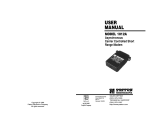
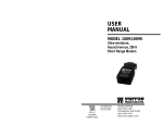
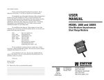
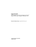
USER
MANUAL
2.1 FEATURES
l
l
l
MODEL 222N
and 222NS
Miniature RS-232 to
RS-422 Converters
l
l
l
l
Bi-directionally converts RS-232 signals to balanced RS-422
DCE/DTE switch selectable on RS-232 interface
Supports transmit and receive data (X-ON/X-OFF flow control)
Loops back all handshaking signals on the RS-232 interface
Very thin case (.75") for closely spaced computer ports
No AC power or batteries required-draws all necessary operating
power from RS-232 interface
Supports data rates to 19.200 bps
2.2 DESCRIPTION
The Patton Model 222N interface converter allows computers,
terminals and modems employing the RS-232E interface to
communicate with devices using RS-422 balanced electrical signals.
This unit derives the necessary power for operation from the data and
control voltages on the RS-232 interface. The 222N features
bi-directional data conversion at full or half duplex at distances up to 3.5
miles.
An external DCE/DTE switch lets you connect to the serial port of
either a computer/terminal (DTE) or a modem (DCE) without using a
crossover cable. The Model 222N is available with several RS-422
interface options: DB-25 male or female (following the RS-530
standard), RJ-11, RJ-45, or terminal blocks with strain relief.
The surge protected Model 222NS uses high speed avalanche
diodes to intercept data line transient surges and shunt them safely to
chassis ground. With surge handling capacity of 600W per wire at
1 mS, the 222NS can protect itself and connected equipment from
nearby lightning strikes, and other surges of electromagnetic radiation.
3.0 CONFIGURATION
4.0 INSTALLATION
The Model 222N is designed to be easy to use. There are no
internal jumpers or DIP switches to set, so there is no need to open the
case to configure the unit (you may need to open the case for wire
connection-refer to section 4.0). The only configuration necessary for
operation is proper setting of the external DTE/DCE switch.
Once you have properly configured the DTE/DCE switch, you are
ready to connect the Model 222N to your system. This section tells you
how to properly connect the Model 222N to the RS-422 and RS-232
interfaces, and how to operate the Model 222N.
The figure below shows the location of the DTE/DCE switch on the
PC board, as well as the location of the terminal block and surge
suppressors (“S” model only).
4.1 CONNECTION TO THE RS-422
DCE/DTE
Switch
L
1
.
1
Surge
Suppressors
(222NS only)
lW/
Terminal
INTERFACE
The Model 222N supports data-only communication distances up
to 4000 feet between itself and the RS-422 device. To function
properly, the Model 222N must have two twisted pairs of metallic wire.
These pairs must be dry, unconditioned metallic wire, between 19 and
26 AWG (the higher number gauges may limit distance somewhat).
For your convenience, the Model 222N is available with several
different physical interfaces on the RS-422 side: DB-25 (following the
RS-530 standard), RJ-11 jack, RJ-45 jack, and terminal blocks with
strain relief.
0
4.1.1 RS-422 CONNECTION USING THE DB-25
3.1 SETTING THE DTE/DCE SWITCH
For your convenience, the Model 222N has an externally
accessible DTE/DCE switch (see diagram below). If the device
connected to the Model 222N is a modem or multiplexer (or is wired like
one), set the switch to “DTE”. This setting causes the Model 222N to
behave like Data Terminal Equipment and transmit data on pin 2.
If the device connected to the Model 222N is a PC, terminal or host
computer (or is wired like one), set the switch to “DCE”. This setting
causes
the Model 222N to behave like Data Communications
_
Equipment and transmit data on pin 3.
The DB-25 connector on the Model 222N’s RS-422 side conforms to
the RS-530 interface standard. When connecting to an RS-422 device
that also conforms to the RS-530 standard, your cable should be
*crossed over’ in the manner shown below:
MODEL 222N
AS-422 (530) DEVICE
SlGNAL
DB-25 PIN
SIGNAL
DB-25 PIN
XMT+
2 ............................ 3
RCV+
XMT14 . . . . . . . . . . . . . . . . . . . . . . . . . . 16
RCVRCV+
RCV-
3 ............................ 2
16 . . . . . . . . . . . . . . . . . . . . . . . . . . 14
XMT+
XMT-
‘The DB-25 connector that is farthest from the DT E/DCE switch
NOTE: It is not necessary that the RS-422 device adhere to the RS-530
standard. However, you must make sure that the signals. polarities. and
pairing of your connection conform to the above diagram.
4.1.2 RS-422 CONNECTION USING RJ-11 OR RJ-45
4.1.3 RS-422 CONNECTION USING TERMINAL BLOCKS
The RJ- 11 and RJ-45 connectors on the Model 222N’s RS-422 side
are pre-wired for a standard ‘TELCO wiring environmenr. The signal/pin
relationships are shown below:
SIGNAL
RJ-11
RJ-45
1 ................... GND’
2 ................... RCV3.. ................. XMT+
4.. ................. XMT5.. ................. RCV+
6.. .................GND
SlGNAL
1 ................. N/C
2 ................. GND’
3 ................. RCV4 ................. XMT+
5 ................. XMT6 ................. RCV+
7 ................. GND
8 ................. N/C
If your RS-422 application requires you to connect two pairs of
bare wires to the Model 222N, you wilt need to open the case to access
the terminal blocks. The following instructions will tell you how to open
the case, connect the bare wires lo the terminal blocks, and fasten the
strain relief collar in place so that the wires won't pull loose.
1. Open the unit by gently inserting a screwdriver between the
DB-25 connector and the lip of the plastic case (see below). You don’t
have to worry about breaking the plastic, but be careful not to bend the
D-sub connector.
In most modular RS-422 applications, it is necessary to use a
"cross over” cable. The diagram below shows how a cross over cable
should be constructed for an environment where both the Model 222N
and the RS-422 device use a 6-wire RJ-11 connector. Similar logic
should be followed when using RJ-45 connectors or a combination of
the two.
MODEL 222N
SIGNAL
PIN
COLOR
GND’
RCVXMT+
XMTRCV+
GND’
1
2
3
4
5
6
RS-422 DEVICE
COLOR PIN# 422 SlGNAL
Blue’ . . . . . . . . . . . . . . . . N/C
Yellow . . . . . . . . . . . . . . Red
Green . . . . . . . . . . . . . . . Black
Red . . . . . . . . . . . . . . . :..Yellow
Black . . . . . . . . . . . . . . . . Green
White . . . . . . . . . . . . . . . N/C
‘Connection to ground is optional
4
5
2
3
XMTRCV+
RCVXMT+
Once the unit has been opened, you will be able to see the
terminal blocks located a! the rear of the PC board.
2. Strip the outer insulation from the twisted pairs about one inch
from the end.
‘Standard AT& T color codes-yours may be different
4.3 OPERATING THE MODEL 222N
3. Strip back the insulation on each of the 2 twisted pair wires
about .25”.
Once the Model 222N is properly installed, it should operate
transparently-as if it were a standard cable connection. Operating
power is derived from the RS-232 data and control signals; there is no
“ON/OFF” switch. All data signals from the RS-232 and RS-422
interfaces are passed straight through. All control signals from the RS232 interface are looped back.
4. Connect one pair of wires to XMT+ and XMT- (transmit positive
and negative) on the terminal block, making careful note Of which color
is positive, and which color is negative.
(Note: If your system requires hardware flow control, you will need the
Patton Model 265 RS-232 to RS-485 converter. Call Patton Customer
Service at 301-975-l 007).
5. Connect the other pair of wires to RCV+ and RCV- (receive
positive and negative) on the terminal block, again making careful note
of which color is positive, and which color is negative.
Ultimately, you will want to construct a two pair cross over cable that
makes a connection with the RS-422 device as shown below:
Model 222N
RS-422 Device
APPENDIX A
SPECIFICATIONS
XMT+ . . . . . . . . . . . . . . . . . . . . . . . . . . . . . RCV+
XMT-- . . . . . . . . . . . . . . . . . . . . . . . . . . . . . .RCVRCV+. ............................ XMT+
RCV-. ............................. XMT6. tf there is a shield around the telephone cable, it may be
connected to ‘G’ on the terminal block. To avoid ground loops, we
recommend connecting the shield at the computer end only. A ground
wire is not necessary for proper operation of the Model 222N.
7. When you finish connecting the wires to the terminal block. the
assembly should resemble the diagram below:
Date Rates: 19,200 bps (according to the RS-232 interface)
Transmlsslon
Format:
Asynchronous
Transmlsslon Mode: Full/half duplex
Power: AC power not required, derives approximately 3mA from
RS-232 data and control voltages
Surge Protection: 600W surge power dissipation at
(1011 OOOuS waveform) and response time of 1 pS
Factory Switch Settlng: DCE; data is received from the remote
short range modem via RX+ and RX-, and is sent to the DTE from
the Model 222N via pin 3 of the RS-232 interface; (the RS-232
interface is the DB-25 connector closest to the DTE/DCE switch)
Dlmenslons: 2.20’ x 1.75’ x .75’
APPENDIX C
BLOCK DIAGRAM
APPENDIX B
RS-232C PIN CONFlGURATlONS
-_
T
DIRECTION 1
STANDARD “DCE” SETTING
DlRECTlON
(FG) Fram Ground
(TD) Transmit Data
(RD) Receive Data
(RTS) Request to send
(CTS) Clear to send
(DSR) Data Set Ready
(SG) Signal Ground
(DCD) Data Carrier Detect
To Model 222N
From Mcdd 222N
To Model 222N
From Model 222N
From Model 222N
From Model 222N
,
DIRECTION
1
STANDARD “DTE” SETTING
-
From Model222 N Data Term. Ready (DTR)
-20
l-(FG)FrameGround
2- (TD) Trasmit Data
3- (RD) Receive Data
4- (RTS) Request to Send
5- (CTS) Clear to Send
6- (DSR) Data Set Ready
7. (SG) Signal Ground
a (DCD) Data Carrier Detect
From Model 222N
To Model 222N
From Modd 222N
To Model 222N
To Model 222N
To Model 222N
3i