1
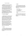
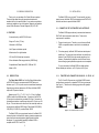
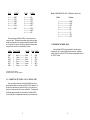
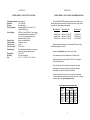
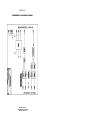
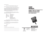
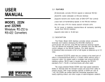
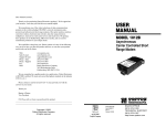
USER
MANUAL
MODEL 1000R and
1000RS
Async. Short Range
Modem for Modular
EIA/TIA-561 Systems
Part #07M1000R-B
Doc. #082011UB
Revised 04/28/98
An ISO-9001
Certified Company
SALES OFFICE
(301) 975-1000
TECHNICAL SUPPORT
(301) 975-1007
http://www.patton.com
1.0 WARRANTY INFORMATION
1.3 SERVICE
Patton Electronics warrants all Model 1000R components to be
free from defects, and will—at our option—repair or replace the product
should it fail within one year from the first date of shipment.
This warranty is limited to defects in workmanship or materials, and
does not cover customer damage, abuse or unauthorized modification.
If this product fails or does not perform as warranted, your sole
recourse shall be repair or replacement as described above. Under no
condition shall Patton Electronics be liable for any damages incurred
by the use of this product. These damages include, but are not limited
to, the following: lost profits, lost savings and incidental or
consequential damages arising from the use of or inability to use this
product. Patton Electronics specifically disclaims all other warranties,
expressed or implied, and the installation or use of this product shall be
deemed an acceptance of these terms by the user.
1.1 RADIO AND TV INTERFERENCE
The Model 1000R generates and uses radio frequency energy, and
if not installed and used properly—that is, in strict accordance with the
manufacturer's instructions—may cause interference to radio and
television reception. The Model 1000R has been tested and found to
comply with the limits for a Class A computing device in accordance
with the specifications in Subpart J of Part 15 of FCC rules, which are
designed to provide reasonable protection from such interference in a
commercial installation. However, there is no guarantee that
interference will not occur in a particular installation. If the Model
1000R does cause interference to radio or television reception, which
can be determined by disconnecting the modem, the user is
encouraged to try to correct the interference by one or more of the
following measures: moving the computing equipment away from the
receiver, re-orienting the receiving antenna and/or plugging the
receiving equipment into a different AC outlet (such that the computing
equipment and receiver are on different branches).
All warranty and nonwarranty repairs must be returned freight
prepaid and insured to Patton Electronics. All returns must have a
Return Materials Authorization number on the outside of the shipping
container. This number may be obtained from Patton Electronics
Technical Service at
telephone: (301) 975-1007,
web address: http://www.patton.com;
email: [email protected].
NOTE: Packages received without an RMA number will not be
accepted.
Patton Electronics’ technical staff is also available to answer any
questions that might arise concerning the installation or use of your
Model 1000R. Technical Service hours: 8AM to 5PM EST, Monday
through Friday.
1.2 CE NOTICE
The CE symbol on your Patton Electronics equipment indicates
that it is in compliance with the Electromagnetic Compatibility (EMC)
directive and the Low Voltage Directive (LVD) of the Union European
(EU). A Certificate of Compliance is available by contacting Patton
Technical Support.
1
2
2.0 GENERAL INFORMATION
Thank you for your purchase of this Patton Electronics product.
This product has been thoroughly inspected and tested and is
warranted for One Year parts and labor. If any questions or problems
arise during installation or use of this product, please do not hesitate to
contact Patton Electronics Technical Support at (301) 975-1007.
3.0 INSTALLATION
The Model 1000R is easy to install. This section tells you how to
properly connect the Model 1000R to the twisted pair and EIA/TIA-561
interfaces, and how to operate the Model 1000R.
3.1 CONNECTION TO THE TWISTED PAIR INTERFACE
2.1 FEATURES
• Connects directly to the EIA/TIA-561 device
• Range to 17 miles (27.2 km)
• Data rates to 19,200 bps
• No AC power or batteries required
• Miniature size fits in tight locations
• RJ-11 and RJ-45 twisted pair connection
• Silicon Avalanche Diode surge protection (1000RS only)
• Compatible with Patton Models 1000, 1009 and 1015
• Made in USA
The Model 1000R supports data-only communication between an
EIA/TIA-561 device and another serial device. There are two
requirements for installation:
1. These units work in pairs. Therefore, you must have one Model
1000R or compatible modem at each end of a two twisted pair
cable.
2. To function properly, the Model 1000R needs two twisted pairs of
metallic wire. The pairs must be unconditioned, dry metallic wire,
between 19 and 26 AWG (the higher number gauges may limit
distance). Standard dial-up telephone circuits or leased circuits
that run through signal equalization equipment are not acceptable.
For your convenience, the Model 1000R is available with two
different twisted pair interfaces: an RJ-11 jack or an RJ-45 jack.
2.2 DESCRIPTION
3.1.1 TWISTED PAIR CONNECTION USING RJ-11 OR RJ-45
The Patton Model 1000R Low-Cost Short Range Modem allows
an EIA/TIA-561 device to communicate with RS-232 devices at
distances up to 17 (27.2 km) miles over two unconditioned twisted pair.
Supporting asynchronous data rates to 19.2 Kbps, the Model 1000R
requires no AC power or batteries.
The RJ-11 and RJ-45 connectors on the Model 1000R's twisted
pair interface are pre-wired for a standard TELCO wiring environment
(see Figure 1). The table on the following page shows the signal/pin
relationships.
Measuring only 2.0” x 1.7” x .8” (5.1 x 4.3 x 2.0 cm), the Model
1000R is housed in an ABS plastic case. Connection to the EIA/TIA561 serial port is achieved using a modular RJ-45 jack. Connection to
the twisted pair interface is made through either an RJ-11 jack or an RJ45 jack. The serial device at the other end of the twisted pair cable can
be connected to the Model 1000R using a Patton Model 1000 (DB-25),
1009 (DB-9), 1015 (DB-15) or another Model 1000R.
The Model 1000S is a surge protected version of the Model 1002
that uses the latest in bi-directional, clamping, transient suppressors to
protect itself and connected equipment against harmful transient
discharges. For surge handling capability, the Model 1000S is
compliant with IEC 801.5 level 2, 1kV.
3
1 - Blue
2 - Orange
3 - Black
4 - Red
5 - Green
6 - Yellow
7 - Brown
8 - Slate
1 - Blue
2 - Yellow
3 - Green
4 - Red
5 - Black
6 - White
Figure 1. AT&T standard modular color codes
4
RJ-1
1
SIGNAL
RJ-45
1 ----------------GND†
2 ----------------RCV3 ----------------XMT+
4 ----------------XMT5 ----------------RCV+
6 ----------------GND†
SIGNAL
Pin No.
1 ----------------N/C
2 ----------------GND†
3 ----------------RCV4 ----------------XMT+
5 ----------------XMT6 ----------------RCV+
7 ----------------GND†
8 ----------------N/C
†
PIN# COLOR‡
GND†
RCVXMT+
XMTRCV+
GND†
1
2
3
4
5
6
COLOR
Blue---------------------White
Yellow ------------------Red
Green ------------------Black
Red ---------------------Yellow
Black -------------------Green
White -------------------Blue
PIN# SIGNAL
6
4
5
2
3
1
Function
1 --------------------------------DSR
2 --------------------------------DCD
3 --------------------------------DTR
4 --------------------------------SG
5 --------------------------------RD
6 --------------------------------TD
7 --------------------------------CTS
8 --------------------------------RTS
When connecting two Model 1000Rs, it is necessary to use a
“crossover” cable. The diagram below shows how a crossover cable
should be constructed for an environment where both Model 1000Rs
use a 4-wire RJ-11 connector. Similar logic should be followed when
using an RJ-45 connector or a combination of the two.
SIGNAL
Model 1000R EIA/TIA-561 8 Position Interface:
GND†
XMTRCV+
RCVXMT+
GND†
3.3 OPERATING THE MODEL 1000R
Once the Model 1000R is properly installed, it should operate
transparently—as if it were a standard cable connection. Operating
power is derived from the EIA/TIA-561 data and control signals; there is
no “ON/OFF” switch.
Connection to ground is optional
Standard color codes—yours may be different
‡
3.2 CONNECTION TO THE EIA/TIA-561 SERIAL PORT
Every serial device connected to the Model 1000R must have a
special interface cable that conforms to the EIA/TIA-561 standard. On
one end, this cable must have a male RJ-45 plug, on the other end, it
must have a connector that fits into your serial device. The diagram on
the following page shows the pin connections for the Model 1000R.
Connect each pin to the appropriate connection on your serial device.
5
6
APPENDIX A
PATTON MODEL 1000R SPECIFICATIONS
Transmission Format:
Data Rate:
Distance:
Surge Protection:
Control Signal:
Transmit Line:
Transmit Mode:
Transmit Level:
Line Connection:
Power Supply:
Temperature:
Humidity:
Size:
Asynchronous
0 to 19,200 bps
See table below
Compliant with IEC 801.5 level 2, 1kV
(Model 1000RS only)
DCD (pin 2) and DSR (pin 1) turn on when
modem is powered up (connected); CTS
(pin 7) turns on immediately after the
terminal raises RTS (pin 8)
4-wire, unconditioned line
Full duplex, 4-wire
0 dBm
RJ-11, RJ-45
No external power required, uses ultra low
power from data and control signals
32° to 140°F
95% non-condensing
2.0” x 1.7” x 0.8” (5.1 x 4.3 x 2.0 cm)
APPENDIX B
PATTON MODEL 1000R CABLE RECOMMENDATIONS
The Patton Model 1000R operates at frequencies of 20kHz or less
and has been performance tested by Patton technicians using twistedpair cable with the following characteristics:
Wire Gauge
19 AWG/.9mm
22 AWG/.6mm
24 AWG/.5mm
Capacitance
Resistance
83nf/mi or 15.72 pf/ft.
83nf/mi or 15.72 pf/ft.
83nf/mi or 15.72 pf/ft.
.0163 Ohms/ft.
.0326 Ohms/ft.
.05165 Ohms/ft.
To gain optimum performance from the Model 1002, please keep
the following guidelines in mind:
• Always use twisted pair wire—this is not an option.
• Use twisted pair wire with a capacitance of 20pf/ft or less.
• Avoid twisted pair wire thinner than 26 AWG (i.e. avoid higher
AWG numbers than 26)
• Use of twisted pair with a resistance greater than the above
specifications may cause a reduction in maximum distance
obtainable. Functionality should not be affected.
• Environmental factors too numerous to mention can affect the
maximum distances obtainable at a particular site. Use “maximum
distance” figures as a general guideline only.
Model 1000 Distance Table in Miles (km)
Data Rate
(bps)
19,200
9,600
4,800
2,400
1,200
7
Wire Gauge
19 AWG
24 AWG
( 0.9 mm) (0.5 mm)
6.2(9.9)
3.7(5.9)
7.5(12.0) 4.9(7.8)
8.7(13.9) 5.6(9.0)
11.8(18.9) 8.0(12.8)
17.0(27.2) 11.8(18.9)
8
26 AWG
(0.4 mm)
1.2(1.9)
2.5(4.0)
3.7(5.9)
4.9(7.8)
8.0(12.8)
APPENDIX B
PATTON MODEL 1000R BLOCK DIAGRAM
Copyright © 1998
Patton Electronics Company
All Rights Reserved