1
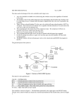
Programming Overview
4 Programming Overview
This chapter explains how to program the MicroLogix 1000 programmable
controller. Read this chapter for basic information about:
principles of machine control
understanding file organization and addressing
understanding how processor files are stored and accessed
Programming
•
•
•
•
•
applying ladder logic to your schematics
a model for developing your program
4–1
MicroLogix
Preface1000 Programmable Controllers User Manual
Principles of Machine Control
The controller consists of a built-in power supply, central processing unit (CPU),
inputs, which you wire to input devices (such as pushbuttons, proximity sensors,
limit switches), and outputs, which you wire to output devices (such as motor
starters, solid-state relays, and indicator lights).
Programming
Device
User Input Devices
User Output Devices
Inputs
Memory
(Programs and Data)
Outputs
CPU
Processor
Power Supply
MicroLogix 1000 Programmable Controller
4–2
CR
Programming Overview
With the logic program entered into the controller, placing the controller in the
Run mode initiates an operating cycle. The controller’s operating cycle consists of a
series of operations performed sequentially and repeatedly, unless altered by your
program logic.
overhead
input
scan
service
comms
program
scan
Programming
Operating Cycle
output
scan
input scan – the time required for the controller to scan and read all input data;
typically accomplished within µseconds.
program scan – the time required for the processor to execute the instructions in the
program. The program scan time varies depending on the instructions used and
each instruction’s status during the scan time.
Note
Subroutine and interrupt instructions within your logic program may cause
deviations in the way the operating cycle is sequenced.
output scan – the time required for the controller to scan and write all output data;
typically accomplished within µseconds.
service communications – the part of the operating cycle in which communication
takes place with other devices, such as an HHP or personal computer.
housekeeping and overhead – time spent on memory management and updating
timers and internal registers.
You enter a logic program into the controller using a programming device. The
logic program is based on your electrical relay print diagrams. It contains
instructions that direct control of your application.
4–3
MicroLogix
Preface1000 Programmable Controllers User Manual
Understanding File Organization
The processor provides control through the use of a program you create, called a
processor file. This file contains other files that break your program down into
more manageable parts.
Processor File Overview
Most of the operations you perform with the programming device involve the
processor file and the two components created with it: program files and data files.
Processor File
Program Files
(14 Maximum)
Data Files
(8 Maximum)
The programming device stores processor files on hard disk (or floppy disk).
Monitoring and editing of processor files is done in the workspace of the computer.
After you select a file from disk and edit it, you then save the file hard to disk,
replacing the original disk version with the edited version. The hard disk is the
recommended location for a processor file.
PROGRAMMING DEVICE
Workspace
01
Hard Disk
01
02
03
04
Uniquely named
processor files
Processor files are created in the offline mode using the programming device.
These files are then restored (downloaded), to the processor for online operation.
4–4
Programming Overview
Program Files
Program files contain controller information, the main ladder program, interrupt
subroutines, and any subroutine programs. These files are:
•
•
•
•
•
•
System Program (file 0) – This file contains various system related
information and user-programmed information such as processor type, I/O
configuration, processor file name, and password.
Reserved (file 1) – This file is reserved.
Main Ladder Program (file 2) – This file contains user-programmed
instructions defining how the controller is to operate.
User Error Fault Routine (file 3) – This file is executed when a recoverable
fault occurs.
High-Speed Counter Interrupt (file 4) – This file is executed when an HSC
interrupt occurs. It can also be used for a subroutine ladder program.
Selectable Timed Interrupt (file 5) – This file is executed when an STI occurs.
It can also be used for a subroutine ladder program.
Subroutine Ladder Program (files 6 – 15) – These are used according to
subroutine instructions residing in the main ladder program file or other
subroutine files.
Data Files
Data files contain the status information associated with external I/O and all other
instructions you use in your main and subroutine ladder program files. In addition,
these files store information concerning processor operation. You can also use the
files to store “recipes” and look-up tables if needed.
These files are organized by the type of data they contain. The data file types are:
•
•
•
•
•
Output (file 0) – This file stores the state of the output terminals for the
controller.
Input (file 1) – This file stores the status of the input terminals for the
controller.
Status (file 2) – This file stores controller operation information. This file is
useful for troubleshooting controller and program operation.
Bit (file 3) – This file is used for internal relay logic storage.
Timer (file 4) – This file stores the timer accumulator and preset values and
status bits.
4–5
Programming
•
MicroLogix
Preface1000 Programmable Controllers User Manual
•
•
•
Counter (file 5) – This file stores the counter accumulator and preset values
and the status bits.
Control (file 6) – This file stores the length, pointer position, and status bits for
specific instructions such as shift registers and sequencers.
Integer (file 7) – This file is used to store numeric values or bit information.
Understanding How Processor Files are Stored and
Accessed
The MicroLogix 1000 programmable controller uses two devices for storing
processor files: RAM and EEPROM. The RAM provides easy access storage
(i.e., its data is lost on a power down), while the EEPROM provides long-term
storage (i.e., its data is not lost on a power down). The diagram below shows how
the memory is allocated in the micro controller’s processor.
RAM
EEPROM
CPU Workspace
Retentive Data
Program Files
Backup Data
Retentive Data
Program Files
CPU
The memory device that is used depends on the operation being performed. This
section describes how memory is stored and accessed during the following
operations:
•
•
•
•
4–6
download
normal operation
power down
power up
Programming Overview
Download
When the processor file is downloaded to the micro controller, it is first stored in the
volatile RAM. It is then transferred to the non-volatile EEPROM, where it is stored
as both backup data and retentive data.
RAM
EEPROM
CPU
Note
Programming Device
If you want to ensure that the backup data is the same for every micro controller you
are using, save the program to disk before downloading it to a micro controller.
Normal Operation
During normal operation, both the micro controller and your programming device
can access the processor files stored in the RAM. Any changes to retentive data that
occur due to program execution or programming commands affect only the retentive
data in the RAM.
The program files are never modified during normal operation. However, both the
CPU and your programming device can read the program files stored in RAM.
EEPROM
RAM
Backup Data
Retentive Data
Program Files
CPU Workspace
Retentive Data
Program Files
CPU
Programming Device
4–7
Programming
CPU Workspace
Retentive Data
Program Files
Backup Data
Retentive Data
Program Files
MicroLogix
Preface1000 Programmable Controllers User Manual
Power Down
When a power down occurs, only the retentive data is transferred from the RAM to
the EEPROM. (The program files do not need to be saved to the EEPROM since
they cannot be modified during normal operation.) If for some reason power is lost
before all of the retentive data is saved to the EEPROM, the retentive data is lost.
This may occur due to an unexpected reset or a hardware problem.
RAM
EEPROM
CPU Workspace
Retentive Data
Program Files
Backup Data
Retentive Data
Program Files
CPU
Programming Device
Power Up
During power up, the micro controller transfers the program files from the
EEPROM to the RAM. The retentive data is also transferred to the RAM, provided
it was not lost on power down, and normal operation begins.
RAM
EEPROM
CPU Workspace
Retentive Data
Program Files
Backup Data
Retentive Data
Program Files
CPU
4–8
Programming Device
Programming Overview
If retentive data was lost on power down, the backup data from the EEPROM is
transferred to the RAM and used as the retentive data. In addition, status file bit
S2:5/8 (retentive data lost) is set and a recoverable major error occurs when going to
run.
RAM
EEPROM
CPU Workspace
Retentive Data
Program Files
CPU
Programming Device
Programming
Backup Data
Retentive Data
Program Files
4–9
MicroLogix
Preface1000 Programmable Controllers User Manual
Addressing Data Files
For the purposes of addressing, each data file type is identified by a letter
(identifier) and a file number.
File
Type
Identifier
File
Number
Output
Input
Status
Bit
Timer
Counter
Control
Integer
O
I
S
B
T
C
R
N
0
1
2
3
4
5
6
7
The addresses are made up of alphanumeric characters separated by delimiters.
Delimiters include the colon, slash, and period.
Specifying Logical Addresses
The format of a logical address, xf:e, corresponds directly to the location in data
storage.
4–10
Where:
Is the:
x
File type: O—output
I—input
S—status
B—binary
T—timer
C—counter
R—control
N—integer
f
File #:
4—timer
5—counter
6—control
7—integer
:
File delimiter: Colon or semicolon delimiter separates file and structure/word numbers.
e
Element number: 0 to: 0—output
1—input
32—status
31—binary
0—output
1—input
2—status
3—binary
39—timer
31—counter
15—control
104—integer
Programming Overview
You assign logical addresses to instructions from the highest level (element) to the
lowest level (bit). Addressing examples are shown in the table below.
To specify the
address of a:
Use these parameters:➀
Word within an integer file
N
7
:
2
File Type
File Number
File Delimiter
Word Number
T 4 : 7 . ACC
File Type
File Number
File Delimiter
Structure Number
Delimiter
Word
Bit within an integer file
N 7 : 2 /
5
File Type
File Number
File Delimiter
Word Number
Bit Delimiter
Bit Number
B 3
Bit within a bit file
/ 31
File Type
File Number
Bit Delimiter
Bit Number
Bit files are bit stream continuous files, and therefore you can
address them in two ways: by word and bit, or by bit alone.
Bit within a structure file
(e.g., a control file)
➀
R 6 : 7
/ DN
File Type
File Number
File Delimiter
Structure Number
Delimiter
Mnemonic
Some programming devices support short addressing. This allows you to eliminate the file number and file
delimiter from addresses. (For example: N7:2=N2, T4:12.ACC=T12.ACC, B3:2/12=B2/12) Consult your
programming device’s user manual for information on addressing capabilities.
4–11
Programming
Word within a structure file
(e.g., a timer file)
MicroLogix
Preface1000 Programmable Controllers User Manual
You can also address at the bit level using mnemonics for timer, counter, or control
data types. The available mnemonics depend on the type of data. See chapters 6
through 13 for more information.
Specifying Indexed Addresses
The indexed address symbol is the # character. Place the # character immediately
before the file-type identifier in a logical address. You can use more than one
indexed address in your ladder program.
Enter the offset value in word 24 of the status file (S:24). All indexed instructions
use the same word S:24 to store the offset value. The processor starts operation at
the base address plus the offset. You can manipulate the offset value in your ladder
logic before each indexed address operation.
When you specify indexed addresses, follow these guidelines:
•
•
•
Make sure the index value (positive or negative) does not cause the indexed
address to exceed the file type boundary.
When an instruction uses more than two indexed addresses, the processor uses
the same index value for each indexed address.
Set the index word to the offset value you want immediately before enabling an
instruction that uses an indexed address.
Instructions with a # sign in an address manipulate the offset value stored at
S:24. Make sure you monitor or load the offset value you want prior to using
an indexed address. Otherwise unpredictable machine operation could occur
with possible damage to equipment and/or injury to personnel.
Example of Indexed Addressing
The following Masked Move (MVM) example uses an indexed address in the
source and destination addresses. If the offset value is 10 (stored in S:24), the
processor manipulates the data stored at the base address plus the offset.
MVM
MASKED MOVE
Source
#N7:10
0
Mask
0033
Dest
4–12
#N7:50
0
Programming Overview
In this example, the processor uses the following addresses:
Value:
Base Address:
Offset Value in S:24
Offset Address:
Source
N7:10
10
N7:20
Destination
N7:50
10
N7:60
Addressing File Instructions – Using the File Indicator (#)
COP
FLL
BSL
BSR
FFL
FFU
Copy File
Fill File
Bit Shift Left
Bit Shift Right
(FIFO Load)
(FIFO Unload)
LFL
LFU
SQO
SQC
SQL
Programming
The file instructions below manipulate data table files. These files are addressed
with the # sign. They store an offset value in word S:24 (index register), just as with
indexed addressing discussed in the last section.
(LIFO Load)
(LIFO Unload)
Sequencer Output
Sequencer Compare
Sequencer Load
If you are using file instructions and also indexed addressing, make sure that
you monitor and/or load the correct offset value prior to using an indexed
address. Otherwise, unpredictable operation could occur, resulting in possible
personal injury and/or damage to equipment.
Numeric Constants
You can enter numeric constants directly into many of the instructions you program.
The range of values for most instructions is –32,768 through +32,767. These values
can be displayed or entered in several radixes. The radixes that can be displayed
are:
•
•
•
•
Integer
Binary
ASCII
Hexadecimal
4–13
MicroLogix
Preface1000 Programmable Controllers User Manual
Program Development
Process
Design
Functional Specification
Perform
Detailed Analysis
Determine if Special
Programming
Features are Needed
Create Logic
Program
Confirm I/O
Addresses
Enter/Edit
Program
Check for
Completeness
Monitor/Troubleshoot
Program
Accept
Program
Run program.
4–16
Program Development
Checklist
❏ Prepare a general description of how you want your
automated process to operate.
❏ Identify the hardware requirements.
❏ Match inputs and outputs with actions of the process.
❏ Add these actions to the functional specifications.
❏
❏
❏
❏
Do you need:
Special interrupt routines?
High-speed counting features?
Sequencing Operations?
FIFO or LIFO stack operations?
❏ Use worksheets if necessary to create program.
❏ Make sure I/O addresses match correct input and
output devices.
❏ Enter program using the programming device.
❏ Review your functional specification and detailed
analysis for missing or incomplete information.
❏ Monitor and, if necessary, troubleshoot the
program that you entered.
❏ Resulting programs should match functional
specifications.