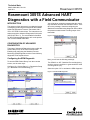
1
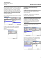
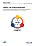
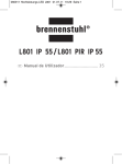
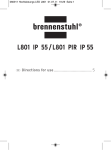
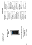
Technical Note
00840-1000-4801, Rev AA
April 2011
Rosemount 3051S
Rosemount 3051S Advanced HART
Diagnostics with a Field Communicator
INTRODUCTION
The purpose of this document is to explain the basics
of configuring and using the Rosemount 3051S HART
Advanced Diagnostics Pressure Transmitter with a
375 or 475 Field Communicator. The instructions are
written around the Advanced Diagnostics DA2 option
(3051S HDT Rev. 3). For more detailed information
on 3051S Advanced Diagnostics, refer to the product
user’s manual 00809-0100-4801.
You will be given a warning message that the control
loop should be removed from automatic control. Click
OK on the message. Note that configuring the
Statistical Process Monitoring diagnostic will not affect
the pressure measurement or analog output of the
transmitter.
Figure 2. Warning Message
CONFIGURATION OF ADVANCED
DIAGNOSTICS
The setup of Advanced Diagnostics is done within the
Guided Setup menu of the Field Communicator.
Enabling and configuring the Statistical Process
Monitoring (SPM) diagnostic and the Power Advisory
diagnostic will be explained here.
Configuring the SPM Diagnostic
To start the SPM Guided Setup, from the overview
screen, use the menu keys:
Configure (2) > Guided Setup (1) > Diagnostics Setup
(2) > Statistical Process Monitoring (1)
Figure 1. Starting SPM Guided Setup
www.rosemount.com
Next, you will see the following message:
Turn SPM On or Off? Statistical Process Monitoring
monitors process conditions to generate HART alerts
or analog alarms (On).
Select the option “On” to activate the SPM diagnostic.
Figure 3. Activate SPM Diagnostic
Technical Note
Rosemount 3051S
Next, you will be asked what SPM variable you want
to use for the detection. For most diagnostics
applications, it is recommended to use “Stdev &
Mean.” For plugged impulse line detection in varying
DP flow applications, it is recommended that you
select the option “Coefficient of Variation.”
00840-1000-4801, Rev AA
April 2011
Next, select the detection threshold (alert sensitivity)
for Standard Deviation. You can start with a medium
threshold, although, this can be adjusted later.
Figure 6. Selecting Detection Threshold for Standard
Deviation
Figure 4. Setting Up SPM Variable
Next, you will need to enter the sample window time
for the SPM. This is the length of time over which the
statistical values (e.g. mean and standard deviation)
are calculated. A longer sample window will give a
more stable and consistent value for standard
deviation, but it will also take longer for the SPM to
respond to an abnormal condition. A shorter window
may make the diagnostic more prone to false
detections. For many diagnostics applications, you
can accept the default of 3 minutes.
Set the Detection Action (Alert or Alarm) for a
standard deviation change. For most applications,
the detection action should be set to Alert. Use “Alert
Unlatched” if the HART alerts will be regularly
monitored by the host system (e.g. AMS Alert
Monitor). Use “Alert Latched” if the host system is
likely to miss alerts due to slow HART polling rates.
Figure 7. Setting Detection Action for Standard Deviation
Change
Figure 5. Entering Sample Window Time
Alternatively, the detection action can be set to
“Alarm.” This will cause the device to go into the
Alarm state (e.g. driving the current to 3.5 mA or 23
mA) if the SPM diagnostic detects an abnormal
condition. This option could be used for legacy host
systems which cannot read digital HART alerts.
However, note that the host system will not be able to
determine which device alert has occurred. For
example, both a failure in the pressure sensor and an
SPM detection may cause the device to drive to
alarm. The user will need to use a Field
Communicator to determine the cause of the device
alarm.
2
Technical Note
00840-1000-4801, Rev AA
April 2011
Next, select both a Sensitivity Level and an Action for
a Mean Change detection. It is recommended that
the detection action be set to “Relearn” because if
the process conditions (e.g. flow rate) change, this
could also cause a change in the process dynamics
(standard deviation). To avoid this causing a false
detection, the SPM should learn the new process
dynamics characteristics.
Figure 8. Selecting Sensitivity Level and Action for a Mean
Change Direction
Rosemount 3051S
Configuring the Power Advisory
Diagnostic
Configuration of the Power Advisory diagnostic can
also be done within the Guided Setup menu. Use the
menu keys to enable and configure the Power
Advisory diagnostic:
Configure (2) > Guided Setup (1) > Diagnostics
Setup (2) > Power Advisory (2)
IMPORTANT:
During the Loop Characterization the current output
of the pressure transmitter will momentarily drive to 4
mA and 20 mA. Ensure that all operational
procedures (e.g. placing control loop in manual
mode) are followed before beginning the Loop
Characterization.
Click OK to proceed with the Power Advisory
configuration.
Finally, click OK at the message “Loop may be
returned to automatic control” to complete the
method.
Figure 10. Power Advisory Configuration
Figure 9. Completing SPM Setup
Select “Yes” to perform the Loop Characterization.
While the Characterization is in progress, you will
see an hour glass icon on the screen.
Figure 11. Performing Loop Characterization
3
Technical Note
00840-1000-4801, Rev AA
April 2011
Rosemount 3051S
After the Loop Characterization you will be shown the
allowable range for the Voltage Deviation Limit, and
then be asked to enter a value. You can accept the
default of 1.5 V.
Figure 12. Entering Value for the Voltage Deviation Limit
ACCESSING THE ADVANCED
DIAGNOSTICS INFORMATION
The following explains how to use the 375 or 475
Field Communicator to look at the details of an
abnormal event detected by the 3051S Advanced
Diagnostics after an alert or alarm is seen in the host
system.
Checking the Device Status
Finally, set the Detection Action for the Power
Advisory Diagnostic. The options are “Alert Latched,”
“Alert Unlatched,” and “Alarm.” In this example, we
select “Alert Latched,” Click OK to complete the
method.
Figure 13. Setting the Detection Action for the Power
Advisory Diagnostic
After the Advanced Diagnostics capabilities have
been configured, the diagnostic algorithms will
operate continuously. If a diagnostic event (e.g. SPM
High or Low variation or Power Advisory) is detected,
then either a digital HART alert will be generated or
the loop current will drive to the High or Low alarm
value, depending upon which detection mode was
configured. After connecting the Field
Communicator, you will see a message indicating the
alert that was detected. The Field Communicator
continuously polls for device alerts, and whenever a
device alert is present, this message will appear.
Click “Yes” to ignore the next 50 occurrences of the
alert and continue using the Communicator. This
message will continue to show up periodically until
the device alert condition is cleared.
Figure 14. Device Alert
4
Technical Note
00840-1000-4801, Rev AA
April 2011
Rosemount 3051S
Viewing the SPM Status and Variables
Shortcuts (3) > SPM Status (2) > Trends (4)
If an SPM Alert was detected the following steps can
be used to view the trend of the SPM data and adjust
the detection settings if necessary.
Figure 17. Viewing a Trend of an SPM Variable
The current device status and alerts can be seen by
navigating to:
Overview (1) > Status (1) > Device Status (1).
Figure 15. Locating Device Status
On the trends list, select the SPM variable that you
want to view. Note that the Field Communicator
does not have any process data storage capability.
Once you open up the trend window, it will begin
drawing the trend from the current point in time. You
will see the trends for the baseline statistical value,
current statistical value, and upper and lower limits.
Select the device alert (e.g. High Variation Detected)
and then select “Alert Description” to view the
detailed information. For “High Variation Detected”
the description includes a list of possible abnormal
conditions that could cause this event.
To highlight a specific trend, select that trend from
the drop-down menu.
Figure 18. Highlighting a Specific Trend
Figure 16. Viewing Alert Description
Viewing a Trend of Statistical Variable
The following explains how to view a trend of an SPM
Variable within a Field Communicator. Navigate to:
5
Technical Note
Rosemount 3051S
00840-1000-4801, Rev AA
April 2011
Setting New Sensitivity for SPM
Viewing the Power Advisory Status
To set new detection limits for the statistical process
monitoring diagnostic, navigate to:
If the Power Advisory condition is active in the
device, after connecting the Field Communicator, you
will see a message indicating the “Power Advisory
Diagnostic.” Click “Yes” to ignore the next 50
occurrences of this diagnostics alert and continue
using the Field Communicator. This message will
continue to show up periodically until the device alert
condition is cleared.
Configure (2) > Alert Setup (3) > Statistical Process
Monitoring (1) > Detection Configuration (3) >
Standard Deviation Detection Settings (1)
Figure 19. Setting New Detection Limits for the Statistical
Process Monitoring Diagnostic
Figure 21. Power Advisory Diagnostics Alert.
To see the current device status, use the menu
sequence:
Overview (1) > Status (1) > Device Status (1)
Figure 22. Getting Current Device Status
Then, select the option “Configure Sensitivity” and
set a new sensitivity value as desired.
Figure 20. Setting New Sensitivity Value
On the Device Status screen the current active alerts
are listed.
To see the detailed information associated with this
detection, select
Power Advisory Diagnostic (2) > Alert Description (1)
6
Technical Note
00840-1000-4801, Rev AA
April 2011
Rosemount 3051S
Figure 23. Viewing Alert Description
The alert description for Power Advisory Diagnostic
will give a list of various conditions that could cause it
to trip.
Figure 24. Alert Description
If the detection mode is set to either “Alert Latched”
or “Alarm.” after the condition that caused the alarm
has cleared, you need to do a “Reset” to clear the
alarm from the device. Note that after a Power
Advisory detection, if the loop characteristics were
changed as part of the remediation (e.g. new power
supply or change wiring), it is necessary to repeat the
Loop Characterization.
Figure 25. Resetting Alarm
7
Technical Note
00840-1000-4801, Rev AA
April 2011
Rosemount 3051S
Standard Terms and Conditions of Sale can be found at www.rosemount.com/terms_of_sale
The Emerson logo is a trade mark and service mark of Emerson Electric Co.
Rosemount and the Rosemount logotype are registered trademarks of Rosemount Inc.
PlantWeb is a registered trademark of one of the Emerson Process Management group of companies.
All other marks are the property of their respective owners.
© 2011 Rosemount Inc. All rights reserved.
Emerson Process Management
Rosemount Measurement
8200 Market Boulevard
Chanhassen MN 55317 USA
Tel (USA) 1 800 999 9307
Tel (International) +1 952 906 8888
Fax +1 952 949 7001
00840-1000-4801 Rev AA, 4/11
Emerson Process Management
Blegistrasse 23
P.O. Box 1046
CH 6341 Baar
Switzerland
Tel +41 (0) 41 768 6111
Fax +41 (0) 41 768 6300
Emerson FZE
P.O. Box 17033
Jebel Ali Free Zone
Dubai UAE
Tel +971 4 811 8100
Fax +971 4 886 5465
Emerson Process Management Asia Pacific
Pte Ltd
1 Pandan Crescent
Singapore 128461
Tel +65 6777 8211
Fax +65 6777 0947
Service Support Hotline : +65 6770 8711
Email : [email protected]