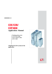
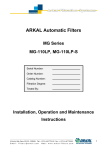
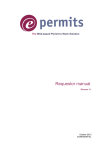
1
AMIAD Water Systems AMC UCP-D Single Model Multi unit Filtration system Control Panel & HMI Serial number: Order number: Catalog number: Filtration degree: Tested by: Operation Instructions Ref.910101-000661 5.2014 Multi AMC UCP-D 5.2014 Page 1 of 34 AMIAD Water Systems AMC UCP-D Single Model Multi unit Filtration system Control Panel & HMI Amiad’s AMC UCP-D Control and HMI system controls the operation of a filtration battery consists of multiple units of single Amiad's filter model, e.g. battery of 4 EBS filters, battery of 10 SAF filters, etc. The system is highly configurable and it is capable of controlling batteries of Amiad filters while providing the user with a multi-lingual Human Machine Interface (HMI). This document describes the software controlling the AMC UCP-D Single Model Multi unit system. The actual number of filter units controlled by this control panel and HMI depends on the hardware capacity of the actual control board and PLC I/Os of each installed project, as depicted in the electrical drawings appendix provided with this document. The AMC UCP-D HMI system contains three major components; Electrical Cabinet, PLC, and HMI display screen. This document describes these components and provides complete set of operation instruction. Disclaimer: This document and the information enclosed within it contain restricted and/or privileged information that are intended only for usage by authorized Amiad technicians. If you are not a qualified Amiad technician, you must not take any action in reliance to this document, unless permitted by Amiad. None of the procedures provided on this file may be used in any form or by any means without permission from Amiad. If you received this file in error, please notify Amiad immediately ([email protected]). The confidential nature of and/or privilege in the file enclosed is not waived or lost as a result of a mistake or error in this file. Amiad accepts no liability whatsoever, whether it was caused by: 1. Accessing or other related actions to this file 2. Any links, procedures, or materials provided/attached to this file Amiad assumes that all users understand risks involved within this file and/or its attached materials. All the procedures, drawings, pictures and/or any other information provided in this document are presented as general information only; they can be altered, removed, or changed without any further notice by Amiad. This document does not replace any certified drawing, procedure, or information provided by Amiad in reference to a specific customer, site, or project. All rights reserved. Multi AMC UCP-D 5.2014 Page 2 of 34 TABLE OF CONTENTS 1. Safety instructions ............................................................................................................. 4 2. Control cabinet drawing ..................................................................................................... 7 3. Control system description ................................................................................................ 8 4. Commissioning, Start-up and first operation ...................................................................12 5. HMI operation ..................................................................................................................16 With any inquiry, please quote Filter Serial Number, located on the filter housing. Multi AMC UCP-D 5.2014 Page 3 of 34 1. SAFETY INSTRUCTIONS 1.1. General Safety Instructions Amiad filtration products always operate as components in a larger system. It is essential for the system designers, installers, and operators to comply with all the relevant safety standards. Prior to installation, operation, maintenance or any other type of action carried out on the filter, read carefully the safety, installation and operation instructions. During installation, operation or maintenance of the filter all conventional safety instructions should be observed in order to avoid danger to the workers, the public or to property in the vicinity. Please note: The filter enters into a flushing mode automatically, without warning. No change or modification to the equipment is permitted without a written notification given in advance by the manufacturer or by its representative, on the manufacturer’s behalf. Always observe standard safety instructions and good engineering practices whilst working in the filter’s vicinity. Use the filter only for its intended use as designed by Amiad, any misuse of the filter may lead to undesired damage and may affect your warranty coverage. Please consult with Amiad prior to any non-regular use of this equipment. 1.2. Installation General Install the filter according to the detailed Installation Instructions provided with the filter by the manufacturer and according to the description given in this manual. Make sure to leave enough clearance to enable easy access for future treatments and safe maintenance operations. The user should arrange suitable lighting at the area of the filter to enable good visibility and safe maintenance. The user should arrange suitable platforms, ladders, and safety barriers to enable easy and safe access to the filter without climbing on pipes and other equipment. The user should verify that any platform, barrier, ladder, or other such equipment is built, installed, and used in accordance with the relevant local authorized standards. Check and re-tighten all bolts during commissioning and after the first week of operation. Use only appropriate standard tools and equipment operated by qualified operators when installing, operating, and maintaining the filter. When installation is required in hazardous environment sites, underground or high above ground, make sure that the site design and the auxiliary equipment are appropriate and that installation procedures are carried out in accordance with the relevant standards and regulations. Ensure walking areas about the installation are slip free when wet. Shipment and transporting Shipping and transporting the filter must be done in a safe and stable manner and in accordance with the relevant standards and regulations. For shipping, lifting and positioning the filter, use only approved lifting equipment and authorized employees and contractors. Electricity Electric wiring should be performed by an authorized electrician only, using standardized and approved components. Install a lockable main power cut-off switch close to the control panel. If due to site constraints, the control panel is installed without a clear line-of sight of the filter, an additional lockable power disconnect cut-off switch should be installed near each filter unit. Installation of the filter should be performed to avoid direct water splashing on the electrical components or on the control panel. Multi AMC UCP-D 5.2014 Page 4 of 34 Pneumatics Install a lockable main cut-off switch, featured with a pressure release mechanism, on the compressed air supply line close to the control panel. If the control panel is installed far away and there is no eye contact with the filter, a lockable compressed air cut-off switch, featured with a pressure release mechanism, should be installed near each filter unit. The user should make sure that the compressed air supplied to the filter never exceeds the maximum designated pressure for this filter. An air-pressure reduction valve should be installed on the compressed air supply line upstream of the filter’s pneumatic inlet port. Hydraulics Extra safety devices should be installed on hot water applications to avoid skin burn danger. The user should install a manual Water Cut-off Valve next to the filter’s inlet port. In cases where the downstream piping network downstream of the filter is pressurized an additional manual Water Cut-off Valve should be installed next to the filter outlet port. The user should make sure that the system includes a Pressure Release / Drainage Valve to enable release of residual pressure prior to any maintenance procedure performed on the filter. The user should make sure that the filter is never exposed to water pressure exceeding the maximum designated pressure for this filter, if needed a Pressure Reduction Valve should be installed upstream of the filter’s water inlet port. Please note that the maximum working pressure indicated at the filter’s specifications table includes the pressure caused by fluid hammer and pressure surge effects. Civil Engineering Make sure that the filter installation is done by qualified by Amiad technicians. Make sure that any civil engineering work at the installation site such as construction, lifting, welding, etc. is done by qualified workers / technicians / contractors and in accordance with the relevant local standards. While using lifting equipment, make sure that the filter or the lifted part is chained securely and in a safe manner. Do not leave lifted equipment if there is no necessity. Avoid working below lifted equipment. Wear a safety helmet while using lifting equipment. Make sure that the flooring is sloped for providing drainage and avoiding accumulation of liquids. 1.3. Commissioning Read carefully the Commissioning and the First Start-up Operation instructions prior to any attempt to operate the filter. In order to achieve maximum performance and smooth operation of the filter it is crucial to perform the Startup and First Operation procedures exactly as described in this manual. Commissioning the filter should be done by an authorized Amiad technician, do not attempt to commission the filter unaccompanied since this may lead to undesired damage and may affect your warranty coverage. 1.4. Operation and Control Do not operate the filter before reading carefully and being familiar with its operation instructions. Observe the safety stickers on the filter and never perform any operation contradicting the instructions given. Never operate or use the filter for purposes other than its original design and operational envelope. Multi AMC UCP-D 5.2014 Page 5 of 34 1.5. Maintenance Before any maintenance or non-regular operation please read the following: Servicing the filter should be done only by technicians authorized by Amiad. Disconnect the filter from the power supply and lock the Main Power Switch. Disconnect the compressed air supply, release the residual pressure, and lock the Pneumatics Main Valve. Disconnect the filter from the water system by closing and securing the Manual Inlet Valve. In cases where the downstream piping network is pressurized, close and secure the Manual Outlet Valve. Release the residual water pressure by opening the Pressure Release / Drainage Valve. Empty the filter by opening the Drainage Valve. In hot water, systems wait until the filter components cool off to a safe temperature. Place warning signs around the work area as required by the local standards and procedures. Inspect the filter’s safety stickers and replace any damaged or faded sticker. Mechanical When working on the filter use only appropriate standard tools. Always open and close valves slowly and gradually. Remove grease and fat material residues in order to avoid slipping. Before disconnecting the filter from the water supply, electricity and pneumatics and before releasing the filter’s residual pressure do NOT: o loosen or unscrew bolts o remove any protection cover o open any service port flange Avoid splashing and water leakage to minimize slippage, electrification, or damage to the equipment, caused by moisture. While using lifting equipment, make sure that the filter or the lifted part is chained securely and in a safe manner. Do not leave lifted equipment if there is no necessity. Avoid working below lifted equipment. Wear a safety helmet, goggles, gloves, and any other personal safety equipment required by the local standards and regulations. Human entry into a filter must be done in accordance with the relevant local safety instructions, standards, and regulations for working in hazardous environment. Manual cleaning of filter media using high water pressure or steam should be performed in accordance with the cleaning system instructions, the local standards and regulations and without endangering the operator or the vicinity Manual cleaning of filter element using acid or other chemical agents should be performed in accordance with the relevant material safety instructions, the local standards, and regulations and without endangering the operator or his vicinity. Before returning to regular operation Re-assemble any protection covers or protection mechanisms removed during service or maintenance operations. Make sure that all the tools, ladders, lifting devices, etc. used during the maintenance procedures are taken away from the filter area and stored In order to return the filter to regular operation, follow the First Start-up Operation instructions as detailed in your user manual. For filters used in potable water systems it is required to disinfect the filter according to the local water authority standards and regulations before putting it back to service. Multi AMC UCP-D 5.2014 Page 6 of 34 2. CONTROL CABINET DRAWINGS See the complete control cabinet drawings in Annex A. provided with this document Multi AMC UCP-D 5.2014 Page 7 of 34 3. CONTROL SYSTEM DESCRIPTION 3.1. General: Amiad’s AMC UCP-D Control and HMI system is highly configurable control system capable of controlling batteries of various models of Amiad filters while providing the user with a multi-lingual Human Machine Interface (HMI). The AMC UCP-D HMI system contains three major components; Electrical Cabinet, PLC, and HMI display screen. This document describes these components and provides complete set of operation instruction. Important note: This document describes the operation of a battery containing multiple units of single Amiad's filter model. Since the number of filters in the battery varies according to the actual number of filter units installed, this document refers to the number of filters as Filter #1 - Filter #N. 3.2. Electrical Cabinet Components: Components mounted on the control panel door In order to provide the end-user with an easy to master user interface, several control elements are mounted on the outside of the control panel enclosure: Switches: MAIN SWITCH – used to switch On/OFF the main power supply Lamps: POWER ON lamp – indicates the status of the Power Supply FAULT red signal lamp - lights on when the system is in Fault Mode Display panels: PLC DISPLAY PANEL – used to read various status data and enter set points Multi AMC UCP-D 5.2014 Page 8 of 34 Internal components of the control panel The rest of the control panel components that are not related to the user interface are mounted inside the controlpanel’s enclosure according to the IP65 standard. An access to these components is allowed only to qualified electricians / technicians who are familiar with this product. It general the internal components of the control panel include elements such as: Power supply elements, PLC unit and extension components, Fuses, Circuit breakers, Over loads, Relays and Solenoids and other similar control elements as depicted in the provided control cabinet drawings. 3.3. PLC Operation: Input / Output List: Inputs: System Inputs (Normally Open): PDS - Digital Differential Switch RS - Remote Start / used also in explosion proof enclosure PF - Pause flushing RF - Reset faults / used also in explosion proof enclosure WM - Water Meter (digital pulse) / used also in explosion proof enclosure Single Filter Inputs (Normally Close): The number of the following components depends on the actual filter units of the filtration system battery. OL - Overload Motor Protector TLS - Top Limit Switch BLS - Bottom Limit Switch Outputs: System Outputs: Selectable output (dry contact and/or 24VDC) for Cycle ON /Downstream Valve/End Of Cycle/System OK (set to OUT#0) Selectable output (dry contact and/or 24VDC) for Cycle ON /Downstream Valve/End Of Cycle/System OK (set to OUT#1) Fault Pilot Alarm Output Filters Outputs: The number of the following components depends on the actual filter units of the filtration system battery. Motor Up (Contra Clockwise - CCW contactor) Motor Down (Clockwise - CW contactor) Flush Valve - Solenoid 24V DC Multi AMC UCP-D 5.2014 Page 9 of 34 3.4. Cleaning Cycle Description The AMC UCP-D HMI system is capable of controlling batteries of various Amiad filter models that comprise one of the following cleaning mechanism types: Brush or Suction Scanner. Very important note: This paragraph contains a general description of the filters operation. For formal details, please refer to your filter user manual. Brush Type filters: During the cleaning cycle of Brush Type filters, the flush valve of the first filter of the battery opens and the motor revolves two stainless steel brushes on the inside of the filtration cylinder. The particles trapped on the cylinder are dislodged by the revolving brushes and flushed out through the open flush valve. Once the cleaning of the first filter is finished, the next filter of the battery is cleaned in the same manner and so on until the last filter (Filter #N) is cleaned. Suction Scanner filters: For models with suction scanner cleaning mechanism, there are two modes of operations: SAF/OMEGA operation mode - During a cleaning cycle, the suction scanner moves in one direction only, i.e. in one cycle it moves from the bottom limit switch (B.L.S) to the top limit switch (T.L.S) and in the next cycle in moves from the T.L.S. to the B.L.S. Once the cleaning of the first filter is finished, the next filter of the battery is cleaned in the same manner and so on until the last filter (Filter #N) is cleaned. EBS operation mode - During a cleaning cycle, the suction scanner moves from the bottom limit switch (B.L.S) to the top limit switch (T.L.S) and then returns to the starting point by moving from the T.L.S. to the B.L.S. Once the cleaning of the first filter is finished, the next filter of the battery is cleaned in the same manner and so on until the last filter (Filter #N) is cleaned. Description of the self-cleaning triggers: Trigger 1: - PDS operation There are three types of DP triggers (depends on system configuration): Digital DP switch, Analog DPT, and calculated DP. The differential pressure is constantly monitored by the configured DP trigger; when the trigger senses a pressure differential higher than, or equal to, the pre-set value (usually 0.5 bar = 7 PSI) a delay of three (3) seconds is counted. If by the end of the delay the signal still exists, a self-cleaning cycle starts. Trigger 2: - Timer operation A self-cleaning cycle according to time intervals is available through a built in timer function in the PLC program. It is possible for the user to set the interval time value for this type of self-cleaning process. The time interval cycles are done regardless of the pressure differential signals; it is recommended to set the timer between 6-8 hours. Whenever another trigger starts a cleaning cycle (such as a PD or a manual start signals) the time interval timer is reset and the time to next flush is counted again. Trigger 3: - "Manual Start" operation The "START" button on the HMI screen is pressed in order to allow a manual self-cleaning cycle to begin. Trigger 4: - REMOTE START operation: A remote start input in the control board terminal is designated to be used as a trigger for starting a remote flushing cycle of the system. Multi AMC UCP-D 5.2014 Page 10 of 34 3.5. The HMI Screen In order to operate the filtration system it is important for the user to be familiar with the operation method of the PLC keyboard and display as described in this chapter. Operation the PLC is done via the keyboard and the display of the KP300 unit. While operating the unit it is important to be aware of the following general issues: Unintentional actions: Unwanted actions may be triggered if the operator unintentionally actuates several keys at once. Never press more than two keys simultaneously. Keyboard damage: Operation of the keys with hard, pointed or sharp objects, or hard impact, may lead to a considerable reduction of the service life and even to complete failure. Always use your fingers to operate the keys of your HMI device. Using the keyboard: The general operation of the keyboard is described in the following table: Function Action Left & Right Arrow Keys Up & Down Arrow Keys Activates the next field in horizontal direction Activates the next field in Vertical direction 1. Undo – you can undo your input as long as you have not yet confirmed it with the Enter key 2. Cancel the output of info-text to return to the previous view 1. Call editing mode – initiates input with the up & down keys 2. Exit editor mode and confirm input N.A. Opens a help screen – if configured N.A. Deletes an entry when in Edit mode ESC Key Enter Key ACK Key Help Key Tab Key Del Key For complete description of the HMI screens see HMI operation chapter Multi AMC UCP-D 5.2014 Page 11 of 34 4. COMMISSIONING, START-UP AND FIRST OPERATION 4.1. Filter's overload calibration process Since the AMC UCP-D HMI system operates a battery of different Amiad filter models, it is absolutely important to calibrate the motor protection (the Overload) of each filter in the battery, and adjust it to the actual motor to be operated. The following is a description of the calibrating procedure of a single overload unit. This procedure should be performed on the motors of all the system's filters. Overload Calibration: 4.1.1. This procedure must be done only by a qualified electrician only and under all relevant local and international safety instructions. 4.1.2. Locate the overload at the upper left side of the control cabinet [A] and open its transparent cover [B]. A B Multi AMC UCP-D 5.2014 Page 12 of 34 4.1.3. Press [A] the RESET button [B] of the Overload device until its power led [C] starts blinking. C B A 4.1.4. Using a screwdriver turn the adjusting screw [A] of the overload right or left and look at the 3 led lams of the overload device (Err, L, R) [B]. These lamps display a binary code that represents the amperage settings of the device. Adjust the required amperage of your specific filter motor as depicted in the following table. A B Multi AMC UCP-D 5.2014 Page 13 of 34 380VAC - 50/60 Hz Power 0.18KW 0.25KW 0.37KW 0.55KW 0.75KW 1.00KW Max. Current 0.45A 0.62A 0.90A 1.37A 1.90A 2.40A Binary Code ERR L 0 1 1 0 1 1 0 0 1 0 1 1 PWR 0 0 0 1 1 1 R 1 0 0 1 0 1 mA 560 710 1020 1480 1940 2400 R 0 1 1 0 0 0 mA 410 560 870 1330 1630 2250 R 0 1 0 0 1 1 mA 410 560 710 1020 1480 2090 440VAC - 50/60 Hz Power 0.18KW 0.25KW 0.37KW 0.55KW 0.75KW 1.00KW Max. Current 0.38A 0.54A 0.80A 1.18A 1.60A 2.20A Binary Code ERR L 0 1 0 1 1 0 0 0 0 1 1 1 PWR 0 0 0 1 1 1 480VAC - 50/60 Hz Power 0.18KW 0.25KW 0.37KW 0.55KW 0.75KW 1.00KW Max. Current 0.35A 0.50A 0.70A 1.00A 1.48A 1.97A Binary Code ERR L 0 1 0 1 1 0 1 1 0 0 1 0 PWR 0 0 0 0 1 1 4.1.5. Once the desired amperage is set, re-press the Rest button [A] and close the overload cover [B]. B A Multi AMC UCP-D 5.2014 Page 14 of 34 4.2. Startup process - filter & panel Very important note: This paragraph contains a general description of the filters operation. For formal details, please refer to your filters user manuals. 1. Before starting-up the filtration-system, read the safety instruction chapter of this document, and pay special attention to the commissioning safety instructions. 2. Inspect the installation of the battery and the filters; make sure that everything is installed in accordance with the official installation drawings. 3. Verify (by authorized electrician only) that the electric wiring is correct and complies with the enclosed drawings. Make sure that an authorized electrician does the electrical start-up operation only. 4. One by one, follow the startup procedure of your filters as appears in your filters formal user manual. 5. Follow the startup procedure of the filtration battery as a whole. 6. Set the flush time interval to 6-8 hours. 7. Check and re-tighten all bolts after the first week of operation. Multi AMC UCP-D 5.2014 Page 15 of 34 5. HMI OPERATION 5.1. General: When power is first connected to the system the main HMI screen appears: The HMI is divided to 5 main menu sections: Home, Status, Process, Logs, and Setup. Accessing each such menu is done by pressing its designated F(x) key, which is located at the keyboard right below the menu name. For the Home screen press F1 For the status menu press F2 For the Process menu press F3 For the Logs menu press F4 For the Setup menu press F5 5.2. Operation conventions: Return to the main system screen by pressing the F1 key When in a menu move along its screens and fields by the UP and DOWN arrow keys Editable data items or user operation fields appear enclosed in a framework while information only data is not framed. Screens with help instructions display the word (HELP) on screen. Press the HELP key to show the help screen and press the HELP key again to exit the help screen. Changing values in editable fields is done by moving to the field using the arrow keys and pressing ENTER for entering to edit mode. Once in edit mode use the arrow keys to scroll through the options with the UP/DOWN keys or enter numbers using the F(x) keyboard keys. Press ENTER to save the new value to the PLC memory. Important notes: When first placing the cursor on an editable field, the field background appears in black (not in edit mode). After pressing the ENTER key the background changes to white. Editing the data can be done only when the background is white. When pressing the ENTER key again the new value is stored; the background terns black and only then it is possible to move to the other fields. To abort editing press the ESC key; the background turns black and moving to other fields is possible The following tables depict all the system screens divided to the 5 menus: Multi AMC UCP-D 5.2014 Page 16 of 34 5.3. The Home screen: When power is applied to the system or when the F1 key is pressed, the main screen appears on the KP300 unit. Main screen Displays the system time and date and the filter type (Omega) Enables entering the 5 sections of the controller’s software Press F1 for Home screen (this screen) Press F2 for Status screens Press F3 for Process screens Press F4 For Logs screens Press F5 For Setup screen Press HELP for the following help screens Important note: When the enclosure is defined as an explosion proof type the letters EX.P appear under the filter type name - see Setup Screen #6 for details. First HELP screen Press the DOWN key to move to the next HELP screen. Press HELP again to exit Second HELP screen Press the UP key to move to the previous HELP screen. Press HELP again to exit Multi AMC UCP-D 5.2014 Page 17 of 34 Main screen at Fault Status When faults exist, the time and date line of the main screen stops displaying the time and instead starts displaying the relevant fault message and the number of the faulty filter. The screen background and the fault lamp start flashing in red. If more than one fault exists, the fault line alternates every 3 seconds, each time displaying different fault message. Move to the system status and the logs menus for more details about the existing faults. 5.4. The Status Menu: (The engineering units in the following screen pictures are metric; the user may switch to US engineering units during the setup process of the system) The screens of this menu appear when the F2 key is pressed. The screens appear in descending order. System Status screen #1 System Status – displays the current system status the options are: Filtering, Flushing, Pause, and Fault. Time to flush – displays the time left until the beginning of the next scheduled flushing cycle in minutes Pressure - displays the current reading of the inlet and the outlet pressure (when such meters are connected to the system). Present D.P. – displays the current D.P. reading (when an analog DP or inlet/outlet meters are connected to the system). Flow rate - displays the current system flow-rate (when water meter is connected to the system). System Status screen #2 Last flush started by: – displays the trigger that started the previous flush cycle: Time, DP, Test. Time between last two flush cycles – displays the time passed since the end of the previous flush cycle and the cycle that preceded it. Water accumulation - displays the total volume of water that passed through the system. Press ENTER on the RESET icon for setting this counter to zero. Flushing left at continuous flushing mode!! - When the system is in continuous flushing mode this line displays the number of flush cycles left until the end of this mode. Note: See setup chapter for continuous flushing mode during emergency flushing. Multi AMC UCP-D 5.2014 Page 18 of 34 System Status screen #3 Time from last flush – displays the time passes from the previous flushing cycle. System Status screen #4 Filters Status This screen displays at its bottom line a status icon per each one of the system filters. Empty square = Filtering Empty circle = Flushing Black circle = Fault Black square = Disabled Please note - This screen picture is of a five filters filtration system, the number of icons presented depends on the battery's actual number of filters. Multi AMC UCP-D 5.2014 Page 19 of 34 5.5. The Process Menu: The screens of this menu appear when the F3 key is pressed. The screens appear in descending order. Manual operation screen (#1) Press ENTER to reset system faults: – Press ENTER on the RESET icon to clear system faults. Press ENTER to start a flush cycle: – Press ENTER on the START icon to start a manual flush cycle. Manual operation screen (#2) Continuous flush - manual mode: – Press ENTER on the START icon to switch the system to continuous flushing mode. Flushing left at continuous flushing mode!! - When the system is in continuous flushing mode this line displays the number of flush cycles left until the end of this mode. Flush Program screen Interval time for flushing - defines the time between scheduled flushing cycles; entering 0 (zero) in this field cancels the "flushing according to time interval" and the "time to next flush" will always show 0 (Zero). DP Set point for flushing - defines the set point for starting the flush process due to DP signal. Maximum allowed value is 0.8 bar / 11.6 psi. Flush time per filter - This line appears only when the system operates ABF filter(s); defines the set point for the flush process time (the time the ABF brushes revolve). Downstream valve delay - This line appears only when a downstream valve is configured at the system; defines the time it takes the valve to complete its closing process. Multi AMC UCP-D 5.2014 Page 20 of 34 6.6. The Logs Menu: The screens of this menu appear when the F4 key is pressed. The screens appear in descending order. Logs screens menu This screen is a menu that enable entry to the following log screens: Flush Counters log - Press F6 Alarm log - Press F7 Flush History log - Press F8 Analog Trends - Press F9 or F10 (there are two trend screens) Flush Counters Log Flush by DP - displays the number of flush cycles that started due to a DP signal. Press ENTER on the RESET icon in order to set this counter to zero. Flush by time - displays the number of flush cycles that started due to time interval. Press ENTER on the RESET icon in order to set this counter to zero. Flush by test - displays the number of flush cycles that started due to a manual start command. Press ENTER on the RESET icon in order to set this counter to zero. Total Flush - displays the total number of flush cycles. Press ENTER on the RESET icon in order to set all the counters to zero. Please note that flush cycles performed when the system is in continuous flush mode are counted in the total flush counter only. Alarm Log This screen presents the existing system alarms. Each line represents a single alarm and displays the alarm details, status, time tag and the number of the faulty filter. Press the (HELP) key for instructions Press the ACK key to acknowledge an alarm See the Alarm List table at the end of this chapter Multi AMC UCP-D 5.2014 Page 21 of 34 The Logs Menu (page 2) 1st Alarm Log Help screen This screen is the first Alarm Log Help screen. It presents the user with general instruction for operating the alarm log screen. 2nd Alarm Log Help screen This screen is the second Alarm Log Help screen. It presents the user with general instruction for operating the alarm log screen. Flush History Log This screen presents a log of the system flush cycles. Each line represents and details a single flush cycle; flush time and date, tag and the trigger started the cycle. Press F1 key to exit Multi AMC UCP-D 5.2014 Page 22 of 34 The Logs Menu (page 3) Trends Screen Downstream pressure (When analog input 2 is configures as a downstream pressure meter) Press the (HELP) key for instructions This screen presents the downstream pressure trend. Press F10 - to start/stop the logging. Press F9 - to extend the trend view. Press F8 - to compress the trend view. Press F7 - to scroll the trend view forward. Press F6 - to scroll the trend view backward. Press F1 - to exit. Trends Help screen This screen is the Trends Help screen. It presents the user with general instruction for operating the trend screen. Trends Screen DP pressure (When analog input 2 is configures as DPT meter) Press the (HELP) key for instructions This screen presents the downstream pressure trend. Press F10 - to start/stop the logging. Press F9 - to extend the trend view. Press F8 - to compress the trend view. Press F7 - to scroll the trend view forward. Press F6 - to scroll the trend view backward. Press F1 - to exit. Trends Screen Upstream pressure Press the (HELP) key for instructions This screen presents the upstream pressure trend. Press F10 - to start/stop the logging. Press F9 - to extend the trend view. Press F8 - to compress the trend view. Press F7 - to scroll the trend view forward. Press F6 - to scroll the trend view backward. Press F1 - to exit. Multi AMC UCP-D 5.2014 Page 23 of 34 5.7. The Setup Menu: The screens of this menu appear when the F5 key is pressed. The screens appear in descending order. In order to change settings an Administrator Password is required. The password is AMDP (F2 F6 F3 F7). The password locked automatically after 10 minutes of operation Setup Screen #1 Press the (HELP) key for instructions on filter type selection Filter type - press ENTER on the filter name field in order to enter to filter type selection mode (see the next line of this table for explanation). Restore factory defaults - Press ENTER on the RESTORE field to reset the controller to its factory defaults settings. Select Language - Press ENTER on the Language field in order to enter to the language selection mode. Setup Screen #1 - Filter type selection Move to the Filter field and press ENTER. Select the required filter type by using the up/down arrow keys. Press ENTER and then move to the OK field Press ENTER again to complete the filter type selection Important Note: This control system is capable of controlling filtration batteries where all the battery's filters are of the same model. Setup Screen #1 - Filter type selection Four Very Important Notes: 1. This message appears for 3 seconds when changing the filter type. It is absolutely important to calibrate the overloads of all the filters in the system according to the type of motor of the selected filter. See chapter 5.1 for instructions. 2. When ABF filter is configured, a signal received from any one of the limit switched immediately causes a limit switch(s) fault. 3. It is very important to perform a "return to factory defaults" operation, immediately after the filter type is changed. 4. After loading software to the PLC it is mandatory to perform "Reset faults" operation in order to clear the flashing red screens. Multi AMC UCP-D 5.2014 Page 24 of 34 The Setup Menu (page 2) Setup screen #1 - 1st Help screens This screen is the first Help screen of the setup screen number 1. It presents the user with general instruction for operating the screen. Setup screen #1 - 2nd Help screens This screen is the second Help screen of the setup screen number 1. It presents the user with general instruction for operating the screen. Setup screen #1 - 3rdt Help screens This screen is the third Help screen of the setup screen number 1. It presents the user with general instruction for operating the screen. Multi AMC UCP-D 5.2014 Page 25 of 34 The Setup Menu (page 3) Setup Screen #2 Number of filters in the system - press ENTER on the number of filters field and enter the number of filter units in the system. Number of filters flushing in parallel - Press ENTER on the number of filters field and enter the number of filters that flush together when the system enters to flushing mode. Engineering units DP and Pressure - Press ENTER on the unit's field in order to enter to select the engineering units for the DP and the Pressure meters (bar, psi, kpa). Setup Screen #3 Engineering units water flow - Press ENTER on the units field in order to enter to select the engineering units for system's water meter (M³/hr, gpm). Volume per pulse - Press ENTER on the volume field and enter the volume of water that passes through the water meter per each pulse sent to the controller. DP Fault - Press ENTER on the selection field in order to enter to the DP fault selection. In Active mode, the filtration stops on general fault when the DP signal is on for more than 10 minutes. When in Ignored mode, the filtration continues and the system does not respond to DP fault with the exception of the emergency flush mode. Motor run delay (help): - use this parameter in case the flush valve opening process is slow. Delay the motor start until the flush valve is fully opened. Important Note - Use the above parameter also to ensure complete closure of the previous filter's flush valve, prior to the motor operation of the currently flushing filter (same as a "Delay between Filters" parameter). Setup Screen #3 first Help screen This screen is the first Help screen of the setup screen #3. It presents the user with general instruction for performing this process. Multi AMC UCP-D 5.2014 Page 26 of 34 The Setup Menu (page 4) Setup Screen #3 second Help screen This screen is the second Help screen of the setup screen #3. It presents the user with general instruction for performing this process. Setup Screen #3 third Help screen This screen is the third Help screen of the setup screen #3. It presents the user with general instruction for performing this process. Setup Screen #4 Press ENTER to change filters status- press ENTER on this icon and select the number of the required filter, then select the required filter mode (enabled or disabled). See the HELP screen. The bottom line of the screen shows the system filters. Black square = Disabled filter Empty square = Enabled filter Please note: the number of icons displayed on this screen depends on the number of filters in the actual filtration battery. Multi AMC UCP-D 5.2014 Page 27 of 34 The Setup Menu (page 5) Setup Screen #4 Help screen This screen is the Help screen of the setup screen #4. It presents the user with general instruction for performing this process. Setup Screen #5 Inlet sensor h.range (20mA) - Press ENTER on the range field and enter the maximum range of the inlet pressure analog meter. Outlet/DPT sensor h.range (20mA) - Press ENTER on the range field and enter the maximum range of the outlet pressure or the differential pressure analog meters. Note: Since these analog meters are of 4-20 type, the software assumes that pressure of ø bar is equal to 4 milliamps, so the user has to enter only the maximum pressure value for the 20milliamp reading. D.P. type - Press ENTER on the selection field and select the type of the DP connected to the system. The options are Digital, Analog DPT, or Calculated (inlet pressure minus outlet pressure). Multi AMC UCP-D 5.2014 Page 28 of 34 The Setup Menu (page 6) Setup Screen #6 Num. of short cycles for cont. mode - enter the number of shorter than 5 minutes flush cycles after which the system enters to continuous flushing mode. Max. Continuous flushing - enter the maximum number of flush cycles to be performed when in continuous flushing mode. Max Emergency flushing - enter the maximum number of flush cycles to be performed when the system is in emergency flushing mode. The system can enter to Emergency flushing only when a downstream valve is configured and when the DP signal is on for more than 30 seconds. In this mode, the filter performs 3 flush cycles with the downstream valve closed. At the end of the emergency flushing, the system opens the downstream valve and performs additional flush cycles as configured in the "number of flush cycles in continuous flushing mode. The system enters to general fault when three emergency flush procedures are carried out in less than 5 minutes delay between them. Enclosure type - Press ENTER on the selection field and select the type of the control board enclosure, standard, or Explosion proof. In EXP. Mode Input 03 is used for connecting a reset button on the external door and input 01 is used for scrolling through the home and the system status displays. In explosion-proof mode, an EXP message appears on the main screen under the filter type headline. Note - In Explosion-proof enclosure, the HMI display is mounted behind a window and the operator has no access to the display buttons. This special feature enables the operator to scroll over the main status screens by pressing special push buttons mounted on the exterior cabinet door. Setup Screen #6 first Help screen This screen is the first Help screen of the setup screen #6. It presents the user with general instruction for performing this process. Multi AMC UCP-D 5.2014 Page 29 of 34 The Setup Menu (page 7) Setup Screen #6 Second Help screen This screen is the second Help screen of the setup screen #6. It presents the user with general instruction for performing this process. Setup Screen #7 Output 0 task - Press ENTER on the selection field and select the task required for the output #0. The options are: Cycle ON / Downstream Valve/ End Of Cycle / System OK Output 1 task - Press ENTER on the selection field and select the task required for the output #1. The options are: Cycle ON / Downstream Valve / End Of Cycle / System OK Note: For outputs 1 & 2 the control board contains in parallel a dry contact and a 24DC contact for these outputs. Downstream valve mode - select the type of operation for the downstream valve (when configured). The options are "When flushing" - the valve closes at the beginning of each flush cycle, "On emergency" the valve closes only during emergency flush at a DP fault status. Note: During continuous flush, the downstream valve remains close in filtration systems configured to flush all their filters in parallel. Setup Screen #7 Help screen This screen is the Help screen of the setup screen #7. It presents the user with general instruction for performing this process. Multi AMC UCP-D 5.2014 Page 30 of 34 The Setup Menu (page 8) Setup Screen #8 This screen enables the user to test the flushing process of a single filter within the system. Enter Filter Num - Press ENTER on the number field and enter the number of the required filter to be tested. Press ENTER to start the flushing process of this filter. Setup Screen #9 This screen enables the user to test the outputs of a single filter within the system. Press Enter to check outputs - Press ENTER on this icon and enable the output check process. Filter number - enter the filter number whose outputs are to be checked. See the HELP screen. Outputs - move to the desired output to be checked. Press and hold the ENTER key to switch this output on. Release the ENTER key to switch this output off. Notes: Downstream valve output - appears only when such valve is configured in the system. (Only a single downstream valve can be configured for the battery) In ABF Filters - Only the "motor up" field appears Setup Screen #9 Help screen This screen is the Help screen of the setup screen #9. It presents the user with general instruction for performing this process. Multi AMC UCP-D 5.2014 Page 31 of 34 The Setup Menu (page 9) Setup Screen #10 This screen enables the user to see the system's inputs status. Empty square represents a disconnected input while black square represents connected input. See the HELP screen. System inputs (the system inputs are Normally Open inputs) DP = Digital DP, RS = Remote start, PF = Pause flushing WM = Water Meter Filter inputs (the filter inputs are Normally Close inputs) Select filter - enter the number of the filter whose inputs are to be checked. OL = Overload, TLS = Top Limit Switch, BLS = Bottom Limit Switch Setup Screen #10 first Help screen This screen is the first Help screen of the setup screen #10. It presents the user with general instruction for performing this process. Setup Screen #10 second Help screen This screen is the second Help screen of the setup screen #10. It presents the user with general instruction for performing this process. Multi AMC UCP-D 5.2014 Page 32 of 34 The Setup Menu (page 10) Setup Screen #11 This screen enables the user to set the real time date and time of the system. Set Time - enter the required values to the Hour, Minute, Month, Day and Year fields and press ENTER on the UPDATE field. The bottom line of this screen displays the software version of the HMI and the PLC together with the number of filters configured in this system. Multi AMC UCP-D 5.2014 Page 33 of 34 5.8. Fault Messages List: ID # 0 1 2 3 4 41 42 43 44 45 46 47 48 Message Text No Fault Filter1 - Direction Fault Filter1 - Limit switch(s) fault Filter1 - Motor fault Filter1 - Overload fault Manual continuous Filtering Analog Input #1 fault 49 50 51 52 Flush by D.P. Flush by time interval Manual flush Filter1 - Disable Analog Input #2 fault No Active filter found Continuous alarm Emergency Flush DP Fault !! Remarks The rotation of filter # 1 drive unit is in the wrong direction. Faulty connection of the filter's limit switches No limit switch signal received at the end of the motor movement The power supply to the filter was disconnected by its Overload Device The filter is in continuous flushing due to a manual start command The filter is in filtering mode The reading of Analog Meter #1 is either lower than 4mA or higher than 20mA. The reading of Analog Meter #2 is either lower than 4mA or higher than 20mA. All the filters in the system are either in Fault or in Disabled mode The filter is in continuous flushing due to short flush cycles The filter is in continuous flushing due to emergency DP signal The DP signal remains high longer than its maximum allowable set point. The system is in fault. The filter flushing started by a D.P. signal The filter flushing started by a time interval signal The filter flushing started by a manual start command The filter operation was disabled by the user Fault messages of filter #2 to Filter #N repeat in the same order as for filter #1 5.9. Data Logger: The AMC UCP-D HMI system includes a built-in data logger. Connect t TCP/IP cable from a laptop computer to the LAN connector of the PLC. Start an IE browser and in the URL line enter the address 192.168.0.2 the system should show the Siemens screen. Navigate to the Data logs option and see the data logged by the PLC. It is possible to download the data to your PC. The data logger loges new records: Every 5 minutes At the beginning of each flush cycle When new fault is registered in the system Please note that during general fault the data logger ceases operation. Multi AMC UCP-D 5.2014 Page 34 of 34