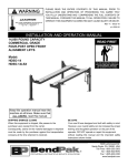
1
Challenger Lifts, Inc.
MODELS 15000 & 18000
TWO POST SURFACE MOUNTED LIFT
OPERATION, INSTALLATION & MAINTENANCE
MANUAL
IMPORTANT
READ THIS MANUAL COMPLETELY BEFORE INSTALLING OR
OPERATING THE LIFT
200 CABEL STREET, P.O. BOX 3944
LOUISVILLE, KENTUCKY 40201-3944
OFFICE (502) 625-0700
FAX (502) 587-1933
Models 15000 & 18000
Installation, Operation and Maintenance
General Specifications
Maximum Capacity* (Model 15000) .............. 15000 US Pounds (3750 Pounds Per Arm)
Maximum Capacity* (Model 18000) .............. 18000 US Pounds (4500 Pounds Per Arm)
Lifting Time**......................................................................Approximately 1 1/2 Minutes
Lowering Time** .....................................................................Approximately 60 Seconds
Motor ....................................................................... 2HP, 230 Volts, Single Phase, 60 Hz.
Optional-2HP, 208 or 240 or 480 Volt, 3 Phase, 50/60 Hz.
Dimensions
Overall Width ...............................................................................................154 3/4 Inches
Overall Height........................................................................ 174 Inches (15000 & 18000)
198 Inches (15002 & 18002)
Height at Full Rise ..........................................................................................85 1/2 Inches
Overhead Clearance............................................................... 167 Inches (15000 & 18000)
191 Inches (15002 & 18002)
Drive Through Clearance..............................................................................106 3/4 Inches
Pick-Up Pad Height ............................................................... 6 1/4 Inches to 16 1/2 Inches
* Lift capacity ratings are based on loads equally distributed on all four arms.
** Lifting and lowering speeds may vary depending on the type and viscosity of the oil in the system and the
temperature of the oil.
COMPONENT PACKING LIST
15000
PART #
18000
12001 12001-18
12002 12002-18
12004
12005
12006
12102
12022
12074
12045
12019
12100
12069
12068
12071
12093
12119 12087-19
12089 12089-19
12090
P/N 12091
#/LIFT
1
1
1
1
1
2
1
1
2
4
2
2
4
1
1
DESCRIPTION
POWER COLUMN ASSY
IDLER COLUMN ASSY
OVERHEAD PACK
HARDWARE BOX
ARM PACK
COLUMN EXTENSION (14'-6" O.A. Ht.)
COLUMN EXTENSION (16'-6" O.A. Ht.)
OVERHEAD SHUTOFF BAR ASSY
MERCURY SWITCH
SYNCHRONIZER CABLE ASSY (16'-6" O.A. Ht.)
SYNCHRONIZER CABLE ASSY (14'-6" O.A. Ht.)
ADAPTER EXTENSION (4")
ADAPTER EXTENSION (8")
ADAPTER RACK
ARM RESTRAINT ASSEMBLY
POWER UNIT - SINGLE PHASE
POWER UNIT - THREE PHASE
LITERATURE PACK
2
Rev. 3/03
Models 15000 & 18000
Installation, Operation and Maintenance
Important!
Before You Install
1. Before installing your Challenger 2-Post lift, read the manual(s) thoroughly. Inspect the lift
to insure that it is complete and undamaged. Challenger 2-Post lifts are shipped ready to
assemble to facilitate shipping and reduce damage. If it is apparent that the lift has been
mishandled in shipment, or if parts or assemblies are missing, note the damage or missing
part(s) on the shipping papers and notify Challenger Lifts, Inc. Immediately.
2. Be certain that the wiring in your building will handle the current required to operate this unit
(Fig 8).
3. Be certain that you have the proper concrete floor to handle the loaded lift. The floor should
be in generally good condition with no large cracks, spalling or deterioration. The minimum
requirements for concrete are 4 inches minimum depth, with steel reinforcement, 3500
PSI, cured for a minimum of 28 days. The floor should be level within 3/8 inch over the
installation area. No anchors should be installed within 8 inches of any crack, edge, or
expansion joint. If these conditions cannot be met, pads can be poured.
4. Check with the local building inspectors and/ or Permits office for any special instructions or
approvals required for your installation.
P/N 12091
3
Rev. 3/03
Models 15000 & 18000
Installation, Operation and Maintenance
Installation Procedure
1. Break down the packaging with the columns by supporting the upper column and using a 3/4"
wrench, remove the bolts at the top and bottom of the column. Carefully remove the top cap.
2. Layout the service bay according to the architect’s plans or owner’s instructions (see Fig 1). Be
certain that the proper conditions exist per the section entitled “Before You Install”.
Figure 1
P/N 12091
4
Rev. 3/03
Models 15000 & 18000
Installation, Operation and Maintenance
3. Assemble a column extension to each column using 3/8 x 1 bolts, flat washers, lock washers, and
nuts.
4. Erect both column assemblies. Align the columns with the installation lines and drill the holes
for the anchors using the base plate as a template. Clean the dust from the holes. Obtain the
anchor bolts from the hardware box and assemble the nut and washer to the bolt, leaving about
1/4" of thread above the nut. Insert the anchors into each hole as it is drilled and tap it down to
the base plate. If the floor is excessively uneven, you may wish to leave more thread exposed.
5. Shim both columns to plumb using the shims provided (Fig. 2). Do not shim more than ½” at
any point. Use a level no less than 24" in length to plumb the columns.
Figure 2
6. Back the nuts on the anchors up until the threads are flush with the top of the nut and tap them
down against the base plate. Using a torque wrench, tighten the anchors to 150 ft-lbs to set the
anchors. Check the columns for plumb after torquing the bolts and adjust by shimming if
necessary.
7. Lift the overhead up into position and install with 3/8 x 1 bolts, flat washers, lock washers, and
nuts.
8. Place the mercury switch inside the switch tube by folding the pigtail along side the switch
housing and placing the cord end of the switch into the tube. Then attach the tube to the bracket
on the power column side using the 3/8 x 1 ½” shoulder bolt and 5/16-18 Keps nut. Obtain the
1 3/8" snap bushing from the hardware box and place it into the hole in the top of the column to
protect the wires. Run the free end of the wire up through the overhead and through the hole in
the top of the column.
P/N 12091
5
Rev. 3/03
Models 15000 & 18000
Installation, Operation and Maintenance
9. Take the shutoff bar to the idler column side and first insert the end of the bar into the open end
of the switch tube, then attach the other end to the bracket on the idler side of the overhead using
the 3/8 x 1 ½” shoulder bolt, 5/16 dia. washer and 5/16-18 Keps nut.
10. Install the locking pawl, actuator and spring (Fig. 3). Adjust air cylinder clevis to retract lock
against inside back of column when air cylinder is fully extended. Tighten air cylinder clevis
jam nut against clevis.
Figure 3
P/N 12091
6
Rev. 3/03
Models 15000 & 18000
Installation, Operation and Maintenance
11. Manually raise the carriages to a comfortable working height and set in locks at equal heights.
Route the synchronizer cables (Fig. 4).
ROUTE CABLE FROM TIE-OFF NUT ON TOP
OF CARRIAGE DOWN TO COLUMN PULLEY
AND UP TO OVERHEAD PULLEY
Figure 4
12. Install the power unit and button valve bracket assembly on the power column (Fig 5).
Figure 5
P/N 12091
7
Rev. 3/03
Models 15000 & 18000
Installation, Operation and Maintenance
13. Connect the extension hydraulic lines to the cylinder lines in each column. Install the overhead
line with a 90 degree elbow on the idler side and a tee on the power side (Fig. 6). Install the
power unit line to the tee in the top of the power column and to the power unit outlet port. Make
sure the cables clear during operation.
Figure 6 Idler Side
14. BE CERTAIN ALL FITTINGS AND CONNECTIONS ARE TIGHT. Fill the power unit
with four (4) gallons of clean 10wt anti-foam anti-rust hydraulic oil or Dexron III ATF. DO
NOT USE OILS WITH DETERGENTS.
P/N 12091
8
Rev. 3/03
Models 15000 & 18000
Installation, Operation and Maintenance
15. Route the 1/8" air line (Fig. 7). Be certain not to kink or pinch the hose. Connect the button
valve to a source of clean, dry air using the hose barb and clamp provided. Snap the covers
onto the column.
Figure 7
16. Center one adapter rack on the back of each column 28” up from the top of the column base.
Using the adapter rack as a template, mark and drill mounting holes. Use 3/8 x 1 bolts, flat
washers, lock washers, and nuts to mount racks.
P/N 12091
9
Rev. 3/03
Models 15000 & 18000
Installation, Operation and Maintenance
17. Connect the overhead shutoff switch to the power unit (Fig. 8).
18. Connect the power unit to a suitable electrical power (Fig. 8).
Wiring Diagram
FOR SINGLE PHASE
T5
T4
T1
M
FOR THREE PHASE
A1
A2
FACTORY WIRED FOR
208−240V
T1
L1
T1
2
1
L2
T2
4
3
L3
T3
6
5
T7
T2
T8
M
T4
T5
T6
T3
T9
RECONNECTIONS FOR
440−480V
T4
2
1
4
3
6
5
T7
T1
T2
M
T3
10
T8
T6
T9
Figure 8
P/N 12091
T5
Rev. 3/03
Models 15000 & 18000
Installation, Operation and Maintenance
19. Energize the power unit until the carriages are lifted and run them up about 3 feet. Caution!
Wear eye protection while bleeding the cylinders! Slowly and carefully loosen the bleed plug
to allow the entrapped air to escape from the cylinder, first on the idler side and then the power
side. Energize the power unit again to raise the carriages about 1-2 inches and loosen the plugs
to bleed again. Repeat until no air comes out of the plug.
20. Lower the lift completely and top off the hydraulic oil (5 gallon total tank capacity). Raise the
lift until both carriages are in the locking range and engage the safety latches. Make certain that
the carriages are at the same height. Adjust the synchronizer cables so that the tension is equal in
both cables and both carriages are firmly on the locks. Cycle the lift to ensure that the latches
operate simultaneously.
21. Install the arms and arm restraints (Fig. 9). Install spacer washers above the restraint lock
mechanism for proper alignment of the link rod.
Figure 9
22. Demonstrate the operation of the lift to the owner/operator and review correct and safe lifting
procedures using the Lifting It Right booklet as a guide.
23. Complete the Installation Checklist/Warranty Validation Questionnaire with the owner. Review
the terms of the warranty with the owner. Complete the warranty registration card, and return the
card and a copy of the questionnaire to:
Challenger Lifts, Inc.
200 Cabel Street
Louisville, KY 40206
P/N 12091
11
Rev. 3/03
Models 15000 & 18000
Installation, Operation and Maintenance
Operation Procedure
Notice: This Challenger 15000/15002 Surface Mounted lift has been designed and constructed
according to ANSI/ALI ALCTV-1998 standard to insure that it is safe to use. The standard applies
to lift manufactures, as well as to owners and employers. The owner/employer’s responsibilities, as
prescribed by ANSI/ALI ALCTV-1998, are summarized below. For exact wording, refer to the
actual standard in the literature pack.
The Owner/Employer shall ensure that the lift operators are instructed in the safe use and operation
of the lift using the manufacturer’s instructions and the “Lifting It Right” and “Safety Tips” supplied
with the lift.
The Owner/Employer shall display the operating instructions and “Lifting It Right” and “Safety
Tips” supplied with the lift in a conspicuous location in the lift area convenient to the operator.
The Owner/Employer shall establish procedures to periodically maintain, inspect, and care for the lift
in accordance with the manufacturer’s recommended procedures to ensure its continued safe
operation.
The Owner/Employer shall provide necessary lockout/tag-outs of energy sources per ANSI Z244.11982 before beginning any repairs.
The Owner/Employer shall not modify the lift in any manner without the prior written consent of the
manufacturer.
This product is furnished with graphic safety warning labels, which are reproduced in these
instructions. Do not remove or deface these warning labels, or allow them to be removed or
defaced.
P/N 12091
12
Rev. 3/03
Models 15000 & 18000
Installation, Operation and Maintenance
1.
Lifting a Vehicle
Ensure that the lifting arms are parked, out of the way of the vehicle.
Position the vehicle in the service bay so that the vehicle=s center of gravity is on a line
between the two columns, and so the vehicle is centered between the two columns.
Do not place the vehicle in the service bay backwards.
Do not attempt to lift the vehicle with only two arms, as this will void the warranty
Refer to the vehicle manufacturer=s service manual, technical bulletins, or other publications
to locate the recommended lifting points.
Position the arms so that all four pads contact the vehicle simultaneously.
The vehicle should remain level during lifting.
Raise the lift until all four wheels are off the ground. Test the stability of the vehicle by
attempting to rock the vehicle. If the vehicle seems unstable, lower the lift and readjust the
arms. If the vehicle is stable, raise the vehicle to a height a few inches above the desired
working height.
When the vehicle has reached the desired working height, release the power pack button, and
lower the vehicle until the safety latches on both columns engage. The vehicle should remain
level when both latches are engaged. If one side engages and the other continues to descend,
stop lowering the vehicle, raise it several inches, and try again to engage both latches.
Always lower lift into locks before entering the area beneath the vehicle.
Removal of large components of the vehicle could cause a change in the center of gravity
resulting in an unsafe condition. If this is intended, vehicle support stands are
recommended.
P/N 12091
13
Rev. 3/03
Models 15000 & 18000
Installation, Operation and Maintenance
2.
Lowering a vehicle
Ensure that the area under the vehicle is clear of personnel and tools.
Raise the vehicle until both latches are free.
Disengage the latches by depressing the palm button and holding it.
Lower the vehicle by depressing the lowering valve handle.
Continue to lower the vehicle until the carriages stop against the base plate. Retract the
extension arms, and park them. It is important to fully lower the lift to release hydraulic
pressure on the system.
Maintenance
The following maintenance points are suggested as the basis of a preventive maintenance
program. The actual maintenance program should be tailored to the installation.
Daily
Inspect the lift for loose anchor bolts (If loose tighten to 80 ft-lbs), fluid leaks, and loose
connections. All anchor bolts should take full torque.
Check for fluid leaks and loose connections.
Check for broken parts
Weekly
Check fluid level in power pack reservoir.
Check for lock release activation.
Monthly
Check synchronizer cables for wear and tension, adjust if necessary.
Lubricate cable sheaves or chain sprockets with light oil to reduce drag.
Lubricate carriage slide tracks with heavy viscous grease.
14
P/N 12091
Rev. 3/03
Models 15000 & 18000
Installation, Operation and Maintenance
Appendix A
Hydraulic Fitting Assembly
Hydraulic line sets are prefabricated to allow easy assembly in the field. Follow the steps
outlined below for reliable, leak-free joint:
1.
Remove any shipping plugs or caps, insuring that no remnants of the plugs or caps remain
in the tube.
2.
Lubricate the threads and seat of the fitting with hydraulic oil or a compatible lubricant.
Do not use pipe dope or Teflon tape on these fittings.
3.
Align the tubing joints so that the tubing and sleeve assemblies can be inserted easily into
the fitting.
4.
Insert the tubing and sleeve assemblies into the fitting and start the fitting nut by hand.
CAUTION: If the fitting nut cannot be started by hand, the joint is not aligned
properly. Attempting to start a misaligned fitting with a wrench is likely to damage
the fitting and result in a leaking joint.
5.
Tighten the fitting nut until the force required to turn it rises sharply.
6.
Tighten the fitting nut 1/4 turn past the point noted in the previous step. Only if the joint
leaks in operation should the joint be tightened further.
CAUTION: Do not over tighten the hydraulic fittings.
15
P/N 12091
Rev. 3/03
Models 15000 & 18000
Installation, Operation and Maintenance
Appendix B
Anchor Bolt Installation
1.
Insure the concrete has had sufficient time to cure - 28 days minimum.
2.
Always wear safety glasses.
3.
Follow the drill manufacturers safety instruction.
4.
Use only solid carbide-tipped drill bits meeting ANSI B94 tip diameter standards.
5.
Drill the anchor bolt holes perpendicular to the work surface. To assure full holding
power, do no ream the hole or allow the drill to wobble.
6.
Drill the hole at least as deep as the full length of the anchor, completely through the slab
if possible.
7.
Clean the hole, using compressed air and a wire brush. A clean hole is necessary for
proper performance.
8.
Assemble the washer and nut on the anchor bolt so that the anchor protrudes slightly
beyond the nut.
The anchor should drop easily into the hole, requiring no more than a slight tap to seat it
fully.
9.
Tap the anchor through the fixture (lift base plate) and into the hole, making sure that the
nut rests solidly against the fixture.
10.
Tighten the nut to 150 ft-lbs for 3/4 inch diameter bolts and to 75 ft-lbs for 3/8 inch
diameter bolts.
16
P/N 12091
Rev. 3/03
Models 15000 & 18000
Installation, Operation and Maintenance
17
P/N 12091
Rev. 3/03
Models 15000 & 18000
Installation, Operation and Maintenance
PARTS BREAKDOWN
MODEL 15000/18000
ITEM #
15000
PART #
18000
#/LIFT
DESCRIPTION
12025
1 POWER COLUMN WELD
12026
1 IDLER COLUMN WELD
2
12033
2 LOCK WELD
3
12037
2 LOCK RETAINER
12073
4 5/16-18NC BUT.HD.CS X 1/2 LG
37025
2 AIR CYLINDER ASSEMBLY
12088
2 EXTENSION SPRING
12102
2 COLUMN EXTENSION WELD (14'-6" O.A. Ht.)
4
12022
2 COLUMN EXTENSION WELD (16'-6" O.A. Ht.)
31035
28 3/8-16NC X 1 HEX HD. CAP SCREW
31036
28 3/8 FLAT WASHER
31038
28 3/8-16NC HEX NUT
5
12038
1 OVERHEAD WELD
12074
1 OVERHEAD SHUTOFF BAR ASSY
12045
1 MERCURY SWITCH
12019
2 SYNCHRONIZER CABLE ASSY (16'-6" O.A. Ht.)
12100
2 SYNCHRONIZER CABLE ASSY (14'-6" O.A. Ht.)
6
31019
6 CABLE PULLEY
31020
6 WASHER
31021
6 RETAINER RING
7
12007 12007-18 2 CARRIAGE WELD
8
12021
16 SLIDE BLOCK
9
12046
4 ARM PIN WELD
10
12049
4 FEMALE ARM WELD
11
12054
4 MALE ARM WELD
12072
4 1/2-13NC SHCS X 5/8 LG
12
12069
4 EXTENSION (4")
12068
2 EXTENSION (8")
13
12062
4 ADAPTER ASSEMBLY
12071
2 ADAPTER RACK
31305
4 3/8-16NC X 5/8 PHIL. PAN HD. SCREW
12093
4 ARM RESTRAINT ASSEMBLY
12119 12087-19
POWER UNIT - SINGLE PHASE
12089 12089-19
POWER UNIT - THREE PHASE
Replace worn or broken parts with genuine CHALLENGER LIFTS INC. parts
Contact your local Challenger Lifts Parts Distributor for pricing and availability
(Call CHALLENGER LIFTS INC. (502) 625-0700 for the Parts Distributor in your area)
1
18
P/N 12091
Rev. 3/03