Transcript
NZ2GF2BN-60AD4
NZ2EX2B-60AD4
BCN-P5999-0421-A(1410)MEE
Before Using the Product
SAFETY PRECAUTIONS
(Read these precautions before using this product.)
Before using this product, please read this manual and the relevant manuals
carefully and pay full attention to safety to handle the product correctly. The
precautions given in this manual are concerned with this product only. For the
safety precautions of the programmable controller system, refer to the user's
manual for the CPU module used. In this manual, the safety precautions are
classified into two levels: " WARNING" and " CAUTION".
Indicates that incorrect handling may cause hazardous
WARNING conditions, resulting in death or severe injury.
CAUTION
Indicates that incorrect handling may cause hazardous
conditions, resulting in minor or moderate injury or
property damage.
Attire l'attention sur le fait qu'une négligence peut créer
AVERTISSEMENT une situation de danger avec risque de mort ou de
ATTENTION
blessures graves.
Attire l'attention sur le fait qu'une négligence peut créer
une situation de danger avec risque de blessures légères
ou de gravité moyennes ou risque de dégâts matériels.
Under some circumstances, failure to observe the precautions given under
" CAUTION" may lead to serious consequences. Observe the precautions
of both levels because they are important for personal and system safety.
Make sure that the end users read this manual and then keep the manual in a
safe place for future reference.
[Design Precautions]
WARNING
● In the case of a communication failure in the network, data in the master module
are held. Check Data link status (each station) (SW00B0 to SW00B7) and
configure an interlock circuit in the program to ensure that the entire system will
operate safely.
● Do not use any "use prohibited" signals as a remote input or output signal. These
signals are reserved for system use. Do not write any data to the "use prohibited"
area in the remote register. If these operations are performed, correct operation of
the module cannot be guaranteed.
[Startup and Maintenance Precautions]
WARNING
● Do not touch any terminal while power is on. Doing so will cause electric shock or
malfunction.
● Shut off the external power supply (all phases) used in the system before cleaning
the module or retightening the terminal block screws and connector screws.
Failure to do so may cause the module to fail or malfunction.
CAUTION
● Do not disassemble or modify the module. Doing so may cause failure,
malfunction, injury, or a fire.
● Do not drop or apply strong shock to the module. Doing so may damage the
module.
● Shut off the external power supply (all phases) used in the system before
mounting or removing a module. Failure to do so may cause the module to fail or
malfunction.
● After the first use of the product (terminal block), the number of
connections/disconnections is limited to 50 times (IEC 61131-2 compliant).
● Before handling the module or the cable to be connected to the module, touch a
conducting object such as a grounded metal to discharge the static electricity from
the human body. Failure to do so may cause the module to fail or malfunction.
● Startup and maintenance of a control panel must be performed by qualified
maintenance personnel with knowledge of protection against electric shock. Lock
the control panel so that only qualified maintenance personnel can operate it.
[Disposal Precautions]
CAUTION
● When disposing of this product, treat it as industrial waste.
CAUTION
● Do not install the control lines or communication cables together with the main
circuit lines or power cables. Keep a distance of 100mm or more between them.
Failure to do so may result in malfunction due to noise.
[Installation Precautions]
WARNING
● Shut off the external power supply (all phases) used in the system before
mounting or removing a module. Failure to do so may result in electric shock or
cause the module to fail or malfunction.
CAUTION
● Use the module in an environment that meets the general specifications in the
user's manual for the module. Failure to do so may result in electric shock, fire,
malfunction, or damage to or deterioration of the product.
● Do not directly touch any conductive parts and electronic components of the
module. Doing so can cause malfunction or failure of the module.
● Securely fix the module with a DIN rail.
● After the first use of the product (extension module), the number of
connections/disconnections is limited to 50 times (IEC 61131-2 compliant).
● To connect an extension module to a main module, engage the respective
connectors and securely lock the module joint levers. Incorrect connection may
cause malfunction, failure, or drop of the module.
● Securely connect the cable connectors. Poor contact may cause malfunction.
[Wiring Precautions
[Précautions lors de la conception]
AVERTISSEMENT
● En cas de problème de communication dans le réseau, les données sont gardées
en mémoire du module maître. Vérifier l'état de la liaison de données (sur chaque
station) (SW00B0 à SW00B7) et constituer dans le programme séquentiel un
circuit de verrouillage permettant de garantir la sécurité de fonctionnement de
l'ensemble du système.
● Comme signal d'entrée ou de sortie distante, il ne faut utiliser aucun des signaux
dont l'usage est interdit ("use prohibited"). L'usage de ces signaux est réservé au
système. N'inscrire aucune données dans les zones du registre distant marquées
"use prohibited". Si ces restrictions ne sont pas respectées, le bon fonctionnement
du module ne peut être garanti.
ATTENTION
● Ne pas entremêler les lignes de commandes ou câbles de communication avec
les lignes des circuits principaux ou les câbles d'alimentation. Les installer en
maintenant entre eux une distance minimum de 100mm. Faute de quoi, il y a
risque de dysfonctionnement par un bruit.
[Précautions d’installation]
AVERTISSEMENT
● Couper l'alimentation externe du système (sur toutes les phases) avant de mettre
en place ou de retirer un module. Faute de quoi, il y a risque d'électrocution et le
module risque de tomber en panne ou de mal fonctionner.
WARNING
ATTENTION
● Shut off the external power supply (all phases) used in the system before wiring.
Failure to do so may result in electric shock or cause the module to fail or
malfunction.
CAUTION
● Individually ground the FG terminal of the programmable controller with a ground
resistance of 100 or less. Failure to do so may result in electric shock or
malfunction.
● Tighten any unused terminal screws within the specified torque range.
Undertightening may cause a short circuit due to contact with a solderless
terminal.
● Use applicable solderless terminals and tighten them within the specified torque
range. If any spade solderless terminal is used, it may be disconnected when a
terminal block screw comes loose, resulting in failure.
● Check the rated voltage and terminal layout before wiring to the module, and
connect the cables correctly. Connecting a power supply with a different voltage
rating or incorrect wiring may cause a fire or failure.
● Tighten the terminal block screws within the specified torque range.
Undertightening can cause short circuit, fire, or malfunction. Overtightening can
damage the screw and/or module, resulting in drop, short circuit, fire, or
malfunction.
Compliance to the EMC Directive, which is one of the EU Directives, has been a
legal obligation for the products sold in European countries since 1996 as well as
the Low Voltage Directive since 1997. Manufacturers who recognize their products
are compliant to the EMC and Low Voltage Directives are required to attach a "CE
mark" on their products.
(1) Sales representative in EU member states
Authorized representative in EU member states is shown below.
Name: Mitsubishi Electric Europe BV
Address: Gothaer Strasse 8, 40880 Ratingen, Germany
+24V
24G
FG
4.2 Wiring products
Produits pour câblage
5.1 Measures to Comply with the EMC Directive
(1) CC-Link IE Field Network
The following table shows applicable cables to connect to the
CC-Link IE Field Network port. Use the cables that meet the
standards of IEEE 802.3 1000BASE-T.
Connector
RJ45
Cable
Straight cable (Double shielded/STP)
Category
5e or higher
(1) Réseau de terrain CC-Link IE
Le tableau ci-dessous indique quels câbles peuvent être utilisés pour
le raccordement au port du réseau de terrain CC-Link IE. Utiliser des
câbles conformes aux normes IEEE 802.3 1000BASE-T.
Nom
1000BASE-T
● Utiliser le module dans un environnement en conformité avec les spécifications
générales que présente son Manuel de l'utilisateur. Faute de quoi, il a risque
d'électrocution, de départ de feu, de dysfonctionnement, d'endommagement ou
de détérioration du produit.
● Éviter tout contact direct avec les parties conductrices et les composants
électroniques du module. Une manipulation incorrecte peut être à l'origine de
dysfonctionnements ou de pannes du module.
● Fixer fermement le module sur un rail DIN.
● Après la première mise en service du produit, le nombre maximum admissible
d'opérations de connexion/déconnexion est de 50 (selon IEC 61131-2).
● Pour raccorder un module d'extension au module principal, enficher les
connecteurs respectifs et engager les loquets de module jusqu'à encliquètement.
Une fixation imparfaite peut être à l'origine de dysfonctionnements ou pannes et
de chute du module.
● Raccorder fermement les connecteurs des câbles. Tout mauvais contact peut être
source de dysfonctionnements.
5. EMC and Low Voltage Directives
(2) Wiring to a module power supply
Câblage à une alimentation de module
Name
1000BASE-T
[Précautions de câblage]
CAUTION
● Prevent foreign matter such as dust or wire chips from entering the module. Such
foreign matter can cause a fire, failure, or malfunction.
● Place the cables in a duct or clamp them. If not, dangling cable may swing or
inadvertently be pulled, resulting in damage to the module or cables or malfunction
due to poor contact.
● Do not install the control lines or communication cables together with the main
circuit lines or power cables. Keep a distance of 100mm or more between them.
Failure to do so may result in malfunction due to noise.
● When disconnecting the cable from the module, do not pull the cable by the cable
part. For the cable with connector, hold the connector part of the cable. For the
cable connected to the terminal block, loosen the terminal screw. Pulling the cable
connected to the module may result in malfunction or damage to the module or
cable.
● When an overcurrent caused by an error of an external device or a failure of the
programmable controller flows for a long time, it may cause smoke and fire. To
prevent this, configure an external safety circuit, such as a fuse.
● Mitsubishi programmable controllers must be installed in control panels. Wiring
and replacement of a module must be performed by qualified maintenance
personnel with knowledge of protection against electric shock. For wiring methods,
refer to "INSTALLATION AND WIRING" in the user's manual for the module.
Connecteur
Câble
RJ45
Câble simple (Double blindé/STP)
Wire
Diameter
Type
22 to 14
AWG
Stranded
Material
Specification
Catégorie
5e ou plus
(2) Wiring to a terminal block for analog input signals
The table below shows applicable solderless terminals connected to the
terminal block. When wiring, use applicable wires and an appropriate
tightening torque. Use UL listed solderless terminals and, for processing, use a
tool recommended by their manufacturer.
Solderless terminal
Tightening
Model
torque
RAV1.25-3, V2-MS3,
0.43 to
RAP2-3SL, TGV2-3N
0.57N•m
The EMC Directive specifies that "products placed on the market must be so
constructed that they do not cause excessive electromagnetic interference
(emissions) and are not unduly affected by electromagnetic interference
(immunity)". This section summarizes the precautions on compliance with the EMC
Directive of the machinery constructed with the module.
These precautions are based on the requirements and the standards of the
regulation, however, it does not guarantee that the entire machinery constructed
according to the descriptions will comply with abovementioned directives.
The method and judgement for complying with the EMC Directive must be
determined by the person who constructs the entire machinery.
(1) EMC Directive related standards
(a) Emission requirements
Temperature
rating
Copper 75°C or more
EN61131-2:
2007
Type
Torsadé
EN61000-4-3
Radiated,
radio-frequency,
electromagnetic
field immunity*1
Gamme de
Matériau
température
Cuivre
EN61000-4-4
Electrical fast
transient/burst
immunity*1
75°C ou plus
(3) Wiring to a module power supply
The table below shows applicable bar solderless terminals connected to the
terminal block. When wiring, use applicable wires and an appropriate
tightening torque. Use UL listed bar solderless terminals and, for processing,
use a tool recommended by their manufacturer.
Bar solderless terminal
Wire
Tightening
Temperature
Model
Diameter
Type
Material
torque
rating
TE 0.5-10, TE 0.75-10,
0.5 to
20 to 16
TE 1.0-10, TE 1.5-10, AI
Stranded Copper 75°C or more
0.6N•m
AWG
0.5-10WH, AI 0.75-10GY,
AI 1-10RD, AI 1.5-10BK
(3) Câblage à une alimentation de module
Le tableau ci-dessous indique quelles bornes sans soudure peuvent être
utilisées pour le raccordement sur la plaque à bornes. Pour le câblage, utiliser
les fils et couples de serrage prescrits. Utiliser les bornes-barres sans soudure
répertoriées par UL et, pour le montage, utiliser l'outil recommandé par le
fabricant de ces bornes.
Borne-barre sans soudure
Fil
Couple de
Gamme de
Modèle
Diamètre
Type Matériau
serrage
température
TE 0,5-10. TE 0,75-10,
0,5 à
20 à 16
TE 1,0-10, TE 1,5-10, AI
Torsadé Cuivre 75°C ou plus
0,6N•m
AWG
0,5-10WH, AI 0,75-10GY,
AI 1-10RD, AI 1,5-10BK
Test item
EN61000-4-2
Electrostatic
discharge
immunity*1
Fil
22 à 14
AWG
Test details
Standard value
• 30M-230MHz
QP: 40dBµV/m (10m in
Radio waves from
measurement range)*1
the product are
• 230M-1000MHz
measured.
QP: 47dBµV/m (10m in
measurement range)
• 150k-500kHz
Noise from the
*1
product to the power QP: 79dB, Mean: 66dB
• 500k-30MHz
line is measured.
QP: 73dB, Mean: 60dB
*1 QP: Quasi-peak value, Mean: Average value
*2 The module is an open type device (a device designed to be housed in other
equipment) and must be installed inside a conductive control panel. The tests were
conducted with the module installed in a control panel.
(b) Immunity requirements
Specification
Diamètre
CISPR16-2-3
Radiated
emission*2
CISPR16-2-1,
CISPR16-1-2
Conducted
emission*2
(2) Câblage à une plaque à bornes pour signaux d'entrée analogiques
Le tableau ci-dessous indique quelles bornes sans soudure on doit utiliser
pour les raccordements sur la plaque à bornes. Pour le câblage, utiliser les fils
et couples de serrage prescrits. Utiliser les bornes sans soudure répertoriées
par UL et, pour le montage, utiliser l'outil recommandé par le fabricant de ces
bornes.
Borne sans soudure
Couple de
Modèle
serrage
RAV1,25-3, V2-MS3,
0,43 à
RAP2-3SL, TGV2-3N
0,57N•m
Test item
EN61131-2:
2007
EN61000-4-5
Surge immunity*1
EN61000-4-6
Immunity to
conducted
disturbances,
induced by
radio-frequency
fields*1
Test details
Standard value
Immunity test in
which electrostatic • 8kV Air discharge
is applied to the
• 4kV Contact discharge
cabinet of the
equipment.
Immunity test in
which electric fields
are irradiated to the
product.
80% AM modulation@1kHz
• 80M-1000MHz: 10V/m
• 1.4G-2.0GHz: 3V/m
• 2.0G-2.7GHz: 1V/m
• AC/DC main power, I/O
Immunity test in
which burst noise is power, AC I/O (unshielded):
2kV
applied to the
power line and
• DC I/O, analog,
signal line.
communication: 1kV
• AC power line, AC I/O power,
AC I/O (unshielded): 2kV CM,
Immunity test in
1kV DM
which lightning
• DC power line, DC I/O power:
surge is applied to
0.5kV CM, DM
the power line and
• DC I/O, AC I/O (shielded),
signal line.
analog*2, communication:
1kV CM
Immunity test in
which high
frequency noise is
applied to the
power line and
signal line
0.15M-80MHz, 80% AM
modulation
@1kHz, 10Vrms
Immunity test in
which the product
is installed in
50Hz/60Hz, 30A/m
inductive magnetic
field
• Apply at 0%, 0.5 cycles and
Immunity test in
EN61000-4-11
Voltage dips and which power supply zero-cross point
• 0%, 250/300 cycles (50/60Hz)
voltage is
interruption
momentarily
• 40%, 10/12 cycles (50/60Hz)
immunity*1
interrupted
• 70%, 25/30 cycles (50/60Hz)
EN61000-4-8
Power-frequency
magnetic field
immunity*1
*1 The module is an open type device (a device designed to be housed in other
equipment) and must be installed inside a conductive control panel. The tests were
conducted with the programmable controller installed in a control panel.
*2 The accuracy of an analog-digital converter module may temporarily vary within
±10%.
(2) Installation in a control panel
The module is open type devices and must be installed inside a control panel.
This ensures safety as well as effective shielding of programmable
controller-generated electromagnetic noise.
(a) Control panel
• Use a conductive control panel.
• When securing the top or bottom plate using bolts, cover the grounding
part on the control panel so that the part will not be painted.
APPLICATION NOT INTENDED OR EXCLUDED BY INSTRUCTIONS,
PRECAUTIONS, OR WARNING CONTAINED IN MITSUBISHI'S USER,
INSTRUCTION AND/OR SAFETY MANUALS, TECHNICAL BULLETINS AND
GUIDELINES FOR the PRODUCT.
("Prohibited Application")Prohibited Applications include, but not limited to, the
use of the PRODUCT in;
AVERTISSEMENT
● Avant le câblage, couper l'alimentation externe du système (sur toutes les
phases). Faute de quoi, il y a risque d'électrocution et le module risque de tomber
en panne ou de mal fonctionner.
• Nuclear Power Plants and any other power plants operated by Power
companies, and/or any other cases in which the public could be
affected if any problem or fault occurs in the PRODUCT.
• Railway companies or Public service purposes, and/or any other
cases in which establishment of a special quality assurance system
is required by the Purchaser or End User.
• Aircraft or Aerospace, Medical applications, Train equipment,
transport equipment such as Elevator and Escalator, Incineration and
Fuel devices, Vehicles, Manned transportation, Equipment for
Recreation and Amusement, and Safety devices, handling of Nuclear
or Hazardous Materials or Chemicals, Mining and Drilling, and/or
other applications where there is a significant risk of injury to the
public or property.
ATTENTION
● Mettre à la terre individuellement la borne FG de l'automate programmable avec
une résistance de terre inférieure à 100Ω. Faute de quoi, il y a risque
d'électrocution et de dysfonctionnement.
● Serrer toutes les vis des bornes inutilisées au couple prescrit. Un serrage
insuffisant peut être à l'origine d'un court-circuit par contact avec une borne sans
soudure.
● Utiliser des bornes sans soudure de type approprié et serrer au couple de serrage
prescrit. Si on utilise des bornes sans soudure de type embrochable, il y a risque
de déconnexion et de panne au cas où une vis de borne se desserrerait.
● Vérifier la tension nominale et l'affectation des bornes avant le câblage du module
et raccorder les câbles correctement. Le raccordement d'une alimentation d'une
tension autre que la tension nominale ou une erreur de câblage peut être à
l'origine d'un départ de feu ou d'une panne.
● Serrer les vis de plaque à bornes dans les limites du couple de serrage prescrit. Si
les vis sont insuffisamment serrées, il y a risque de court-circuits, départ de feu ou
dysfonctionnement. Un serrage excessif peut endommager les vis et/ou le
module, avec aussi un risque de chute, de court-circuits et de
dysfonctionnements.
● Veiller à ne pas laisser la poussière, les copeaux métalliques ou d'autres corps
étrangers pénétrer dans le module. De telles corps étrangers peuvent être à
l'origine d'un départ de feu, d'une panne ou d'un dysfonctionnement.
● Les câbles doivent être placés dans un conduit de câbles ou doivent être
attachés. Faute de quoi, le ballottement ou le déplacement des câbles pourrait
endommager le module ou les câbles et être à l'origine de dysfonctionnements par
mauvais contact.
● Ne pas entremêler les lignes de commandes ou câbles de communication avec
les lignes des circuits principaux ou les câbles d'alimentation. Les installer en
maintenant entre eux une distance minimum de 100mm. Faute de quoi, il y a
risque de dysfonctionnement par un bruit.
● Pour débrancher le câble du module, ne tirer directement sur le câble proprement
dit. Pour les câbles avec connecteur, saisir le câble par le connecteur. Pour un
câble raccordé sur une plaque à bornes, desserrer la vis de la borne. Tirer sur un
câble raccordé au module peut endommager le câble ou le module et être à
l'origine de dysfonctionnements.
● Une surintensité produite par une erreur dans un dispositif externe ou suite à une
panne d'automate programmable peut, si elle se prolonge, être à l'origine d'un
dégagement de fumée ou d'un départ de feu. Pour éviter cela, il faut configurer un
circuit de sécurité, avec un fusible par exemple.
● Les automates programmable Mitsubishi doivent être installés en tableau ou
armoire de commande. Le câblage et le remplacement doivent être effectués par
un personnel d'entretien qualifié et formé à la protection contre les risques
d'électrocution. Pour les méthodes de câblage, voir "INSTALLATION ET
CÂBLAGE" dans le manuel de l'utilisateur du module.
[Précautions de mise en service et de maintenance]
AVERTISSEMENT
● Ne toucher à aucun des bornes quand le système est sous tension. Faute de quoi,
il y a risque d'électrocutions et de dysfonctionnements.
● Couper l'alimentation externe (sur toutes phases) utilisée par le système avant le
nettoyage du module ou le resserrage des vis des bornes et des vis des
connecteurs. Le non-respect de cette précaution peut être à l'origine de pannes
ou de dysfonctionnements du module.
Notwithstanding the above, restrictions Mitsubishi may in its sole discretion,
authorize use of the PRODUCT in one or more of the Prohibited Applications,
provided that the usage of the PRODUCT is limited only for the specific
applications agreed to by Mitsubishi and provided further that no special quality
assurance or fail-safe, redundant or other safety features which exceed the
general specifications of the PRODUCTs are required. For details, please
contact the Mitsubishi representative in your region.
1. Relevant manuals
Details of the product are also described in the manual shown below (sold
separately). Please read the manual and understand the functions and
performance of the product to use it correctly.
• CC-Link IE Field Network Analog-Digital Converter Module User's Manual
SH-081451ENG (13JX26)
2. Packing list
Check that the following items are included in the package.
Item
Module
"Before Using the Product" (this document)
3. Operating ambient temperature
Use the module in the ambient temperatures of 0 to 55°C.
3. Température ambiante de fonctionnement
Utiliser le module avec une température ambiante entre 0 et 55°C.
4. Wiring
Câblage
4.1 Wiring diagrams
Schémas de câblage
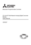
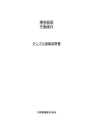
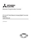
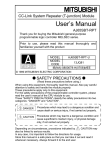
(1) Wiring to a terminal block for analog input signals
Câblage à une plaque à bornes pour signaux d'entrée analogiques
For voltage input
For current input
[Précautions de mise au rebut]
ATTENTION
● Lors de sa mise au rebut, ce produit doit être traité comme un déchet industriel.
CONDITIONS OF USE FOR THE PRODUCT
(1) Mitsubishi programmable controller ("the PRODUCT") shall be used in
conditions;
i) where any problem, fault or failure occurring in the PRODUCT, if any, shall
not lead to any major or serious accident; and
ii) where the backup and fail-safe function are systematically or automatically
provided outside of the PRODUCT for the case of any problem, fault or
failure occurring in the PRODUCT.
(2) The PRODUCT has been designed and manufactured for the purpose of being
used in general industries.
MITSUBISHI SHALL HAVE NO RESPONSIBILITY OR LIABILITY (INCLUDING,
BUT NOT LIMITED TO ANY AND ALL RESPONSIBILITY OR LIABILITY
BASED ON CONTRACT, WARRANTY, TORT, PRODUCT LIABILITY) FOR
ANY INJURY OR DEATH TO PERSONS OR LOSS OR DAMAGE TO
PROPERTY CAUSED BY the PRODUCT THAT ARE OPERATED OR USED IN
• To ensure electrical contact between the inner plate and control panel,
take measures such as covering the bolts so that conductivity can be
ensured in the largest possible area.
• Ground the control panel with a thick ground cable so that low
impedance can be ensured even at high frequencies.
• Holes in the control panel must be 10cm diameter or less. If the holes
are larger than 10cm, radio wave may be emitted. In addition, because
radio waves leak through a clearance between the control panel and its
door, reduce the clearance as much as possible. The leakage of radio
waves can be suppressed by the direct application of an EMI gasket on
the paint surface.
Our tests have been carried out on a panel having the attenuation
characteristics of 37 dB (max.) and 30 dB (mean) (measured by 3m
method, 30 to 300MHz).
(b) Wiring of power cables and ground cables
Near the power supply part, provide a ground point to the control panel.
Ground the FG terminal with the thickest and shortest possible ground
cable (30cm or shorter).
(3) Cables
Use shielded cables for the cables which are connected to the module and run
out from the control panel.
If a shielded cable is not used or not grounded correctly, the noise immunity
will not meet the specified value.
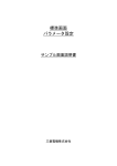
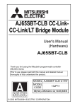
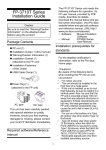
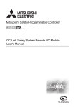
(a) Cables for the CC-Link IE Field Network
The precautions for using CC-Link IE Field Network cables are described
below.
• Shielded cables should be used for the CC-Link IE Field Network. Strip
a part of the jacket as shown below and ground the exposed shield in
the largest possible area.
Shield
CC-Link IE Field Network cable
(b) Grounding the cable clamp
Use shielded cables for external wiring and ground the shields of the
external wiring cables to the control panel with the AD75CK-type cable
clamp (Mitsubishi). (Ground the shield section 20 to 30cm away from the
module.)
Inside
the control panel
Module
20 to 30cm
AD75CK
For details of the AD75CK, refer to the following.
• AD75CK-type Cable Clamping Instruction Manual
(c) Analog I/O signal line
Use a signal line of 30m or shorter when connecting it to the analog I/O
terminals of the module.
(4) External power supply
• Use a CE-marked product for an external power supply and always ground
the FG terminal. (External power supply used for the tests conducted by
Mitsubishi: TDK-Lambda DLP-120-24-1, IDEC PS5R-SF24, PS5R-F24)
• Use a power cable of 10m or shorter when connecting it to the module power
supply terminal.
(5) Others
(a) Ferrite core
A ferrite core has the effect of reducing radiated noise in the 30MHz to
100MHz band. It is recommended to attach ferrite cores if shield cables
coming out of the control panel do not provide sufficient shielding effects.
Note that the ferrite cores must be attached at the position closest to the
cable hole inside the control panel. If attached at an improper position, the
ferrite core will not produce any effect.
For the FG terminal on a main module that is connected to the external
power supply, the external power supply of an extension module, and
CC-Link IE Field Network cables, attach a ferrite core 4cm away from the
module. (Ferrite core used for the tests conducted by Mitsubishi: NEC
TOKIN ESD-SR-250, TDK ZCAT3035-1330)
Example
*2
NC
NC
ATTENTION
● Ne pas démonter ni modifier le module. Cela pourrait entraîner des pannes ou
dysfonctionnements et être à l'origine de blessures ou de départs de feu.
● Ne pas faire tomber le module et ne pas le soumettre à des chocs. Cela risquerait
d'endommager le module.
● Couper l'alimentation externe du système (sur toutes les phases) avant de mettre
en place ou de retirer un module. Le non-respect de cette précaution peut être à
l'origine de pannes ou de dysfonctionnements du module.
● Après la première mise en service du produit (connecteur), le nombre maximum
admissible d'opérations de connexion/déconnexion est de 50 (selon IEC 61131-2).
● Avant de manipuler le module où le câble à raccorder au module, se débarrasser
de la charge électrostatique qu'accumule le corps humain en touchant un objet
conducteur comme une barre de mise à la terre. Le non-respect de cette
précaution peut être à l'origine de pannes ou de dysfonctionnements du module.
● La mise en service et la maintenance des tableaux de commande doivent être
effectuées par un personnel de maintenance qualifié et formé à la protection
contre les chocs électriques. Les tableaux de commande doivent être fermés à
clef pour n'être accessibles qu'à un personnel de maintenance qualifié.
Quantity
1
1
NC
NC
CH1
CH1 V+
COM CH1
SLD I+
CH2
CH2 V+
COM CH2
CH3 I+
V+ CH3
CH3 COM
I+
SLD
CH4
V+ CH4
CH4 COM
I+
AG
FG1
CH1
*3
*1
CH2
CH3
CH4
*4
English
For voltage input
For current input
CH1
*3
*1
CH2
CH3
CH4
*4
CH1
CH1 V+
COM CH1
SLD I+
CH2
CH2 V+
COM CH2
CH3 I+
V+ CH3
CH3 COM
I+
SLD
CH4
V+ CH4
CH4 COM
I+
AG
FG1
French
Pour entrée de tension
Pour entrée de courant
*1 For the wire, use the shielded twisted pair cable.
*2 For current input, connect the terminals (V+) and (I+).
*3 If noise or ripple occurs for external wiring, connect a capacitor with the value of
0.1 to 0.47µF (withstand voltage 25V or higher) between terminal (V+) and COM.
*4 Grand the FG1 terminal without fail. In electrically noisy environments, grounding
the AG terminal as well may be effective. When changing the grounding status of
the AG terminal after setting the offset/gain values, set the value again.
*1 Comme conducteur, utiliser une paire torsadée blindée.
*2 Pour l'entrée de courant, raccorder les bornes (V+) et (I+).
*3 S'il y a un phénomène de bruit ou d'ondulation sur le câblage externe, raccorder
un condensateur d'une capacité de 0,1μF à 0,47μF (tension de tenue de 25V ou
plus) entre la borne (V+) et COM.
*4 Ne pas oublier de mettre la borne FG1 à la masse. Dans un environnement
exposé aux interférences électriques, il peut être utile de mettre aussi la borne AG
à la masse. Si la borne AG est connectée à ou déconnectée de la masse après les
réglages offset/gain, il faut refaire ces réglages.
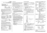
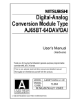
Input side
Input side
(power supply (power supply
side)
side)
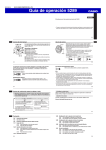
Induction
Filter
Output side
(device side)
Noise will be induced when the
input and output wires are bundled.
Filter
Output side
(device side)
Separately install the input and
output wires.
• Ground the noise filter grounding terminal to the control panel with the
shortest cable possible (approx. 10cm).
5.2 Requirements to Compliance with the Low Voltage Directive
The module operates at the rated voltage of 24VDC. The Low Voltage Directive is
not applied to the modules that operate at the rated voltage of less than 50VAC and
75VDC.
6. Information and services
For further information and services, please consult your local Mitsubishi
representative.
WARRANTY
Please confirm the following product warranty details before using this product.
1. Gratis Warranty Term and Gratis Warranty Range
If any faults or defects (hereinafter "Failure") found to be the responsibility of
Mitsubishi occurs during use of the product within the gratis warranty term, the
product shall be repaired at no cost via the sales representative or Mitsubishi
Service Company.
However, if repairs are required onsite at domestic or overseas location, expenses
to send an engineer will be solely at the customer's discretion. Mitsubishi shall not
be held responsible for any re-commissioning, maintenance, or testing on-site that
involves replacement of the failed module.
[Gratis Warranty Term]
The gratis warranty term of the product shall be for one year after the date of
purchase or delivery to a designated place.
Note that after manufacture and shipment from Mitsubishi, the maximum
distribution period shall be six (6) months, and the longest gratis warranty term after
manufacturing shall be eighteen (18) months. The gratis warranty term of repair
parts shall not exceed the gratis warranty term before repairs.
[Gratis Warranty Range]
(1) The range shall be limited to normal use within the usage state, usage methods
and usage environment, etc., which follow the conditions and precautions, etc.,
given in the instruction manual, user's manual and caution labels on the
product.
(2) Even within the gratis warranty term, repairs shall be charged for in the
following cases.
1. Failure occurring from inappropriate storage or handling, carelessness or
negligence by the user. Failure caused by the user's hardware or software
design.
2. Failure caused by unapproved modifications, etc., to the product by the user.
3. When the Mitsubishi product is assembled into a user's device, Failure that
could have been avoided if functions or structures, judged as necessary in
the legal safety measures the user's device is subject to or as necessary by
industry standards, had been provided.
4. Failure that could have been avoided if consumable parts (battery, backlight,
fuse, etc.) designated in the instruction manual had been correctly serviced
or replaced.
5. Failure caused by external irresistible forces such as fires or abnormal
voltages, and Failure caused by force majeure such as earthquakes,
lightning, wind and water damage.
6. Failure caused by reasons unpredictable by scientific technology standards
at time of shipment from Mitsubishi.
7. Any other failure found not to be the responsibility of Mitsubishi or that
admitted not to be so by the user.
2. Onerous repair term after discontinuation of production
(1) Mitsubishi shall accept onerous product repairs for seven (7) years after
production of the product is discontinued.
Discontinuation of production shall be notified with Mitsubishi Technical
Bulletins, etc.
(2) Product supply (including repair parts) is not available after production is
discontinued.
3. Overseas service
Overseas, repairs shall be accepted by Mitsubishi's local overseas FA Center. Note
that the repair conditions at each FA Center may differ.
4. Exclusion of loss in opportunity and secondary loss from
warranty liability
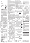
(b) Noise filter (power supply line filter)
A noise filter is a component which has an effect on conducted noise.
Attaching the filter can suppress more noise. (The noise filter has the
effect of reducing conducted noise of 10 MHz or less.)
Connect a noise filter to the external power supply of a main module and
the external power supply of an extension module. Use a noise filter with
the damping characteristics equivalent to those of MA1206 (manufactured
by TDK-Lambda Corporation). Note that a noise filter is not required if the
module is used in Zone A defined in EN61131-2.
The precautions for attaching a noise filter are described below.
• Do not bundle the cables on the input side and output side of the noise
filter. If bundled, the output side noise will be induced into the input side
cables from which the noise was filtered.
Regardless of the gratis warranty term, Mitsubishi shall not be liable for
compensation of damages caused by any cause found not to be the responsibility
of Mitsubishi, loss in opportunity, lost profits incurred to the user by Failures of
Mitsubishi products, special damages and secondary damages whether
foreseeable or not, compensation for accidents, and compensation for damages to
products other than Mitsubishi products, replacement by the user, maintenance of
on-site equipment, start-up test run and other tasks.
5. Changes in product specifications
The specifications given in the catalogs, manuals or technical documents are
subject to change without prior notice.