1
CC-Link IE Field Network Analog-Digital Converter
Module
User's Manual
-NZ2GF2BN-60AD4
-NZ2EX2B-60AD4
SAFETY PRECAUTIONS
(Read these precautions before using this product.)
Before using this product, please read this manual and the relevant manuals carefully and pay full attention
to safety to handle the product correctly.
The precautions given in this manual are concerned with this product only. For the safety precautions of the
programmable controller system, refer to the user's manual for the CPU module used.
In this manual, the safety precautions are classified into two levels: "
WARNING" and "
CAUTION".
WARNING
Indicates that incorrect handling may cause hazardous conditions,
resulting in death or severe injury.
CAUTION
Indicates that incorrect handling may cause hazardous conditions,
resulting in minor or moderate injury or property damage.
Under some circumstances, failure to observe the precautions given under "
CAUTION" may lead to
serious consequences.
Observe the precautions of both levels because they are important for personal and system safety.
Make sure that the end users read this manual and then keep the manual in a safe place for future
reference.
[Design Precautions]
WARNING
● When a communication failure occurs in the network, data in the master module are held. Check Data
link status (each station) (SW00B0 to SW00B7) and configure an interlock circuit in the program to
ensure that the entire system will operate safely.
● Do not use any "use prohibited" signals as a remote input or output signal. Do not write any data to the
"use prohibited" areas in the remote register. If these operations are performed, correct operation of
the module cannot be guaranteed.
[Design Precautions]
CAUTION
● Do not install the control lines or communication cables together with the main circuit lines or power
cables. Keep a distance of 100mm or more between them. Failure to do so may result in malfunction
due to noise.
1
[Installation Precautions]
WARNING
● Shut off the external power supply (all phases) used in the system before mounting or removing a
module. Failure to do so may result in electric shock or cause the module to fail or malfunction.
[Installation Precautions]
CAUTION
● Use the module in an environment that meets the general specifications in this manual. Failure to do
so may result in electric shock, fire, malfunction, or damage to or deterioration of the product.
● Do not directly touch any conductive parts and electronic components of the module. Doing so can
cause malfunction or failure of the module.
● Securely fix the module with a DIN rail.
● After the first use of the product (extension module), the number of connections/disconnections is
limited to 50 times (IEC 61131-2 compliant).
● To connect an extension module to a main module, engage the respective connectors and securely
lock the module joint levers. Incorrect connection may cause malfunction, failure, or drop of the
module.
● Securely connect the cable connectors. Poor contact may cause malfunction.
2
[Wiring Precautions]
WARNING
● Shut off the external power supply (all phases) used in the system before wiring. Failure to do so may
result in electric shock or cause the module to fail or malfunction.
[Wiring Precautions]
CAUTION
● Individually ground the FG terminal of the programmable controller with a ground resistance of 100
ohms or less. Failure to do so may result in electric shock or malfunction.
● Tighten any unused terminal screws within the specified torque range. Undertightening can cause a
short circuit due to contact with a solderless terminal.
● Use applicable solderless terminals and tighten them within the specified torque range. If any spade
solderless terminal is used, it may be disconnected when a terminal block screw comes loose,
resulting in failure.
● Check the rated voltage and terminal layout before wiring to the module, and connect the cables
correctly. Connecting a power supply with a different voltage rating or incorrect wiring may cause a fire
or failure.
● Tighten the terminal block screws within the specified torque range. Undertightening can cause short
circuit, fire, or malfunction. Overtightening can damage the screw and/or module, resulting in drop,
short circuit, fire, or malfunction.
● Prevent foreign matter such as dust or wire chips from entering the module. Such foreign matter can
cause a fire, failure, or malfunction.
● Place the cables in a duct or clamp them. If not, dangling cable may swing or inadvertently be pulled,
resulting in damage to the module or cables or malfunction due to poor contact.
● Do not install the control lines or communication cables together with the main circuit lines or power
cables. Keep a distance of 100mm or more between them. Failure to do so may result in malfunction
due to noise.
● When disconnecting the cable from the module, do not pull the cable by the cable part. For the cable
with connector, hold the connector part of the cable. For the cable connected to the terminal block,
loosen the terminal screw. Pulling the cable connected to the module may result in malfunction or
damage to the module or cable.
● When an overcurrent caused by an error of an external device or a failure of the programmable
controller flows for a long time, it may cause smoke and fire. To prevent this, configure an external
safety circuit, such as a fuse.
● Mitsubishi programmable controllers must be installed in control panels. Wiring and replacement of a
module must be performed by qualified maintenance personnel with knowledge of protection against
electric shock. For wiring methods, refer to "INSTALLATION AND WIRING" in this manual.
3
[Startup and Maintenance Precautions]
WARNING
● Do not touch any terminal while power is on. Doing so will cause electric shock or malfunction.
● Shut off the external power supply (all phases) used in the system before cleaning the module or
retightening the terminal block screws or connector screws. Failure to do so may cause the module to
fail or malfunction.
[Startup and Maintenance Precautions]
CAUTION
● Do not disassemble or modify the module. Doing so may cause failure, malfunction, injury, or a fire.
● Do not drop or apply strong shock to the module. Doing so may damage the module.
● Shut off the external power supply (all phases) used in the system before mounting or removing a
module. Failure to do so may cause the module to fail or malfunction.
● After the first use of the product, do not connect/disconnect the terminal block more than 50 times (in
accordance with IEC 61131-2).
● Before handling the module or connection cables, touch a conducting object such as a grounded
metal to discharge the static electricity from the human body. Failure to do so may cause the module
to fail or malfunction.
● Startup and maintenance of a control panel must be performed by qualified maintenance personnel
with knowledge of protection against electric shock. Lock the control panel so that only qualified
maintenance personnel can operate it.
[Disposal Precautions]
CAUTION
● When disposing of this product, treat it as industrial waste.
4
CONDITIONS OF USE FOR THE PRODUCT
1) Mitsubishi programmable controller ("the PRODUCT") shall be used in conditions;
i) where any problem, fault or failure occurring in the PRODUCT, if any, shall not lead to any major or serious accident;
and
ii) where the backup and fail-safe function are systematically or automatically provided outside of the PRODUCT for the
case of any problem, fault or failure occurring in the PRODUCT.
2) The PRODUCT has been designed and manufactured for the purpose of being used in general industries.
MITSUBISHI SHALL HAVE NO RESPONSIBILITY OR LIABILITY (INCLUDING, BUT NOT LIMITED TO ANY AND ALL
RESPONSIBILITY OR LIABILITY BASED ON CONTRACT, WARRANTY, TORT, PRODUCT LIABILITY) FOR ANY
INJURY OR DEATH TO PERSONS OR LOSS OR DAMAGE TO PROPERTY CAUSED BY the PRODUCT THAT ARE
OPERATED OR USED IN APPLICATION NOT INTENDED OR EXCLUDED BY INSTRUCTIONS, PRECAUTIONS, OR
WARNING CONTAINED IN MITSUBISHI'S USER, INSTRUCTION AND/OR SAFETY MANUALS, TECHNICAL
BULLETINS AND GUIDELINES FOR the PRODUCT.
("Prohibited Application")
Prohibited Applications include, but not limited to, the use of the PRODUCT in;
• Nuclear Power Plants and any other power plants operated by Power companies, and/or any other cases in which the
public could be affected if any problem or fault occurs in the PRODUCT.
• Railway companies or Public service purposes, and/or any other cases in which establishment of a special quality
assurance system is required by the Purchaser or End User.
• Aircraft or Aerospace, Medical applications, Train equipment, transport equipment such as Elevator and Escalator,
Incineration and Fuel devices, Vehicles, Manned transportation, Equipment for Recreation and Amusement, and
Safety devices, handling of Nuclear or Hazardous Materials or Chemicals, Mining and Drilling, and/or other
applications where there is a significant risk of injury to the public or property.
Notwithstanding the above, restrictions Mitsubishi may in its sole discretion, authorize use of the PRODUCT in one or
more of the Prohibited Applications, provided that the usage of the PRODUCT is limited only for the specific
applications agreed to by Mitsubishi and provided further that no special quality assurance or fail-safe, redundant or
other safety features which exceed the general specifications of the PRODUCTs are required. For details, please
contact the Mitsubishi representative in your region.
5
INTRODUCTION
Thank you for purchasing the CC-Link IE Field Network analog-digital converter module (hereafter abbreviated as A/D
converter module).
This manual describes the operating procedure, system configuration, parameter settings, functions, and
troubleshooting of the A/D converter module.
Before using this product, please read this manual and the relevant manuals carefully and develop familiarity with the
functions and performance of the A/D converter module to handle the product correctly.
When applying the program examples introduced in this manual to an actual system, ensure the applicability and
confirm that it will not cause system control problems.
Relevant modules: NZ2GF2BN-60AD4, NZ2EX2B-60AD4
Remark
Unless otherwise specified, this manual describes the program examples in which the remote I/O signals and remote
registers are assigned for an A/D converter module as follows.
• Remote input signal: RX0 to RX1F (main A/D converter module), RX20 to RX2F (extension A/D converter
module)
• Remote output signal: RY0 to RY1F (main A/D converter module), RY20 to RY2F (extension A/D converter
module)
• Remote register (RWr): RWr0 to RWrF (main A/D converter module), RWr10 to RWr1F (extension A/D converter
module)
• Remote register (RWw): RWw0 to RWwF (main A/D converter module), RWw10 to RWw1F (extension A/D
converter module)
For the assignment of remote I/O signals and remote registers, refer to the following.
User's manual for the master/local module used
6
RELEVANT MANUALS
(1) CC-Link IE Field Network (relevant) manuals
When using the CC-Link IE Field Network for the first time, refer to CC-Link IE Field Network Master/Local
Module User's Manual or Simple Motion Module User's Manual first. The following shows the structure of the CCLink IE Field Network manuals.
Manual name
<manual number (model code)>
Description
MELSEC-Q CC-Link IE Field Network Master/Local Module User's Manual
[SH-080917ENG, 13JZ47]
Overview of the CC-Link IE Field Network, and specifications, procedures
before operation, system configuration, installation, wiring, settings, functions,
programming, and troubleshooting of the QJ71GF11-T2
MELSEC-L CC-Link IE Field Network Master/Local Module User's Manual
[SH-080972ENG, 13JZ54]
Overview of the CC-Link IE Field Network, and specifications, procedures
before operation, system configuration, installation, wiring, settings, functions,
programming, and troubleshooting of the LJ71GF11-T2
MELSEC iQ-R Ethernet/CC-Link IE User's Manual (Startup)
[SH-081256ENG, 13JX09]
Specifications, procedures before operation, system configuration, wiring, and
communication examples of Ethernet, CC-Link IE Controller Network, and
CC-Link IE Field Network
MELSEC iQ-R CC-Link IE Field Network User's Manual (Application)
[SH-081259ENG, 13JX18]
Functions, parameter settings, programming, troubleshooting, I/O signals, and
buffer memory of CC-Link IE Field Network
MELSEC iQ-R Inter-Module Synchronization Function Reference Manual
[SH-081401ENG]
Inter-module synchronization function, which controls multiple modules
synchronously
MELSEC-Q QD77GF Simple Motion Module User's Manual (Network)
[IB-0300203, 1XB957]
Functions, programming, and troubleshooting for CC-Link IE Field Network of
the QD77GF16
MELSEC-Q QD77GF Simple Motion Module User's Manual (Positioning
Control)
[IB-0300202, 1XB956]
Specifications of the QD77GF16 and information on how to establish a
system, maintenance and inspection, and troubleshooting.
Also included are functions, programming and buffer memory for the
positioning control of the QD77GF16.
CC-Link IE Field Network Remote I/O Module User's Manual
[SH-081114ENG, 13JZ82]
Specifications, procedures before operation, system configuration, installation,
wiring, various settings, functions, programming, and troubleshooting of the
CC-Link IE Field Network remote I/O module
CC-Link IE Field Network Digital-Analog Converter Module User's Manual
[SH-081453ENG, 13JX27]
Specifications, procedures before operation, system configuration, installation,
wiring, various settings, functions, programming, and troubleshooting of the
CC-Link IE Field Network digital-analog converter module
(2) Operating manual
Manual name
<manual number (model code)>
Description
GX Works2 Version 1 Operating Manual (Common)
[SH-080779ENG, 13JU63]
System configuration, parameter settings, and online operations of GX
Works2, which are common to Simple projects and Structured projects
GX Works3 Operating Manual
[SH-081215ENG]
System configuration, parameter settings, and online operations of GX
Works3
7
CONTENTS
CONTENTS
SAFETY PRECAUTIONS . . . . . . . . . . . . . . . . . . . . . . . . . . . . . . . . . . . . . . . . . . . . . . . . . . . . . . . . . . . . . 1
CONDITIONS OF USE FOR THE PRODUCT . . . . . . . . . . . . . . . . . . . . . . . . . . . . . . . . . . . . . . . . . . . . . 5
INTRODUCTION . . . . . . . . . . . . . . . . . . . . . . . . . . . . . . . . . . . . . . . . . . . . . . . . . . . . . . . . . . . . . . . . . . . . 6
RELEVANT MANUALS . . . . . . . . . . . . . . . . . . . . . . . . . . . . . . . . . . . . . . . . . . . . . . . . . . . . . . . . . . . . . . . 7
MANUAL PAGE ORGANIZATION . . . . . . . . . . . . . . . . . . . . . . . . . . . . . . . . . . . . . . . . . . . . . . . . . . . . . . 11
TERMS . . . . . . . . . . . . . . . . . . . . . . . . . . . . . . . . . . . . . . . . . . . . . . . . . . . . . . . . . . . . . . . . . . . . . . . . . . 12
PACKING LIST . . . . . . . . . . . . . . . . . . . . . . . . . . . . . . . . . . . . . . . . . . . . . . . . . . . . . . . . . . . . . . . . . . . . 14
CHAPTER 1 A/D CONVERTER MODULE
1.1
Application . . . . . . . . . . . . . . . . . . . . . . . . . . . . . . . . . . . . . . . . . . . . . . . . . . . . . . . . . . . . . . . . 15
1.2
Features . . . . . . . . . . . . . . . . . . . . . . . . . . . . . . . . . . . . . . . . . . . . . . . . . . . . . . . . . . . . . . . . . . 16
CHAPTER 2 PART NAMES
20
2.1
Main A/D Converter Module . . . . . . . . . . . . . . . . . . . . . . . . . . . . . . . . . . . . . . . . . . . . . . . . . . . 20
2.2
Extension A/D Converter Module . . . . . . . . . . . . . . . . . . . . . . . . . . . . . . . . . . . . . . . . . . . . . . . 23
CHAPTER 3 SPECIFICATIONS
24
3.1
General Specifications . . . . . . . . . . . . . . . . . . . . . . . . . . . . . . . . . . . . . . . . . . . . . . . . . . . . . . . 24
3.2
Performance Specifications . . . . . . . . . . . . . . . . . . . . . . . . . . . . . . . . . . . . . . . . . . . . . . . . . . . 25
3.2.1
Main A/D converter module . . . . . . . . . . . . . . . . . . . . . . . . . . . . . . . . . . . . . . . . . . . . . . . . . . .25
3.2.2
Extension A/D Converter Module. . . . . . . . . . . . . . . . . . . . . . . . . . . . . . . . . . . . . . . . . . . . . . .27
3.3
How to Calculate Current Consumption . . . . . . . . . . . . . . . . . . . . . . . . . . . . . . . . . . . . . . . . . . 29
3.4
Function List . . . . . . . . . . . . . . . . . . . . . . . . . . . . . . . . . . . . . . . . . . . . . . . . . . . . . . . . . . . . . . . 30
3.5
3.6
3.7
List of Remote I/O Signals . . . . . . . . . . . . . . . . . . . . . . . . . . . . . . . . . . . . . . . . . . . . . . . . . . . . 32
3.5.1
Main A/D converter module . . . . . . . . . . . . . . . . . . . . . . . . . . . . . . . . . . . . . . . . . . . . . . . . . . .33
3.5.2
Extension A/D converter module . . . . . . . . . . . . . . . . . . . . . . . . . . . . . . . . . . . . . . . . . . . . . . .34
List of Remote Registers . . . . . . . . . . . . . . . . . . . . . . . . . . . . . . . . . . . . . . . . . . . . . . . . . . . . . 35
3.6.1
Main A/D converter module . . . . . . . . . . . . . . . . . . . . . . . . . . . . . . . . . . . . . . . . . . . . . . . . . . .36
3.6.2
Extension A/D converter module . . . . . . . . . . . . . . . . . . . . . . . . . . . . . . . . . . . . . . . . . . . . . . .37
List of Remote Buffer Memory Areas . . . . . . . . . . . . . . . . . . . . . . . . . . . . . . . . . . . . . . . . . . . . 38
3.7.1
Main A/D converter module . . . . . . . . . . . . . . . . . . . . . . . . . . . . . . . . . . . . . . . . . . . . . . . . . . .39
3.7.2
Extension A/D converter module . . . . . . . . . . . . . . . . . . . . . . . . . . . . . . . . . . . . . . . . . . . . . . .44
CHAPTER 4 PROCEDURES BEFORE OPERATION
46
CHAPTER 5 SYSTEM CONFIGURATION
48
5.1
System Configuration with A/D Converter Module . . . . . . . . . . . . . . . . . . . . . . . . . . . . . . . . . . 48
5.2
Applicable Systems . . . . . . . . . . . . . . . . . . . . . . . . . . . . . . . . . . . . . . . . . . . . . . . . . . . . . . . . . 49
CHAPTER 6 INSTALLATION AND WIRING
8
15
50
6.1
Station Number Setting. . . . . . . . . . . . . . . . . . . . . . . . . . . . . . . . . . . . . . . . . . . . . . . . . . . . . . . 50
6.2
Installation Environment and Installation Position . . . . . . . . . . . . . . . . . . . . . . . . . . . . . . . . . . 51
6.2.1
Installation environment . . . . . . . . . . . . . . . . . . . . . . . . . . . . . . . . . . . . . . . . . . . . . . . . . . . . . .51
6.2.2
Installation position. . . . . . . . . . . . . . . . . . . . . . . . . . . . . . . . . . . . . . . . . . . . . . . . . . . . . . . . . .51
6.2.3
6.3
Installation direction . . . . . . . . . . . . . . . . . . . . . . . . . . . . . . . . . . . . . . . . . . . . . . . . . . . . . . . . .52
Installation. . . . . . . . . . . . . . . . . . . . . . . . . . . . . . . . . . . . . . . . . . . . . . . . . . . . . . . . . . . . . . . . . 53
6.3.1
How to connect an extension module . . . . . . . . . . . . . . . . . . . . . . . . . . . . . . . . . . . . . . . . . . .53
6.3.2
How to mount modules on a DIN rail . . . . . . . . . . . . . . . . . . . . . . . . . . . . . . . . . . . . . . . . . . . .55
6.4
Wiring to Terminal Block for Module Power Supply and FG . . . . . . . . . . . . . . . . . . . . . . . . . . . 58
6.5
Wiring of Ethernet Cable. . . . . . . . . . . . . . . . . . . . . . . . . . . . . . . . . . . . . . . . . . . . . . . . . . . . . . 60
6.6
Wiring of Terminal Block and External Devices . . . . . . . . . . . . . . . . . . . . . . . . . . . . . . . . . . . . 63
CHAPTER 7 VARIOUS SETTINGS
7.1
7.2
7.3
69
Parameter Settings . . . . . . . . . . . . . . . . . . . . . . . . . . . . . . . . . . . . . . . . . . . . . . . . . . . . . . . . . . 69
How to Change the Parameters . . . . . . . . . . . . . . . . . . . . . . . . . . . . . . . . . . . . . . . . . . . . . . . . 76
7.2.1
Changing the network configuration. . . . . . . . . . . . . . . . . . . . . . . . . . . . . . . . . . . . . . . . . . . . .76
7.2.2
Changing the parameters without changing the network configuration . . . . . . . . . . . . . . . . . .80
Offset/Gain Setting . . . . . . . . . . . . . . . . . . . . . . . . . . . . . . . . . . . . . . . . . . . . . . . . . . . . . . . . . . 83
CHAPTER 8 FUNCTIONS
85
8.1
Mode Shift at Power-On . . . . . . . . . . . . . . . . . . . . . . . . . . . . . . . . . . . . . . . . . . . . . . . . . . . . . . 85
8.2
Drive Mode Switch . . . . . . . . . . . . . . . . . . . . . . . . . . . . . . . . . . . . . . . . . . . . . . . . . . . . . . . . . . 86
8.3
Each Function in the Sequence . . . . . . . . . . . . . . . . . . . . . . . . . . . . . . . . . . . . . . . . . . . . . . . . 88
8.4
A/D Conversion Enable/Disable Function. . . . . . . . . . . . . . . . . . . . . . . . . . . . . . . . . . . . . . . . . 89
8.5
Conversion Speed Switch Function . . . . . . . . . . . . . . . . . . . . . . . . . . . . . . . . . . . . . . . . . . . . . 89
8.5.1
Conversion Speed and Sampling Period . . . . . . . . . . . . . . . . . . . . . . . . . . . . . . . . . . . . . . . . .90
8.6
A/D Conversion Method . . . . . . . . . . . . . . . . . . . . . . . . . . . . . . . . . . . . . . . . . . . . . . . . . . . . . . 95
8.7
Range Switching Function . . . . . . . . . . . . . . . . . . . . . . . . . . . . . . . . . . . . . . . . . . . . . . . . . . . . 99
8.8
Maximum Value/Minimum Value Hold Function . . . . . . . . . . . . . . . . . . . . . . . . . . . . . . . . . . . 100
8.9
Input Signal Error Detection Function. . . . . . . . . . . . . . . . . . . . . . . . . . . . . . . . . . . . . . . . . . . 101
8.10
Alert Output Function (Process Alarm) . . . . . . . . . . . . . . . . . . . . . . . . . . . . . . . . . . . . . . . . . . 105
8.11
Scaling Function . . . . . . . . . . . . . . . . . . . . . . . . . . . . . . . . . . . . . . . . . . . . . . . . . . . . . . . . . . . 108
8.12
Shift Function . . . . . . . . . . . . . . . . . . . . . . . . . . . . . . . . . . . . . . . . . . . . . . . . . . . . . . . . . . . . . 113
8.13
Digital Clipping Function . . . . . . . . . . . . . . . . . . . . . . . . . . . . . . . . . . . . . . . . . . . . . . . . . . . . . 117
8.14
Difference Conversion Function . . . . . . . . . . . . . . . . . . . . . . . . . . . . . . . . . . . . . . . . . . . . . . . 122
8.15
Trigger Conversion Function . . . . . . . . . . . . . . . . . . . . . . . . . . . . . . . . . . . . . . . . . . . . . . . . . 127
8.16
CC-Link IE Field Network Synchronous Communication Function. . . . . . . . . . . . . . . . . . . . . 135
8.17
Error Notification Function . . . . . . . . . . . . . . . . . . . . . . . . . . . . . . . . . . . . . . . . . . . . . . . . . . . 142
8.18
Functions with an Extension Module Connected . . . . . . . . . . . . . . . . . . . . . . . . . . . . . . . . . . 145
8.18.1 Functions with an extension I/O module connected. . . . . . . . . . . . . . . . . . . . . . . . . . . . . . . .145
8.18.2 Functions with the extension A/D converter module connected . . . . . . . . . . . . . . . . . . . . . .150
8.18.3 Functions with the extension D/A converter module connected . . . . . . . . . . . . . . . . . . . . . .151
8.19
CC-Link IE Field Network Diagnostic Function. . . . . . . . . . . . . . . . . . . . . . . . . . . . . . . . . . . . 152
CHAPTER 9 PROGRAMMING
155
9.1
Precautions for Programming . . . . . . . . . . . . . . . . . . . . . . . . . . . . . . . . . . . . . . . . . . . . . . . . . 155
9.2
Programming Procedure. . . . . . . . . . . . . . . . . . . . . . . . . . . . . . . . . . . . . . . . . . . . . . . . . . . . . 156
9.3
Program Example . . . . . . . . . . . . . . . . . . . . . . . . . . . . . . . . . . . . . . . . . . . . . . . . . . . . . . . . . . 156
9
CHAPTER 10 MAINTENANCE AND INSPECTION
166
CHAPTER 11 TROUBLESHOOTING
168
11.1
11.2
11.3
11.4
How to Check Error Codes and Alarm Codes . . . . . . . . . . . . . . . . . . . . . . . . . . . . . . . . . . . . 168
Error Code List . . . . . . . . . . . . . . . . . . . . . . . . . . . . . . . . . . . . . . . . . . . . . . . . . . . . . . . . . . . . 172
11.2.1
Main A/D converter module . . . . . . . . . . . . . . . . . . . . . . . . . . . . . . . . . . . . . . . . . . . . . . . . . .173
11.2.2
Extension A/D converter module . . . . . . . . . . . . . . . . . . . . . . . . . . . . . . . . . . . . . . . . . . . . . .178
Alarm Code List . . . . . . . . . . . . . . . . . . . . . . . . . . . . . . . . . . . . . . . . . . . . . . . . . . . . . . . . . . . 180
11.3.1
Main A/D converter module . . . . . . . . . . . . . . . . . . . . . . . . . . . . . . . . . . . . . . . . . . . . . . . . . .180
11.3.2
Extension A/D converter module . . . . . . . . . . . . . . . . . . . . . . . . . . . . . . . . . . . . . . . . . . . . . .180
Checking the LEDs . . . . . . . . . . . . . . . . . . . . . . . . . . . . . . . . . . . . . . . . . . . . . . . . . . . . . . . . . 181
11.4.1
Main A/D converter module . . . . . . . . . . . . . . . . . . . . . . . . . . . . . . . . . . . . . . . . . . . . . . . . . .181
11.4.2
Extension A/D converter module . . . . . . . . . . . . . . . . . . . . . . . . . . . . . . . . . . . . . . . . . . . . . .184
11.5
Unit Test . . . . . . . . . . . . . . . . . . . . . . . . . . . . . . . . . . . . . . . . . . . . . . . . . . . . . . . . . . . . . . . . . 185
11.6
Troubleshooting by Symptom . . . . . . . . . . . . . . . . . . . . . . . . . . . . . . . . . . . . . . . . . . . . . . . . . 186
11.6.1
Main A/D converter module . . . . . . . . . . . . . . . . . . . . . . . . . . . . . . . . . . . . . . . . . . . . . . . . . .186
11.6.2
Extension A/D converter module . . . . . . . . . . . . . . . . . . . . . . . . . . . . . . . . . . . . . . . . . . . . . .188
APPENDICES
189
Appendix 1 Details of Remote I/O Signals . . . . . . . . . . . . . . . . . . . . . . . . . . . . . . . . . . . . . . . . . . . . 189
Appendix 1.1
Remote input signals . . . . . . . . . . . . . . . . . . . . . . . . . . . . . . . . . . . . . . . . . . . . . . . . .189
Appendix 1.2
Remote output signals . . . . . . . . . . . . . . . . . . . . . . . . . . . . . . . . . . . . . . . . . . . . . . . .198
Appendix 2 Details of Remote Registers . . . . . . . . . . . . . . . . . . . . . . . . . . . . . . . . . . . . . . . . . . . . . 201
Appendix 3 Details of Remote Buffer Memory . . . . . . . . . . . . . . . . . . . . . . . . . . . . . . . . . . . . . . . . . 205
Appendix 4 I/O Conversion Characteristics of A/D Conversion . . . . . . . . . . . . . . . . . . . . . . . . . . . . 229
Appendix 5 Accuracy of A/D Conversion . . . . . . . . . . . . . . . . . . . . . . . . . . . . . . . . . . . . . . . . . . . . . 232
Appendix 6 Processing Time of CC-Link IE Field Network . . . . . . . . . . . . . . . . . . . . . . . . . . . . . . . 233
Appendix 7 EMC and Low Voltage Directives . . . . . . . . . . . . . . . . . . . . . . . . . . . . . . . . . . . . . . . . . 234
Appendix 7.1
Measures to comply with the EMC Directive . . . . . . . . . . . . . . . . . . . . . . . . . . . . . . .234
Appendix 7.2
Requirements to compliance with the Low Voltage Directive. . . . . . . . . . . . . . . . . . .240
Appendix 8 How to Check Serial Number and Function Version . . . . . . . . . . . . . . . . . . . . . . . . . . . 241
Appendix 9 Comparison with NZ2GF2B-60AD4 . . . . . . . . . . . . . . . . . . . . . . . . . . . . . . . . . . . . . . . 242
Appendix 9.1
Comparison of performance specifications . . . . . . . . . . . . . . . . . . . . . . . . . . . . . . . .242
Appendix 9.2
Functional comparison . . . . . . . . . . . . . . . . . . . . . . . . . . . . . . . . . . . . . . . . . . . . . . . .242
Appendix 9.3
About replacement from NZ2GF2B-60AD4 to NZ2GF2BN-60AD4 . . . . . . . . . . . . . .243
Appendix 10 External Dimensions . . . . . . . . . . . . . . . . . . . . . . . . . . . . . . . . . . . . . . . . . . . . . . . . . . . 244
Appendix 10.1 Main A/D converter module . . . . . . . . . . . . . . . . . . . . . . . . . . . . . . . . . . . . . . . . . . . .244
Appendix 10.2 Extension A/D converter module . . . . . . . . . . . . . . . . . . . . . . . . . . . . . . . . . . . . . . . .244
INDEX
245
REVISIONS . . . . . . . . . . . . . . . . . . . . . . . . . . . . . . . . . . . . . . . . . . . . . . . . . . . . . . . . . . . . . . . . . . . . . . 248
WARRANTY . . . . . . . . . . . . . . . . . . . . . . . . . . . . . . . . . . . . . . . . . . . . . . . . . . . . . . . . . . . . . . . . . . . . . 249
TRADEMARKS . . . . . . . . . . . . . . . . . . . . . . . . . . . . . . . . . . . . . . . . . . . . . . . . . . . . . . . . . . . . . . . . . . . 250
10
MANUAL PAGE ORGANIZATION
In this manual, pages are organized and the symbols are used as shown below.
The following illustration is for explanation purpose only, and should not be referred to as an actual documentation.
"" is used for
window names and items.
The chapter of
the current page is shown.
shows operating
procedures.
shows mouse
operations.*1
[ ] is used for items
in the menu bar and
the project window.
The section of
the current page is shown.
Ex. shows setting or
operating examples.
shows reference
manuals.
shows notes that
require attention.
shows
reference pages.
shows useful
information.
*1
The mouse operation example is provided below.
Menu bar
Ex.
[Online]
[Write to PLC...]
Select [Online] on the menu bar,
and then select [Write to PLC...].
A window selected in the view selection area is displayed.
Ex.
[Parameter]
Project window
[PLC Parameter]
Select [Project] from the view selection
area to open the Project window.
In the Project window, expand [Parameter] and
select [PLC Parameter].
View selection area
11
TERMS
Unless otherwise specified, this manual uses the following terms.
Term
Description
A/D converter module
A generic term for the main A/D converter module and extension A/D converter module
Buffer memory
A memory in an intelligent function module, where data (such as setting values and monitoring values)
exchanged with a CPU module are stored
CC-Link IE Field Network
A high-speed and large-capacity open field network that is based on Ethernet (1000BASE-T)
Cyclic transmission
A function by which data are periodically exchanged among stations on the same network using link devices
(RX, RY, RWw, and RWr)
Data link
A generic term for cyclic transmission and transient transmission
Dedicated instruction
An instruction that simplifies programming for using functions of intelligent function modules
Disconnection
A process of stopping data link if a data link error occurs
Extension A/D converter module
The abbreviation for the NZ2EX2B-60AD4 CC-Link IE Field Network extension analog-digital converter
module
Extension analog module
A generic term for the extension A/D converter module and extension D/A converter module
Extension D/A converter module
The abbreviation for the NZ2EX2BN-60DA4 CC-Link IE Field Network extension digital-analog converter
module
Extension I/O module
A generic term for the extension input module and extension output module
Extension input module
A generic term for extension modules where digital signals can be input
Extension module
A remote module with no CC-Link IE Field Network communication function. This module cannot be used as a
single module. However, connecting the module to the main module will increase the number of I/O points per
station.
Extension output module
A generic term for extension modules where digital signals can be output
GX Works2
GX Works3
The product name of the software package for the MELSEC programmable controllers
I/O module
Another term for the CC-Link IE Field Network remote I/O module
Intelligent device station
A station that exchanges I/O signals (bit data) and I/O data (word data) with another station by cyclic
transmission. This station responds to a transient transmission request from another station and also issues a
transient transmission request to another station.
Link device
A device (RX, RY, RWr, or RWw) in a module on CC-Link IE Field Network
Link special register (SW)
Word data that indicates the operating status and data link status of a module on CC-Link IE Field Network
Link special relay (SB)
Bit data that indicates the operating status and data link status of a module on CC-Link IE Field Network
Local station
A station that performs cyclic transmission and transient transmission with the master station and other local
stations. The station is controlled by programs in the CPU module or other equivalent modules on the station.
Main A/D converter module
The abbreviation for the NZ2GF2BN-60AD4 CC-Link IE Field Network main analog-digital converter module
Main analog module
A generic term for the main A/D converter module and main D/A converter module
Main D/A converter module
The abbreviation for the NZ2GF2BN-60DA4 CC-Link IE Field Network main digital-analog converter module
Main module
A module with the CC-Link IE Field Network communication function, which can be used as a single remote
module.
Master station
A station that controls the entire network. This station can perform cyclic transmission and transient
transmission with all stations. Only one master station can be used in a network.
Master/local module
A generic term for the CC-Link IE Field Network master/local module
Network module
A generic term for the following modules:
• CC-Link IE Field Network module
• CC-Link IE Controller Network module
• Ethernet interface module
• MELSECNET/H module
• MELSECNET/10 module
Relay station
A station that includes two or more network modules. Data are passed through this station to stations on other
networks
REMFR
The abbreviation for ZP.REMFR.
Remote buffer memory
Buffer memory in a remote device station
Remote device station
A station that exchanges I/O signals (bit data) and I/O data (word data) with another station by cyclic
transmission. This station responds to a transient transmission request from another station.
Remote I/O station
A station that exchanges I/O signals (bit data) with the master station by cyclic transmission
12
Term
Description
Remote input (RX)
Bit data input from a slave station to the master station (For some areas in a local station, data are input in the
opposite direction.)
User's manual for the master/local module used
Remote output (RY)
Bit data output from the master station to a slave station (For some areas in a local station, data are output in
the opposite direction.)
User's manual for the master/local module used
Remote register (RWr)
Word data input from a slave station to the master station (For some areas in a local station, data are input in
the opposite direction.)
User's manual for the master/local module used
Remote register (RWw)
Word data output from the master station to a slave station (For some areas in a local station, data are output
in the opposite direction.)
User's manual for the master/local module used
REMTO
The abbreviation for ZP.REMTO.
Reserved station
A station reserved for future use. This station is not actually connected, but counted as a connected station
Return
A process of restarting data link when a station recovers from an error
Simple motion module
The abbreviation for the QD77GF CC-Link IE Field Network simple motion module
Slave station
A generic term for stations other than a master station: local station, remote I/O station, remote device station,
and intelligent device station
Transient transmission
A function of communication with another station, which is used when requested by a dedicated instruction or
GX Works2
13
PACKING LIST
The following items are included in the package of this product. Before use, check that all the items are included.
A/D converter module
Module (The figure above shows the main A/D converter module.)
14
Before Using the Product
CHAPTER 1 A/D CONVERTER MODULE
CHAPTER 1
A/D CONVERTER MODULE
1
This chapter describes the application and the features of the A/D converter module.
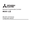
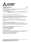
1.1
Application
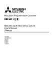
The A/D converter module converts analog values that are input from external devices to digital operation values.
A/D conversion
Analog signal as a continuous amount
Digital signal as a discrete sequence
The converted digital operation value can be checked in the master station.
Using the A/D converter module allows the flow or temperature measured by the A/D converter module to be checked
through the master station.
Master station
Master station
Control valve
1.1 Application
CC-Link IE Field Network
CC-Link IE Field Network
Flow control
Power conditioner
Tank
Heater
Main A/D converter module
Main A/D converter module
15
1.2
Features
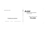
(1) Flexible system configuration
The employed connection block type provides the combined use of a main module and an extension module.
A flexible configuration can be achieved because various extension modules can be connected.
In addition, the main module always monitors the connection status of the extension module, leading to an early
detection of connection failure.
Various extension modules can be
connected according to the application.
No wiring of wires and Ethernet cables
is required.
Main module
Main A/D converter module
Extension module
Extension input module
Extension output module (sink type)
Extension output module (source type)
The flexible combination is possible.
Extension A/D converter module
Extension D/A converter module
(2) Easy setting of station numbers
Station numbers are set with the rotary switch on the front of the module, where setting and checking the station
numbers are easy.
(3) Selectable conversion speed
A/D conversion at 100s/channel meets the need of a high-speed conversion.
Under the environment in which noise is likely to occur, switching the conversion speed to 400s/channel or
1ms/channel minimizes the effect of noise on the digital operation value, the stability of which is improved.
16
CHAPTER 1 A/D CONVERTER MODULE
1
(4) A/D conversion at any desired timing
A/D conversion is performed once immediately after the input of a trigger conversion request to obtain the digital
operation value.
The combination with the external signal assignment function allows direct input of a trigger conversion request
from the extension input module, with the following advantages:
• Being free from the effect of the sequence scan and link scan, digital operation values can be constantly
obtained at a given timing, which leads to the improvement of the reliability.
• Digital operation values can be obtained without any program, which leads to a reduction in the cost of
creating a program.
Analog input signals (CH1 to CH4)
Displacement sensor
Extension input module
Main A/D converter module
Trigger conversion request by the external
signal assignment function
A/D conversion values can be converted to be within any scale, the range of which is determined arbitrarily.
According to the device that handles digital operation values, the scale can be changed without any program,
resulting in cost reduction.
(6) Detection of the disconnection
An input range of 1 to 5V, or 4 to 20mA allows the detection of the disconnection of analog input, facilitating the
diagnosis of the cause at the time of a trouble.
In combination with the external signal assignment function, the extension output module allows a signal (input
signal error detection signal) to be output to the outside without any program upon detection of the disconnection.
At this time, there is no influence of the sequence scan and link scan.
17
1.2 Features
(5) Change to any scale
(7) Input and output without an influence of the sequence scan and link scan
Using the external signal assignment function allows a trigger conversion request to be input from the extension
input module. In the event of an error or an alert, an error status or an alert status can be output from the
extension output module.
These input and output are not affected by the sequence scan and link scan.
To turn on the lamp when an error occurs.
An error has
occurred.
An error signal occurred in the A/D
converter module can be output to the
extension output module directly.
Error lamp
(external device)
Main A/D converter module
Extension output module
Programming is not necessary to
turn on an error lamp when an error
occurs.
(8) Support for the CC-Link IE Field Network synchronous communication
function
A/D conversion can be performed together with the synchronization period of the master station that supports the
CC-Link IE Field Network synchronous communication function.
This enables the A/D converter module to operate at the same timing of other slave stations sharing the same
network.
18
CHAPTER 1 A/D CONVERTER MODULE
1
(9) Various installation methods
The module can be installed in six directions using a DIN rail.
Downward installation
DIN rail
Horizontal installation
Vertical installation
Horizontal installation
(upside down)
Upward installation
(10)Easy module replacement
piece structure, where the module can be replaced with the wire connected. In addition, the terminal block for
analog input signals has a lift-up structure, where the terminal block lifts only by loosening the terminal block
mounting screw, enabling it to be removed easily.
(11)Check on the error history
The history of the last 15 errors and occurrence time is stored in the main A/D converter module.
Checking the error information of the past helps to identify the cause at the time of a trouble.
(12)Easy settings by CC IE Field configuration of the engineering tool
The CC IE Field configuration of the engineering tool makes it possible to set parameters on its window, thereby
reducing the programs. In addition, the setting status and the operating status of modules can be checked easily.
19
1.2 Features
The terminal block for module power supply and FG, and the terminal block for analog input signals have a two-
CHAPTER 2
2.1
PART NAMES
Main A/D Converter Module
This section describes part names of the main A/D converter module.
*1
2)
1)
7)
3)
4)
5)
6)
8)
*1
*1
No.
1)
20
Do not remove this seal because it is used for our maintenance purposes.
Name
Station number setting switch
Application
A rotary switch for the following setting and test.
• Station Number Setting ( Page 50, Section 6.1)
• Offset/Gain Setting ( Page 83, Section 7.3)
• Unit Test ( Page 185, Section 11.5)
When operating the station number setting switch, use a slotted screwdriver with 3.5mm or less width of the tip.
CHAPTER 2 PART NAMES
No.
Name
Application
PW LED (green)
Indicates the power supply status of the main A/D converter module.
• On: Power-on
• Off: Power-off
RUN LED (green)
Indicates the operating status of the main A/D converter module.
• On: Operating normally; Writing data to the non-volatile memory (while in offset/gain setting mode)
• Off: Major error occurred
MODE LED (green)
Indicates the mode of the main A/D converter module.
• On: In online mode
• Flashing: In unit test mode
• Off: In offset/gain setting mode
D LINK LED (green)
Indicates the data link status of the main A/D converter module.
• On: Data link in operation (cyclic transmission in progress)
• Flashing: Data link in operation (cyclic transmission stopped)
• Off: Data link not performed (disconnected)
ERR. LED (red)
Indicates the error status of the main A/D converter module and the extension module.
• On: Moderate error or major error occurred
• Flashing: Warning occurred
• Off: In normal operation
ALM LED (red)
Indicates the alert status of the main A/D converter module and the extension module.
• On: Alert issued
• Flashing: Input signal error detected
• Off: In normal operation
O/G LED (green)
Indicates the module is in offset/gain setting mode.
• On: In offset/gain setting mode
• Off: In a mode other than offset/gain setting mode
2)
2
Indicates the user range of a set target selected in offset/gain setting mode.
V LED (green),
I LED (green)
CH1 to CH4 LED
(green)
Set target
V LED
I LED
User range setting 1 (-10 to 10V)
On
Off
User range setting 2 (-5 to 5V, -20 to 20mA)
Off
On
2.1 Main A/D Converter Module
Indicates the channel of a set target selected in offset/gain setting mode.
• On: The channel corresponding to the number being on is the set target.
• Off: The channel corresponding to the number being off is not the set target.
Indicates whether the selected setting is offset or gain in the offset/gain setting mode.
OFFSET LED (green),
GAIN LED (green)
P1
3)
Set target
OFFSET LED
Offset
On
Off
Gain
Off
On
PORT1 connector for the connection to CC-Link IE Field Network (RJ45 connector)
Connect an Ethernet cable. ( Page 60, Section 6.5)
There are no restrictions on the connection order of the cables for the "P1" connector and "P2" connector.
L ER LED (red)
• On: Module received abnormal data, or module performing loopback
• Off: Module received normal data, or module not performing loopback
LINK LED (green)
• On: Link-up
• Off: Link-down
P2
L ER LED (red)
LINK LED (green)
GAIN LED
PORT2 connector for the connection to CC-Link IE Field Network (RJ45 connector)
Connect an Ethernet cable. ( Page 60, Section 6.5)
There are no restrictions on the connection order of the cables for the "P1" connector and "P2" connector.
(same as the LEDs of the "P1" connector)
4)
Terminal block for module
power supply and FG
A terminal block for the connection of a module power supply (24VDC) and FG
5)
DIN rail hook
A hook for mounting a module on a DIN rail
Terminal cover
Covers for preventing electric shock while the power is on
6)
Terminal block for analog
input signals
A two-piece screw terminal block for the connection to an external device
7)
SET/SEL button
In offset/gain setting mode, select the set target by pressing button or button.
8)
Extension connector cover
A cover to protect a connector of an extension module. Do not remove the cover if an extension module is not
connected to the connector.
21
(1) Module status and LED status
The following table shows how module status and LED status correspond each other.
LED status
Module status
Normal mode
*1
*2
*3
22
ERR. LED
ALM LED
O/G LED
On
On
Off
Off
Off
Off
Data link in operation
Data link in operation
On
On
On
On
Off
Off
Off
Reserved station
specification in
progress
Cyclic stop
On
On
On
Flashing
Off
Off
Off
Link stop
Cyclic stop
On
On
On
Flashing
Off
Off
Off
On
Off
Off
Flashing
Off
*1
On
Off
Off
Off
In progress
On
On
Flashing
*1
Completed
successfully
On
On
Off
Off
Off
Off
Off
Completed with an
error
On
On
Off
Off
On
Off
Off
Cyclic stop
On
On
On
Flashing
Off
Off
Off
Off
*2
*1
On*3
*1
Off
On
*2
*1
On
*1
Off
*1
Off
Moderate error
Alarm
D LINK
LED
On
Major error
Warning
RUN LED
Disconnection
Communication error
Error
PW LED
MODE
LED
Disconnecting
Offset/gain setting mode
Unit test
Data link status
On
On
Minor error
On
On
*2
Flashing
*1
Alert issued
On
On
On
*1
*1
On
Off
Input signal error
occurred
On
On
On
*1
*1
Flashing
Off
Either On, Flashing, or Off.
Either On or Off.
A failure of the module may not allow the LED to turn on.
CHAPTER 2 PART NAMES
2.2
Extension A/D Converter Module
This section describes part names of the extension A/D converter module.
2
1)
3)
Name
4)
Application
1)
RUN LED (green)
Indicates the operating status of the extension A/D converter module.
• On: In normal operation
• Flashing: External power supply being off
• Off: Major error occurred; main analog module being in offset/gain setting mode; or main analog
module being in unit test mode
2)
DIN rail hook
A hook for mounting a module on a DIN rail
Terminal cover
Covers for preventing electric shock while the power is on
3)
4)
Terminal block for analog input signals
A two-piece terminal block for the connection to an external device
Terminal block for external power supply and FG
A terminal block for the connection of an external power supply (24VDC) and FG
23
2.2 Extension A/D Converter Module
No.
2)
CHAPTER 3
SPECIFICATIONS
This chapter describes the specifications of the A/D converter module.
3.1
General Specifications
Item
Specifications
Operating ambient
temperature
0 to 55
Storage ambient
temperature
-25 to 75
Operating ambient
humidity
Storage ambient
humidity
Vibration resistance
5 to 95%RH, non-condensing
Compliant with JIS
B 3502 and IEC
61131-2
Under intermittent
vibration
Under continuous
vibration
Frequency
Constant
acceleration
Half amplitude
Number of sweeps
5 to 8.4Hz
3.5mm
8.4 to 150Hz
9.8m/
10 times each in X,
Y, and Z directions
5 to 8.4Hz
1.75mm
8.4 to 150Hz
4.9m/
Shock resistance
Compliant with JIS B 3502 and IEC 61131-2 (147m/, 3 times each in X, Y, and Z directions)
Operating
atmosphere
No corrosive gases
Operating altitude*1
0 to 2000m
Installation location
Inside a control panel*2
Overvoltage
or less
category*3
Pollution degree*4
2 or less
Equipment class
Class
*1
*2
*3
*4
Do not use or store the A/D converter module under pressure higher than the atmospheric pressure at an altitude of 0
meters. Doing so may cause malfunction. When using the A/D converter module under pressure, please consult your
local Mitsubishi representative.
If the environment satisfies the operating ambient temperature, operating ambient humidity and other conditions, the
module can be used even outside the control panel.
This indicates the assumption that the equipment is connected to which type of power distribution system, from the
public electrical power distribution network down to machinery within premises.
Category applies to equipment for which electrical power is supplied from fixed facilities. The surge voltage withstand
level for the equipment with up to the rated voltage of 300V is 2500V.
This index indicates the degree to which conductive material is generated in terms of the environment in which the
equipment is used.
In pollution degree 2, only non-conductive pollution occurs. A temporary conductivity caused by condensation must be
expected occasionally.
For compliance with the EMC Directive, refer to "EMC and Low Voltage Directives" in this manual. ( Page 234, Appendix
7)
24
CHAPTER 3 SPECIFICATIONS
3.2
Performance Specifications
3.2.1
Main A/D converter module
Item
Station type
Number of analog input points
Analog input
Description
4 points (4 channels)/module
Voltage
-10 to 10VDC (input resistance 1M)
Current
0 to 20mADC (input resistance 250)
Digital output
16-bit signed binary (-16384 to 16383)
Input
Input range
Digital output value
-10 to 10V
User range setting 1 (-10 to 10V)
I/O characteristics, maximum
Voltage
1 to 5V
0 to 20mA
Current
4 to 20mA
User range setting 2 (-20 to 20mA)
accuracy*2
Ambient
temperature
(255)
0.1%
Ambient
temperature
(0 to 55)
0.2%
Maximum resolution
0.625mV
-16000 to 16000
User range setting 2 (-5 to 5V)
0 to 5V
resolution*1
Conversion
3
Remote device station
0.5mV
0.25mV
0 to 16000
0 to 16000
-16000 to 16000
0.3125mV
0.25mV
1.25A
1A
1A
100s/channel
400s/channel
1ms/channel
Absolute maximum input
Voltage: 15V, Current: 30mA*3
Isolation method
Between communication system terminal and all analog input terminals: Photocoupler isolation
Between power supply system terminal and all analog input terminals: Transformer isolation
Between input channels: Non-isolation
Withstand voltage
Between all power supply and communication system terminals and all analog input terminals
500VAC for 1 minute
Noise immunity
External interface
Noise voltage 500Vp-p, noise width 1s, noise frequency 25 to 60Hz (noise simulator condition)
Communication
part
RJ45 connector
Module power
supply part
Terminal block for module power supply and FG
Tightening torque range for terminal screw (M2.5 screw): 0.5 to 0.6Nm
I/O part
18-point two-piece terminal block (M3 screw)
Tightening torque range for terminal screw (M3 screw 5.2): 0.43 to 0.57Nm
Applicable DIN rail
Applicable wire
size
3.2 Performance Specifications
Conversion speed*5
TH35-7.5Fe, TH35-7.5Al (compliant with IEC 60715)
For power supply
Core: 0.5 to 1.5 (20 to 16 AWG)
For I/O
Core: 0.3 to 2.0 (22 to 14 AWG)
25
Item
Description
Terminal block for
module power
supply and FG*4
Applicable
solderless
terminal
Cyclic
transmission
TE 0.5-10 (NICHIFU Co., Ltd.) [Applicable wire size: 0.5]
TE 0.75-10 (NICHIFU Co., Ltd.) [Applicable wire size: 0.75]
TE 1.0-10 (NICHIFU Co., Ltd.) [Applicable wire size: 0.9 to 1.0]
TE 1.5-10 (NICHIFU Co., Ltd.) [Applicable wire size: 1.25 to 1.5]
AI 0.5-10WH (Phoenix Contact Co., Ltd.) [Applicable wire size: 0.5]
AI 0.75-10GY (Phoenix Contact Co., Ltd.) [Applicable wire size: 0.75]
AI 1-10RD (Phoenix Contact Co., Ltd.) [Applicable wire size: 1.0]
AI 1.5-10BK (Phoenix Contact Co., Ltd.) [Applicable wire size: 1.5]
Terminal block for
analog input
signals
RAV1.25-3 (compliant with JIS C 2805) [Applicable wire size: 0.3 to 1.25]
V2-MS3 (JST Mfg. Co., Ltd) [Applicable wire size: 1.25 to 2.0]
RAP2-3SL (Nippon Tanshi Co., Ltd.) [Applicable wire size: 1.25 to 2.0]
TGV2-3N (NICHIFU Co., Ltd.) [Applicable wire size: 1.25 to 2.0]
RX/RY points
32 points + 16 points Number of extension modules
RWr/RWw points
16 points + Points of each extension module
An Ethernet cable that meets the 1000BASE-T standard:
Category 5e or higher (double shielded, STP), straight cable
Communication cable
Applicability of extension module
Connectable (Max. one module)
External power supply
24VDC (20.4 to 28.8VDC)
Inrush current: 36.5A, 1ms or lower
Current consumption: 210mA
Weight
0.30kg
*1
*2
*3
*4
*5
26
For details on the I/O conversion characteristics, refer to the following:
• I/O Conversion Characteristics of A/D Conversion ( Page 229, Appendix 4)
Except for the conditions under noise influence.
This current value is an instantaneous value at which no breakdown occurs in the internal resistance of the module. The
maximum input current value for constant application is 24mA.
Do not connect two or more cables to the terminal.
The sampling period varies depending on whether an extension analog module is connected or not. For details, refer to
the following:
• Conversion Speed and Sampling Period ( Page 90, Section 8.5.1)
CHAPTER 3 SPECIFICATIONS
3.2.2
Extension A/D Converter Module
Item
Description
Number of analog input points
Analog input
4 points (4 channels)/module
Voltage
-10 to 10VDC (input resistance 1M)
Current
0 to 20mADC (input resistance 250)
Digital output
16-bit signed binary (-16384 to 16383)
I/O characteristics, maximum resolution*1
Input
Input range
Digital output value
Maximum resolution
-10 to 10V
-16000 to 16000
0.625mV
Voltage
0 to 5V
1 to 5V
Current
Conversion
accuracy*2
Ambient
temperature
(255)
0.1%
Ambient
temperature
(0 to 55)
0.2%
0 to 20mA
4 to 20mA
0 to 16000
0 to 16000
0.3125mV
0.25mV
1.25A
1A
Conversion speed*5
100s/channel
400s/channel
1ms/channel
Absolute maximum input
Voltage: 15V, Current: 30mA*3
Isolation method
Between communication system terminal and all analog input terminals: Photocoupler isolation
Between power supply system terminal and all analog input terminals: Transformer isolation
Between input channels: Non-isolation
Withstand voltage
Between all power supply and communication system terminals and all analog input terminals
500VDC for 1 minute
External interface
Noise voltage 500Vp-p, noise width 1s, noise frequency 25 to 60Hz (noise simulator condition)
External power
supply part
Terminal block for external power supply and FG
Tightening torque range for terminal screw (M2.5 screw): 0.5 to 0.6Nm
I/O part
18-point two-piece terminal block (M3 screw)
Tightening torque range for terminal screw (M3 screw 5.2): 0.43 to 0.57Nm
Applicable DIN rail
Applicable wire size
TH35-7.5Fe, TH35-7.5Al (compliant with IEC 60715)
For power supply
Core: 0.5 to 1.5 (20 to 16 AWG)
For I/O
Core: 0.3 to 2.0 (22 to 14 AWG)
Terminal block for
external power
Applicable
solderless terminal
Cyclic transmission
Module power
supply (supplied
from a main module)
3.2 Performance Specifications
Noise immunity
supply and FG*4
TE 0.5-10 (NICHIFU Co., Ltd.) [Applicable wire size: 0.5]
TE 0.75-10 (NICHIFU Co., Ltd.) [Applicable wire size: 0.75]
TE 1.0-10 (NICHIFU Co., Ltd.) [Applicable wire size: 0.9 to 1.0]
TE 1.5-10 (NICHIFU Co., Ltd.) [Applicable wire size: 1.25 to 1.5]
AI 0.5-10WH (Phoenix Contact Co., Ltd.) [Applicable wire size: 0.5]
AI 0.75-10GY (Phoenix Contact Co., Ltd.) [Applicable wire size: 0.75]
AI 1-10RD (Phoenix Contact Co., Ltd.) [Applicable wire size: 1.0]
AI 1.5-10BK (Phoenix Contact Co., Ltd.) [Applicable wire size: 1.5]
Terminal block for
analog input
signals
RAV1.25-3 (compliant with JIS C 2805) [Applicable wire size: 0.3 to 1.25]
V2-MS3 (JST Mfg. Co., Ltd) [Applicable wire size: 1.25 to 2.0]
RAP2-3SL (Nippon Tanshi Co., Ltd.) [Applicable wire size: 1.25 to 2.0]
TGV2-3N (NICHIFU Co., Ltd.) [Applicable wire size: 1.25 to 2.0]
RX/RY points
16 points
RWr/RWw points
16 points
Voltage
24VDC (20.4 to 28.8VDC)
Current
90mA
External power supply
24VDC (20.4 to 28.8VDC)
Inrush current: 22.0A, 1ms or lower
Current consumption: 45mA
Weight
0.22kg
3
27
*1
*2
*3
*4
*5
28
For details on the I/O conversion characteristics, refer to the following:
• I/O Conversion Characteristics of A/D Conversion ( Page 229, Appendix 4)
Except for the conditions under noise influence.
This current value is an instantaneous value at which no breakdown occurs in the internal resistance of the module. The
maximum input current value for constant application is 24mA.
Do not connect two or more wires to the terminal.
The module operates at the conversion speed of a main analog module. For details, refer to the following:
• Conversion Speed and Sampling Period ( Page 90, Section 8.5.1)
CHAPTER 3 SPECIFICATIONS
3.3
How to Calculate Current Consumption
The total current consumption of the modules is calculated by summing the module power supply current in the main
A/D converter module and extension module.
For the value of the module power supply current, refer to the specifications of each module.
• Performance specifications of main A/D converter module ( Page 25, Section 3.2.1)
3
• Performance specifications of extension A/D converter module ( Page 27, Section 3.2.2)
• Performance specifications of extension I/O module ( CC-Link IE Field Network Remote I/O Module
User's Manual)
• Performance specifications of extension D/A converter module ( CC-Link IE Field Network Digital-Analog
Converter Module User's Manual)
The value of the module power supply current in the extension module described in the specifications is the value of
the module power supply current supplied from the main A/D converter module.
Main A/D converter module
NZ2GF2BN-60AD4
Module power supply current:
210mA
Extension module
+
NZ2EX2B1-16T
Module power supply current:
30mA
=
240mA
(Total current consumption)
3.3 How to Calculate Current Consumption
29
3.4
Function List
: Available, : Not available
Item
Available or not
Description
Main*1
Extension*1
Reference
A/D conversion enable/disable function
Allows A/D conversion to be enabled or disabled for
each channel.
Disabling the A/D conversion for unused channels
reduces the conversion cycles.
Page 89, Section 8.4
Conversion speed switch function
Allows the selection of the conversion speeds to be
either 100s, 400s or 1ms.
Page 89, Section 8.5
Performs A/D conversion on analog input values
sequentially, storing the digital operation values into
the remote register.
Page 95, Section 8.6 (1)
Time
average
Performs A/D conversion for a set period of time and
averages the total value excluding the maximum and
the minimum values, storing the averaged value into
the remote register. The number of processing times
within the set period of time varies depending on the
number of channels used (number of channels where
A/D conversion is enabled).
Page 95, Section 8.6 (2)
(a)
Count
average
Performs A/D conversion a set number of times and
averages the total value excluding the maximum and
the minimum values, storing the averaged value into
the remote register. Time taken to store the average
value by count average varies depending on the
number of channels used (the number of channels
where A/D conversion is enabled).
Moving
average
Takes in digital operation values a set number of times
at every sampling period and averages these values,
storing the averaged value into the remote register.
The target range for average processing moves at
each sampling, thereby allowing the latest digital
operation value to be obtained.
Sampling processing
A/D
conversion
method
Averaging
processing
Page 96, Section 8.6 (2)
(b)
Page 97, Section 8.6 (2)
(c)
Allows the input range to be selected for each channel
from the following:
• Factory default range (4 to 20mA, 0 to 20mA, 1 to
5V, 0 to 5V, -10 to 10V)
• User range (user range setting 1, user range setting
2)
*2
Page 99, Section 8.7
Offset/gain setting function
Allows the correction of errors in digital output values.
Page 83, Section 7.3
Maximum value/minimum value hold
function
For each channel, stores the maximum and minimum
values of digital operation values into the remote
buffer memory.
Page 100, Section 8.8
Input signal error detection function
Detects a disconnection of analog input signals.
Page 101, Section 8.9
Alert output function (process alarm)
Outputs an alert when a digital operation value falls
within the alert output range set in advance.
Page 105, Section 8.10
Scaling function
Performs scale conversion on a digital operation value
within the range of the scaling upper limit value and
the scaling lower limit value, both of which are set at
desired values.
Page 108, Section 8.11
Shift function
Adds the conversion value shift amount specified to a
digital operation value and stores it into the remote
register. This function facilitates fine adjustment at the
system start-up.
Page 113, Section 8.12
Digital clipping function
Allows the maximum value and the minimum value of
a digital output value to be fixed at 16000 and 0 or 16000 respectively if a voltage or current exceeding
the input range is input.
Page 117, Section 8.13
Range switching function
30
CHAPTER 3 SPECIFICATIONS
Item
Available or not
Description
Main*1
Extension*1
Reference
Subtracts the difference conversion reference value
from a digital operation value and stores the obtained
value into the remote register.
Provides A/D conversion in accordance with the input
of Trigger conversion request.
Trigger conversion request that is input to the
extension input module via an external device also
allows A/D conversion.
CC-Link IE Field Network synchronous
communication function
Performs A/D conversion with a synchronization
period of the master station that supports the CC-Link
IE Field Network synchronous communication
function. This makes it possible to synchronize the
operation with other slave stations sharing the same
network.
Page 135, Section 8.16
Error notification function
Notifies an error to the master station by the remote
input signal if a moderate error or a major error occurs
in the A/D converter module.
Page 142, Section 8.17
Functions with an extension I/O module
connected
The main A/D converter module permits the
connection of one extension I/O module.
• With an extension input module connected, remote
output signals of the main A/D converter module can
be assigned to remote input signals of the extension
input module connected.
• With an extension output module connected, remote
input signals of the main A/D converter module can
be assigned to remote output signals of the
extension output module connected.
Functions unique to an extension I/O module can also
be used.
Page 145, Section 8.18.1
The main A/D converter module permits the
connection of one extension A/D converter module.
With the extension A/D converter module connected,
A/D conversion processing of up to eight channels is
possible.
Page 150, Section 8.18.2
The main A/D converter module permits the
connection of one extension D/A converter module.
With the extension D/A converter module connected,
A/D conversion processing of four channels and D/A
conversion processing of four channels is possible.
Page 151, Section 8.18.3
Allows the presence or absence of a network error to
be checked by accessing the engineering tool
connected to the CPU module.
Page 152, Section 8.19
Difference conversion function
Trigger conversion function
CC-Link IE Field Network diagnostic
function
*1
*2
Page 127, Section 8.15
3
"Main" and "Extension" indicate the following modules, respectively:
Main: Main A/D converter module
Extension: Extension A/D converter module
The extension A/D converter module does not support user range.
31
3.4 Function List
Functions with an extension analog
module connected
Page 122, Section 8.14
3.5
List of Remote I/O Signals
This section lists I/O signals for a master/local module.
The I/O signal assignment shown assumes that the remote I/O signals of the main module are assigned to RX0 to
RX1F and RY0 to RY1F.
Remote input (RX) indicates the input signal from A/D converter module to master/local module.
Remote output (RY) indicates the output signal from master/local module to A/D converter module.
The remote I/O signals of the main A/D converter module and extension module are assigned as shown below.
Main A/D converter module
Module
Extension module
Remote input (RX)
Remote output (RY)
Main A/D converter module
RX0 to RX1F
RY0 to RY1F
Extension module
RX20 to RX2F
RY20 to RY2F
For details on the remote I/O signals, refer to the following:
• Page 189, Appendix 1
32
CHAPTER 3 SPECIFICATIONS
3.5.1
Module type
Main A/D converter module
Remote input
Remote output
Signal direction: Main A/D converter moduleMaster/local
module
Signal direction: Master/local moduleMain A/D converter
module
Device No.
Main A/D
converter module
Description
Device No.
Description
Use prohibited
RY0
Use prohibited
RX1
Use prohibited
RY1
Use prohibited
RX2
Use prohibited
RY2
Use prohibited
RX3
Use prohibited
RY3
Use prohibited
RX4
Use prohibited
RY4
Use prohibited
RX5
Use prohibited
RY5
Use prohibited
RX6
Use prohibited
RY6
Use prohibited
RX7
Warning flag
RY7
Use prohibited
RX8
Use prohibited
RY8
Use prohibited
RX9
Initial data setting completion flag
RY9
Initial data setting request flag
RXA
Error flag
RYA
Error clear request flag
RXB
Remote READY
RYB
Use prohibited
RXC
Use prohibited
RYC
Use prohibited
RXD
Use prohibited
RYD
Use prohibited
RXE
Use prohibited
RYE
Use prohibited
RXF
Use prohibited
RYF
Use prohibited
RX10
CH1 A/D conversion completed flag
RY10
Use prohibited
RX11
CH2 A/D conversion completed flag
RY11
Use prohibited
RX12
CH3 A/D conversion completed flag
RY12
Use prohibited
RX13
CH4 A/D conversion completed flag
RY13
Use prohibited
RX14
CH1 Difference conversion state flag
RY14
CH1 Difference conversion trigger
RX15
CH2 Difference conversion state flag
RY15
CH2 Difference conversion trigger
RX16
CH3 Difference conversion state flag
RY16
CH3 Difference conversion trigger
RX17
CH4 Difference conversion state flag
RY17
CH4 Difference conversion trigger
RX18
Alert output signal
RY18
Use prohibited
3
RX19
Trigger conversion completed flag
RY19
Trigger conversion request
RX1A
Use prohibited
RY1A
Trigger conversion completed clear request
RX1B
Use prohibited
RY1B
Use prohibited
RX1C
Input signal error detection signal
RY1C
Use prohibited
RX1D
Maximum value/minimum value reset
completed flag
RY1D
Maximum value/minimum value reset request
RX1E
Use prohibited
RY1E
Use prohibited
RX1F
External power supply monitor status flag (for
extension output module)
RY1F
External power supply monitor request flag
(for extension output module)
Do not use any "Use prohibited" remote I/O signals. If any of the signals are used, correct operation of the module cannot be
guaranteed.
33
3.5 List of Remote I/O Signals
RX0
(1) Remote I/O signals of extension modules
The remote I/O signals differ depending on the model of extension module.
• For the extension A/D converter module, refer to Page 34, Section 3.5.2.
• For the extension D/A converter module, refer to CC-Link IE Field Network Digital-Analog Converter
Module User's Manual.
• For the extension I/O module, refer to CC-Link IE Field Network Remote I/O Module User's Manual.
3.5.2
Extension A/D converter module
Module type
Remote input
Remote output
Signal direction: Extension A/D converter
moduleMaster/local module
Signal direction: Master/local moduleExtension A/D
converter module
Device No.
Extension A/D
converter module
Description
Device No.
Description
RX20
CH1 A/D conversion completed flag
RY20
Use prohibited
RX21
CH2 A/D conversion completed flag
RY21
Use prohibited
RX22
CH3 A/D conversion completed flag
RY22
Use prohibited
RX23
CH4 A/D conversion completed flag
RY23
Use prohibited
RX24
CH1 Difference conversion state flag
RY24
CH1 Difference conversion trigger
RX25
CH2 Difference conversion state flag
RY25
CH2 Difference conversion trigger
RX26
CH3 Difference conversion state flag
RY26
CH3 Difference conversion trigger
RX27
CH4 Difference conversion state flag
RY27
CH4 Difference conversion trigger
RX28
Alert output signal
RY28
Use prohibited
RX29
Trigger conversion completed flag
RY29
Trigger conversion request
RX2A
Use prohibited
RY2A
Trigger conversion completed clear request
RX2B
Use prohibited
RY2B
Use prohibited
RX2C
Input signal error detection signal
RY2C
Use prohibited
RX2D
Maximum value/minimum value reset
completed flag
RY2D
Maximum value/minimum value reset request
RX2E
Use prohibited
RY2E
Use prohibited
RX2F
External power supply READY flag
RY2F
Use prohibited
Do not use any "Use prohibited" remote I/O signals. If any of the signals are used, correct operation of the module cannot be
guaranteed.
34
CHAPTER 3 SPECIFICATIONS
3.6
List of Remote Registers
This section lists remote registers for a master/local module.
The remote register assignment shown assumes that the remote registers of the main module are assigned to RWr0 to
RWrF and RWw0 to RWwF.
Remote register (RWr) is the information input from A/D converter module to master/local module.
3
Remote register (RWw) is the information output from master/local module to A/D converter module.
The remote registers of the main A/D converter module and extension module are assigned as shown below.
Main A/D converter module
Module
Remote register (RWr)
Main A/D converter module
RWr0 to RWrF
Extension module
(depends on the type of the extension module)
Extension module
Remote register (RWw)
RWw0 to RWwF
For details on the remote register, refer to the following:
• Page 201, Appendix 2
3.6 List of Remote Registers
35
3.6.1
Main A/D converter module
Module type
Remote register (RWr)
Remote register (RWw)
Signal direction: Main A/D converter moduleMaster/local
module
Signal direction: Master/local moduleMain A/D converter
module
Device No.
RWr0
Main A/D
converter module
*1
Description
Device No.
Description
Latest error code
RWw0
Use prohibited
RWr1
Latest warning code
RWw1
Use prohibited
RWr2
CH1 Digital operation value
RWw2
CH1 Shifting amount to conversion value
RWr3
CH2 Digital operation value
RWw3
CH2 Shifting amount to conversion value
RWr4
CH3 Digital operation value
RWw4
CH3 Shifting amount to conversion value
RWr5
CH4 Digital operation value
RWw5
CH4 Shifting amount to conversion value
RWr6
CH1 Difference conversion reference value
RWw6
Use prohibited
RWr7
CH2 Difference conversion reference value
RWw7
Use prohibited
RWr8
CH3 Difference conversion reference value
RWw8
Use prohibited
RWr9
CH4 Difference conversion reference value
RWw9
Use prohibited
RWrA
Input signal error detection flag
RWwA
Use prohibited
RWrB
Alert output flag
RWwB
Use prohibited
RWrC
Use prohibited
RWwC
Use prohibited
RWrD
Use prohibited
RWwD
Use prohibited
RWrE
Use prohibited
RWwE
Use prohibited
RWrF*1
Use prohibited
RWwF*1
Use prohibited
The registers RWrF and RWwF are used by the system in synchronous communication mode.
Do not read/write data from/to any "Use prohibited" remote registers. If data is read or written, correct operation of the
module cannot be guaranteed.
(1) Remote registers of extension analog modules
The remote registers differ depending on the model of extension analog module.
• For the extension A/D converter module, refer to Page 37, Section 3.6.2.
• For the extension D/A converter module, refer to CC-Link IE Field Network Digital-Analog Converter
Module User's Manual.
36
CHAPTER 3 SPECIFICATIONS
3.6.2
Extension A/D converter module
Module type
Remote register (RWr)
Remote register (RWw)
Signal direction: Extension A/D converter
moduleMaster/local module
Signal direction: Master/local moduleExtension A/D converter
module
Device No.
Extension module
Description
Device No.
Description
RWr10
Use prohibited
RWw10
RWr11
Use prohibited
RWw11
Use prohibited
Use prohibited
RWr12
CH1 Digital operation value
RWw12
CH1 Shifting amount to conversion value
RWr13
CH2 Digital operation value
RWw13
CH2 Shifting amount to conversion value
RWr14
CH3 Digital operation value
RWw14
CH3 Shifting amount to conversion value
RWr15
CH4 Digital operation value
RWw15
CH4 Shifting amount to conversion value
RWr16
CH1 Difference conversion reference value
RWw16
Use prohibited
RWr17
CH2 Difference conversion reference value
RWw17
Use prohibited
RWr18
CH3 Difference conversion reference value
RWw18
Use prohibited
RWr19
CH4 Difference conversion reference value
RWw19
Use prohibited
RWr1A
Input signal error detection flag
RWw1A
Use prohibited
RWr1B
Alert output flag
RWw1B
Use prohibited
RWr1C
Use prohibited
RWw1C
Use prohibited
RWr1D
Use prohibited
RWw1D
Use prohibited
RWr1E
Use prohibited
RWw1E
Use prohibited
RWr1F
Use prohibited
RWw1F
Use prohibited
3
Do not read or write the data from/to any "Use prohibited" remote registers. If data is read or written, correct operation of the
module cannot be guaranteed.
3.6 List of Remote Registers
37
3.7
List of Remote Buffer Memory Areas
This section lists the remote buffer memory areas of the A/D converter module.
The remote buffer memory areas of the main module and extension module are assigned as shown below.
Main A/D converter module
Extension module
How the individual areas of remote buffer memory are shown in the manual
Mode switch (address: 0000H)
Setting item
Address of the main A/D converter module
A/D conversion enable/disable setting (address: 0102H, 0202H)
Setting item
Address of the extension A/D converter module
Address of the main A/D converter module
For details on the remote buffer memory, refer to the following:
• Page 205, Appendix 3
: Access permitted, : Access not permitted
Remote buffer memory address
Decimal
Hexadecimal
0 to 255
0000H to 00FFH
256 to 511
0100H to 01FFH
512 to 767
0200H to 02FFH
768 to 1279
0300H to 04FFH
1280 to 1535
0500H to 05FFH
1536 to 1791
0600H to 06FFH
1792 to 2047
0700H to 07FFH
2048 to 2559
0800H to 09FFH
2560 to 4095
0A00H to 0FFFH
4096 to 4351
1000H to 10FFH
4352 to 4607
1100H to 11FFH
4608 to 4863
1200H to 12FFH
4864 to 5375
1300H to 14FFH
*1
*2
38
Access method
Area
Target
REMFR
instruction,
REMTO
CC IE Field
configuration of
the engineering
tool
instruction*1
Station-based parameter data
Parameter area
Main module
Module-based
parameter data
Extension module 1
*2
*2
System area
Station-based monitor data
Monitor area
Main module
Module-based monitor
data
Extension module 1
System area
Error history area
Station-based error history data
Station-based control data
Module control data
area
Main module
Module-based control
data
Extension module 1
System area
For the REMFR and REMTO instructions, refer to the following:
User's manual for the master/local module used
For the access method, refer to the following:
• Parameter area ( Page 69, Section 7.1)
• Error history area ( Page 168, Section 11.1)
CHAPTER 3 SPECIFICATIONS
Do not access any system area using the REMFR or REMTO instruction. Doing so may cause malfunction.
3.7.1
Main A/D converter module
3
(1) Parameter area (address: 0000H to 04FFH)
For the parameter area, parameters can be set by means of the CC IE Field configuration of the engineering tool,
or the REMTO instruction.
The parameters in the parameter area are backed up to the non-volatile memory.
The parameters backed up to the non-volatile memory are read out to the parameter area when the module
power supply is turned off and on or the module is reset by remote reset.
For the parameters written from the parameter settings of the CC IE Field configuration of the engineering tool,
the write to the non-volatile memory is also completed at the same time. For the parameters written using the
REMTO instruction, the timing of the write to the non-volatile memory is at the time of turning on Initial data
setting request flag (RY9) from off. At this time, even an invalid parameter is written to the non-volatile memory as
well. With an invalid parameter written, turning off and on the power supply causes the invalid parameter to be
read from the non-volatile memory, resulting in the error code being stored into Latest error code (RWr0). Take
corrective action with reference to the error code list. ( Page 172, Section 11.2)
Address
Type
Default
Description
Hexadecimal
value*1
Read/Write*2
Necessity
of RY9*3
0
0000H
Mode switch
0009H
R/W
1
0001H
Conversion speed switch
0000H
R/W
2
0002H
Trigger conversion signal assignment (for
external signal assignment function)
FFFFH
R/W
3
0003H
Input signal error detection signal
assignment (for external signal assignment
function)
FFFFH
R/W
4
0004H
Alert output signal assignment (for external
signal assignment function)
FFFFH
R/W
5
0005H
Error flag assignment (for external signal
assignment function)
FFFFH
R/W
6
0006H
Warning flag assignment (for external signal
assignment function)
FFFFH
R/W
7
0007H
Cyclic data update watch time setting
0000H
R/W
8 to 15
0008H to 000FH
System area
16
0010H
Input response time setting
0005H
R/W
17
0011H
Digital output HOLD/CLEAR setting
0000H
R/W
18 to 255
0012H to 00FFH
System area
3.7 List of Remote Buffer Memory Areas
Station-based
parameter data
Decimal
39
Address
Type
Decimal
Main module
Module-based
parameter data
Default
Description
Hexadecimal
value*1
Read/Write*2
Necessity
of RY9*3
256, 257
0100H, 0101H
System area
258
0102H
A/D conversion enable/disable setting
0000H
R/W
259
0103H
Range setting
0000H
R/W
260
0104H
Averaging process setting
0000H
R/W
261
0105H
CH1 Time average/Count average/Moving
average
0
R/W
262
0106H
CH2 Time average/Count average/Moving
average
0
R/W
263
0107H
CH3 Time average/Count average/Moving
average
0
R/W
264
0108H
CH4 Time average/Count average/Moving
average
0
R/W
265
0109H
Input signal error detection setting
0000H
R/W
266 to 269
010AH to 010DH
System area
270
010EH
Alert output setting
000FH
R/W
271
010FH
CH1 Process alarm lower lower limit value
0
R/W
272
0110H
CH1 Process alarm lower upper limit value
0
R/W
273
0111H
CH1 Process alarm upper lower limit value
0
R/W
274
0112H
CH1 Process alarm upper upper limit value
0
R/W
275
0113H
CH2 Process alarm lower lower limit value
0
R/W
276
0114H
CH2 Process alarm lower upper limit value
0
R/W
277
0115H
CH2 Process alarm upper lower limit value
0
R/W
278
0116H
CH2 Process alarm upper upper limit value
0
R/W
279
0117H
CH3 Process alarm lower lower limit value
0
R/W
280
0118H
CH3 Process alarm lower upper limit value
0
R/W
281
0119H
CH3 Process alarm upper lower limit value
0
R/W
282
011AH
CH3 Process alarm upper upper limit value
0
R/W
283
011BH
CH4 Process alarm lower lower limit value
0
R/W
284
011CH
CH4 Process alarm lower upper limit value
0
R/W
285
011DH
CH4 Process alarm upper lower limit value
0
R/W
286
011EH
CH4 Process alarm upper upper limit value
0
R/W
287
011FH
Digital clipping enable/disable setting
000FH
R/W
288
0120H
Scaling enable/disable setting
000FH
R/W
289
0121H
CH1 Scaling lower limit value
0
R/W
290
0122H
CH1 Scaling upper limit value
0
R/W
291
0123H
CH2 Scaling lower limit value
0
R/W
292
0124H
CH2 Scaling upper limit value
0
R/W
293
0125H
CH3 Scaling lower limit value
0
R/W
294
0126H
CH3 Scaling upper limit value
0
R/W
295
0127H
CH4 Scaling lower limit value
0
R/W
296
0128H
CH4 Scaling upper limit value
0
R/W
297 to 511
0129H to 01FFH
System area
Extension module 1
Module-based
parameter data
512 to 767
0200H to 02FFH
The remote buffer memory areas of the
connected extension module are assigned.
768 to 1279
0300H to 04FFH
System area
*1
*2
*3
40
This value is the value of factory default or the value of initialization by Parameter area initialization command (address:
1002H).
This shows whether reading/writing data from/to a program is possible.
R: Readable
W: Writable
This shows the items enabled by turning on and off Initial data setting request flag (RY9).
CHAPTER 3 SPECIFICATIONS
(a) Parameter area of extension modules
The remote buffer memory areas differ depending on the model of extension module.
• For the extension A/D converter module, refer to Page 44, Section 3.7.2 (1).
• For the extension D/A converter module, refer to CC-Link IE Field Network Digital-Analog Converter
Module User's Manual.
• For the extension I/O module, refer to CC-Link IE Field Network Remote I/O Module User's Manual.
3
(2) Monitoring area (address: 0500H to 09FFH)
Address
Type
Decimal
Station-based monitor
data
Main module
Module-based monitor
data
Default
Description
Hexadecimal
value*1
Read/Write*2
1280 to 1535
0500H to 05FFH
System area
1536
0600H
System area
1537
0601H
CH1 Maximum value
0
R
1538
0602H
CH1 Minimum value
0
R
R
1539
0603H
CH2 Maximum value
0
1540
0604H
CH2 Minimum value
0
R
1541
0605H
CH3 Maximum value
0
R
1542
0606H
CH3 Minimum value
0
R
1543
0607H
CH4 Maximum value
0
R
1544
0608H
CH4 Minimum value
0
R
1545 to 1791
0609H to 06FFH
System area
Extension module 1
Module-based monitor
data
1792 to 2047
0700H to 07FFH
The remote buffer memory areas of the
connected extension module are assigned.
2048 to 2559
0800H to 09FFH
System area
Value at the time of turning off and on the module power supply or at the time of remote reset.
This shows whether reading/writing data from/to a program is possible.
R: Readable
W: Writable
(a) Monitor area of extension modules
The remote buffer memory differs depending on the model of the extension module.
• For the extension A/D converter module, refer to Page 45, Section 3.7.2 (2).
• For the extension D/A converter module, refer to CC-Link IE Field Network Digital-Analog Converter
Module User's Manual.
• For the extension I/O module, refer to CC-Link IE Field Network Remote I/O Module User's Manual.
41
3.7 List of Remote Buffer Memory Areas
*1
*2
(3) Error history area (address: 0A00H to 0FFFH)
Address
Type
Decimal
*1
*2
42
value*1
Read/Write*2
2560
0A00H
Error code
0000H
R
2561
0A01H
Order of generation
0000H
R
2562
0A02H
[Error time] First two digits of
the year/Last two digits of the
year
0000H
R
2563
0A03H
[Error time] Month/Day
0000H
R
2564
0A04H
[Error time] Hour/Minute
0000H
R
0000H
R
Error history data 1
Station-based error
history data
Default
Description
Hexadecimal
2565
0A05H
[Error time] Second/00H
(Fixed)
2566
0A06H
CH1 Digital operation value
0000H
R
2567
0A07H
CH2 Digital operation value
0000H
R
2568
0A08H
CH3 Digital operation value
0000H
R
2569
0A09H
CH4 Digital operation value
0000H
R
2570 to 2575
0A0AH to 0A0FH
System area
2576 to 2591
0A10H to 0A1FH
Error history data 2
Same as Error history data 1.
2592 to 2607
0A20H to 0A2FH
Error history data 3
Same as Error history data 1.
2608 to 2623
0A30H to 0A3FH
Error history data 4
Same as Error history data 1.
2624 to 2639
0A40H to 0A4FH
Error history data 5
Same as Error history data 1.
2640 to 2655
0A50H to 0A5FH
Error history data 6
Same as Error history data 1.
2656 to 2671
0A60H to 0A6FH
Error history data 7
Same as Error history data 1.
2672 to 2687
0A70H to 0A7FH
Error history data 8
Same as Error history data 1.
2688 to 2703
0A80H to 0A8FH
Error history data 9
Same as Error history data 1.
2704 to 2719
0A90H to 0A9FH
Error history data 10
Same as Error history data 1.
2720 to 2735
0AA0H to 0AAFH
Error history data 11
Same as Error history data 1.
2736 to 2751
0AB0H to 0ABFH
Error history data 12
Same as Error history data 1.
2752 to 2767
0AC0H to 0ACFH
Error history data 13
Same as Error history data 1.
2768 to 2783
0AD0H to 0ADFH
Error history data 14
Same as Error history data 1.
2784 to 2799
0AE0H0AEFH
Error history data 15
Same as Error history data 1.
2800 to 4095
0AF0H0FFFH
System area
This value is the value of factory default or the value of initialization by Error history clear command (address: 1000H).
This shows whether reading/writing data from/to a program is possible.
R: Readable
W: Writable
CHAPTER 3 SPECIFICATIONS
(4) Module control data area (address: 1000H to 14FFH)
Address
Type
Decimal
Default
Description
Hexadecimal
value*1
Read/Write*2
4096
1000H
Error history clear command
0
R/W
4097
1001H
Error history clear completed
0
R
4098
1002H
Parameter area initialization command
0
R/W
4099
1003H
Parameter area initialization completed
0
R
4100
1004H
Module operation information initialization
command
0
R/W
4101
1005H
Module operation information initialization
completed
0
R
Station-based control
data
4102 to 4351
1006H to 10FFH
System area
Main module
Module-based control
data
4352 to 4607
1100H to 11FFH
System area
Extension module 1
Module-based control
data
4608 to 4863
1200H to 12FFH
The remote buffer memory areas of the
connected extension module are assigned.
4864 to 5375
1300H to 14FFH
System area
Station-based control
data
*1
*2
3
Value at the time of turning off and on the module power supply or at the time of remote reset.
This shows whether reading/writing data from/to a program is possible.
R: Readable
W: Writable
(a) Module control data area of the extension module
The remote buffer memory differs depending on the model of the extension module.
• For the extension A/D converter module, refer to Page 45, Section 3.7.2 (3).
Module User's Manual.
• For the extension I/O module, refer to CC-Link IE Field Network Remote I/O Module User's Manual.
43
3.7 List of Remote Buffer Memory Areas
• For the extension D/A converter module, refer to CC-Link IE Field Network Digital-Analog Converter
3.7.2
Extension A/D converter module
(1) Parameter area (address: 0200H to 02FFH)
Address
Type
Extension module
Module-based
parameter data
44
Decimal
Default
Description
Hexadecimal
value*1
Read/Write*2
Necessity
of RY9*3
512
0200H
Extension module identification code
0000H
R/W
513
0201H
System area
514
0202H
A/D conversion enable/disable setting
0000H
R/W
515
0203H
Range setting
0000H
R/W
516
0204H
Averaging process setting
0000H
R/W
517
0205H
CH1 Time average/Count average/Moving
average
0
R/W
518
0206H
CH2 Time average/Count average/Moving
average
0
R/W
519
0207H
CH3 Time average/Count average/Moving
average
0
R/W
520
0208H
CH4 Time average/Count average/Moving
average
0
R/W
521
0209H
Input signal error detection setting
0000H
R/W
522 to 525
020AH to 020DH
System area
526
020EH
Alert output setting
000FH
R/W
527
020FH
CH1 Process alarm lower lower limit value
0
R/W
528
0210H
CH1 Process alarm lower upper limit value
0
R/W
529
0211H
CH1 Process alarm upper lower limit value
0
R/W
530
0212H
CH1 Process alarm upper upper limit value
0
R/W
531
0213H
CH2 Process alarm lower lower limit value
0
R/W
532
0214H
CH2 Process alarm upper lower limit value
0
R/W
533
0215H
CH2 Process alarm upper lower limit value
0
R/W
534
0216H
CH2 Process alarm upper upper limit value
0
R/W
535
0217H
CH3 Process alarm lower lower limit value
0
R/W
536
0218H
CH3 Process alarm lower upper limit value
0
R/W
537
0219H
CH3 Process alarm upper lower limit value
0
R/W
538
021AH
CH3 Process alarm upper upper limit value
0
R/W
539
021BH
CH4 Process alarm lower lower limit value
0
R/W
540
021CH
CH4 Process alarm lower upper limit value
0
R/W
541
021DH
CH4 Process alarm upper lower limit value
0
R/W
542
021EH
CH4 Process alarm upper upper limit value
0
R/W
543
021FH
Digital clipping enable/disable setting
000FH
R/W
544
0220H
Scaling enable/disable setting
000FH
R/W
545
0221H
CH1 Scaling lower limit value
0
R/W
546
0222H
CH1 Scaling upper limit value
0
R/W
547
0223H
CH2 Scaling lower limit value
0
R/W
548
0224H
CH2 Scaling upper limit value
0
R/W
549
0225H
CH3 Scaling lower limit value
0
R/W
550
0226H
CH3 Scaling upper limit value
0
R/W
551
0227H
CH4 Scaling lower limit value
0
R/W
552
0228H
CH4 Scaling upper limit value
0
R/W
553 to 767
0229H to 02FFH
System area
CHAPTER 3 SPECIFICATIONS
*1
*2
*3
This value is the value of factory default or the value of initialization by Parameter area initialization command (address:
1002H).
This shows whether reading/writing data from/to a program is possible.
R: Readable
W: Writable
This shows the items enabled by turning on and off Initial data setting request flag (RY9).
(2) Monitor area (address: 0700H to 07FFH)
Address
Type
Decimal
Extension module 1
Module-based monitor
data
*1
*2
Default
Description
Hexadecimal
value*1
Read/Write*2
1792
0700H
Extension module identification code
0000H
R
1793
0701H
CH1 Maximum value
0
R
1794
0702H
CH1 Minimum value
0
R
R
1795
0703H
CH2 Maximum value
0
1796
0704H
CH2 Minimum value
0
R
1797
0705H
CH3 Maximum value
0
R
1798
0706H
CH3 Minimum value
0
R
1799
0707H
CH4 Maximum value
0
R
1800
0708H
CH4 Minimum value
0
R
1801 to 2047
0709H to 07FFH
System area
3
Value at the time of turning off and on the module power supply or at the time of remote reset.
This shows whether reading/writing data from/to a program is possible.
R: Readable
W: Writable
(3) Module control data area (address: 1200H to 12FFH)
Address
Type
Extension module 1
Module-based control
data
*1
*2
4608 to 4863
1200H to 12FFH
Default
Description
Hexadecimal
System area
value*1
Read/Write*2
3.7 List of Remote Buffer Memory Areas
Decimal
Value at the time of turning off and on the module power supply or at the time of remote reset.
This shows whether reading/writing data from/to a program is possible.
R: Readable
W: Writable
45
CHAPTER 4
PROCEDURES BEFORE OPERATION
This chapter describes the procedures before operation.
Check box
Setting a station number
Page 50, Section 6.1
Page 51, Section 6.2
Page 53, Section 6.3
Page 53, Section 6.3
Page 58, Section 6.4
Page 60, Section 6.5
Set the station number of the main A/D converter module.
Connection
When using an extension module, connect the extension module to the
main A/D converter module.
After that, mount the main A/D converter module on a DIN rail.
Wiring
Carry out wiring of a power supply, Ethernet cables, and external
devices to the main A/D converter module.
To use an extension module, carry out wiring of a power supply
and external devices to the extension module.
Parameter settings and programming
Page 69, Section 7.1
Page 76, Section 7.2*1
Page 155, CHAPTER 9
Page 83, Section 7.3
Set parameters and create a program.
Offset/gain setting
If the user range is necessary, set up the offset/gain setting.
*1
To replace the module, refer to the point below.
To replace the module, follow the procedure described below:
• Turn off the module power supply and remove the A/D converter module.
• Prepare a new A/D converter module and follow the illustration above as instructed from "Setting a station
number" to "Parameter settings and programming". (No re-setting of network parameters of the master station is
required.)
• If necessary to use the user range, perform the offset/gain setting.
• Carry out operation check and then restart the control.
46
CHAPTER 4 PROCEDURES BEFORE OPERATION
Memo
4
47
CHAPTER 5
SYSTEM CONFIGURATION
This chapter describes how to configure the system using A/D converter modules.
For the configuration on CC-Link IE Field Network, refer to the following:
User's manual for the master/local module used
5.1
System Configuration with A/D Converter Module
The following figure shows the system configuration including an A/D converter module.
Main A/D converter module
48
Extension module
CHAPTER 5 SYSTEM CONFIGURATION
5.2
Applicable Systems
(1) Supported master station
For the use of an A/D converter module, select a product for the master station from the following list.
Model
RJ71GF11-T2
RJ71EN71
First five digits of serial number
(no restriction)
LJ71GF11-T2
"14102" or later
QJ71GF11-T2
QD77GF16
"14111" or later
A master station other than the above does not allow the use of the A/D converter module.
5
(2) Connectable modules
(a) Extension modules that can be connected to the main A/D converter module
Either one of the following extension modules can be connected to the main A/D converter module.
Classification
Extension input module
Model
NZ2EX2B1-16D
NZ2EX2B1-16T
Extension output module
NZ2EX2B1-16TE
Extension A/D converter module
NZ2EX2B-60AD4
Extension D/A converter module
NZ2EX2B-60DA4
(b) Main modules to which the extension A/D converter module can be connected
Classification
5.2 Applicable Systems
The extension A/D converter module can be connected to either one of the following main modules.
Model
Main A/D converter module
NZ2GF2BN-60AD4
Main D/A converter module
NZ2GF2BN-60DA4
(3) Ethernet cables
For the specifications of the Ethernet cable, refer to the following:
User's manual for the master/local module used
(4) Supported software package
Configuring and diagnosing the A/D converter module requires GX Works2 or GX Works3. According the master
station used, install the following version of GX Works2 or GX Works3.
Engineering tool
Software version
GX Works2
Version 1.525X or later
GX Works3
Version 1.005F or later
49
CHAPTER 6
INSTALLATION AND WIRING
This chapter describes the installation and wiring of the A/D converter module.
6.1
Station Number Setting
(1) Setting method
Set the station number with the rotary switch on the front of the module. Set the station number in the power-off
state because the set value is enabled at power-on.
• The dial x10 is used to set the hundreds and tens place of a station number.
• The dial x1 is used to set the ones place of a station number.
For the station number 115, set the switch as shown below.
(2) Setting range
Set the station number, which can be from 1 to 120. A value other than 1 to 120 causes a communication error,
resulting in the D LINK LED flashing.
● While the module power supply is in an on state, changing the station number setting switch causes a minor error,
resulting in the ERR. LED flashing.
When the station number setting switch is set back to the previous state, the module recovers from the error after five
seconds, resulting in the ERR. LED turning off.
● For the station number setting, avoid duplication with the other station numbers. Number duplication causes a
communication error, which does not allow the D LINK LED to light up.
50
CHAPTER 6 INSTALLATION AND WIRING
6.2
Installation Environment and Installation Position
6.2.1
Installation environment
(1) Installation location
Do not install the A/D converter module in places where:
• Ambient temperature is outside the range of 0 to 55;
• Ambient humidity is outside the range of 5 to 95% RH;
• Condensation occurs due to rapid temperature change;
• Corrosive gas or combustible gas is present;
• There are a high level of conductive powder such as dust and iron powder, oil mist, salinity, or organic
solvent;
• It is exposed to direct sunlight;
• A strong electric field or strong magnetic field is generated; and
6
• The module is subject to vibration and shock.
(2) Installation surface
Install the A/D converter module on a flat surface. Unevenness on the installation surface causes application of
an excessive force to the printed-circuit board, which may lead to a malfunction.
6.2.2
Installation position
6.2 Installation Environment and Installation Position
When installing the A/D converter module in a control panel, provide a clearance of at least 60mm from the
surroundings including adjacent structures and modules to ensure good ventilation and easy module change.
60mm
or longer
60mm
or longer
60mm
or longer
60mm
or longer
60mm
or longer
60mm
or longer
60mm
or longer
51
6.2.3
Installation direction
The A/D converter module can be installed in six directions.
Use a DIN rail to install the module.
Downward installation
DIN rail
Horizontal installation
Vertical installation
Upward installation
52
Horizontal installation
(upside down)
CHAPTER 6 INSTALLATION AND WIRING
6.3
Installation
6.3.1
How to connect an extension module
(1) Connecting procedure
1.
Remove the cover on the side of the main module.
Save the removed cover without losing it.
6
2.
Release the module joint levers (two points) on the
side of the extension module. Slide the levers
vertically.
Release
Insert one module straight into the other so that the
connectors of both modules engage.
Lock
4.
Lock the module joint levers (two points) on the
side of the extension module. Slide the levers
toward the module.
Check that the modules are securely connected.
Lock
53
6.3 Installation
3.
(2) Disconnecting procedure
Disconnect the extension module in a procedure opposite to the connecting procedure.
● Shut off the external power supply for the system in all phases before connecting or disconnecting extension modules.
● Lock the module joint levers securely. Failure to do so may cause malfunction, failure, or drop of the module.
54
CHAPTER 6 INSTALLATION AND WIRING
6.3.2
How to mount modules on a DIN rail
The usage instructions for a DIN rail stopper is shown as one example. Fix the module according to the manual of the DIN
rail stopper used.
(1) Mounting procedure
1.
Pull down all DIN rail hooks on the back of the
modules.
The levers should be pulled down until it clicks.
6
2.
Hang the upper tabs of the modules on a DIN rail,
and push the modules in position.
3.
Lock the DIN rail hooks to the DIN rail to secure the
6.3 Installation
modules in position.
Push each hook up until it clicks. If the hooks are
beyond the reach, use a tool such as a screwdriver.
4.
Loosen the screw on the DIN rail stopper.
5.
Hitch the bottom hook of the DIN rail stopper to the
Hook
Hook
bottom of the DIN rail.
Hitch the hook according to the orientation of the arrow
on the front of the stopper.
Engage the hook on
the bottom side of the DIN rail.
55
6.
Engage the hook on
the top side of the DIN rail.
Hitch the upper hook of the DIN rail stopper to the
top of the DIN rail.
7.
DIN rail
stopper
Slide the DIN rail stopper up to the left side of the
modules.
8.
DIN rail
stopper
Hold the DIN rail stopper in the direction opposite to
the arrow on the stopper and tighten the screw with
a screwdriver.
9.
DIN rail stopper
Install the DIN rail stopper on the right side of the
module in the same procedure.
For the installation on the right side, be aware that the
orientation of the DIN rail stopper is upside down.
Do not slide modules from the edge of the DIN rail when mounting them. Doing so may damage the metal part located on the
back of the module.
56
CHAPTER 6 INSTALLATION AND WIRING
(2) Removal procedure
Remove the modules from the DIN rail in a procedure opposite to the mounting procedure.
(3) Applicable DIN rail model (compliant with IEC 60715)
• TH35-7.5Fe
• TH35-7.5Al
(4) Space between DIN rail mounting screws
When installing a DIN rail, tighten the screws at a pitch of 200mm or less.
(5) DIN rail stopper
Use a stopper that is attachable to the DIN rail.
6
6.3 Installation
57
6.4
Wiring to Terminal Block for Module Power Supply and
FG
This section describes how to wire a terminal block for module power supply and FG to the main A/D converter
module.
Note that the descriptions are the same for the extension A/D converter module.
(1) Tightening torque
Tighten the terminal block screws within the following specified torque range.
Tightening the screws too much may damage the module case.
Screw type
Tightening torque range
Terminal block mounting screw (M2.5)
0.2 to 0.3Nm
Terminal screw (M2.5)
0.5 to 0.6Nm
(2) Suitable wire
The table below shows the suitable wire for connection to the terminal block for module power supply and FG.
Diameter
20 to 16 AWG
Type
Stranded
Material
Copper
Temperature rating
75 or higher
(3) Installing and removing the terminal block
To remove the terminal block, loosen the terminal block mounting screw with a flathead screwdriver.
To install the terminal block, tighten the terminal block mounting screw with a flathead screwdriver.
Failure to secure the terminal block may cause drop, short circuit, or malfunction.
58
CHAPTER 6 INSTALLATION AND WIRING
(4) Connecting and disconnecting a cable
To connect a cable, with the terminal screw loosened using a flathead screwdriver, insert the wire and then
tighten the terminal screw.
To disconnect the cable, with the terminal screw loosened using a flathead screwdriver, pull out the wire.
6
(5) Cable terminal processing
Strip the cable sheath approximately 10mm from the end.
To use a bar solderless terminal, connect it to the stripped part.
Ca
pr
10
6.4 Wiring to Terminal Block for Module Power Supply and FG
Ap
.
ox
ble
mm
(6) List of bar solderless terminals
The following table lists recommended bar solderless terminals.
Product name
Bar solderless terminal
Bar solderless terminal tool
Bar solderless terminal
Bar solderless terminal tool
Model
Applicable wire size
TE 0.5-10
0.5
TE 0.75-10
0.75
TE 1.0-10
0.9 to 1.0
TE 1.5-10
1.25 to 1.5
NH79
AI 0.5-10WH
0.5
AI 0.75-10GY
0.75
AI 1-10RD
1.0
AI 1.5-10BK
1.5
CRIMPFOX6
Contact
NICHIFU Co., Ltd.
Phoenix Contact Co., Ltd.
59
6.5
Wiring of Ethernet Cable
(1) Connecting an Ethernet cable
(a) Connecting
1.
Turn off the module power supply of the main A/D
converter module and the power supply of the
external devices.
2.
With attention to the orientation of the cable, push
the Ethernet cable connector into the main A/D
converter module until it clicks.
3.
4.
5.
Power on the module.
Power on the external device.
Check if the LINK LED on the port into which the
Ethernet cable is connected is on. The LINK LED
may take a few seconds to light up after the module
power supply is turned on. Normally, it lights up in a
few seconds. If the LINK LED does not light up, refer
to the troubleshooting section to take the corrective
action. ( Page 181, Section 11.4)
60
CHAPTER 6 INSTALLATION AND WIRING
● PORT1 connector and PORT2 connector need not to be distinguished. When only one connector is used in star topology,
either PORT1 connector or PORT2 connector can be used.
Both can be used.
● When two connectors are used in line topology or ring topology, there is no restriction on the connection combination of
PORT1 connector and PORT 2 connector. For example, the connection from PORT1 to PORT1 and the connection from
PORT1 to PORT2 are both possible.
Connection from port 1 to port 1,
and from port 2 to port 2
Connection from
port 1 to port 2
6
(b) Disconnecting
Power off the module.
With the latch of the Ethernet cable pressed, unplug
the cable.
61
6.5 Wiring of Ethernet Cable
1.
2.
(2) Precautions
(a) Laying Ethernet cables
• The Ethernet cables must be placed in the duct or fixed by clamp. If not, dangling cable may swing or
inadvertently be pulled, resulting in damage to the module or cables or malfunction due to poor contact.
• Do not touch the core of the connector of the cable or the module, and protect it from dirt and dust. If any oil
from your hand, or any dirt or dust sticks to the core, it can increase transmission loss, causing data link to
fail.
• Check the following:
• Is any Ethernet cable disconnected?
• Does any Ethernet cable short?
• Are the connectors securely connected?
(b) Broken cable latch
Do not use Ethernet cables with broken latches. Doing so may cause the cable to unplug or malfunction.
(c) Connecting and disconnecting an Ethernet cable
Hold the connector part when connecting and disconnecting the Ethernet cable. Pulling the cable connected to
the module may result in damage to the module or cable or malfunction due to poor contact.
(d) Connector to which an Ethernet cable is not connected
To prevent dust from entering the module, attach the provided connector cover.
(e) Maximum station-to-station distance for an Ethernet cable (maximum cable length)
The maximum station-to-station distance is 100m. However, the distance may be shorter depending on the
operating environment of the cable. For details, contact the manufacturer of the cables used.
(f) Bending radius of an Ethernet cable
There are restrictions on the bending radius of the Ethernet cable. Check the bending radius in the
specifications of the Ethernet cables used.
62
CHAPTER 6 INSTALLATION AND WIRING
6.6
Wiring of Terminal Block and External Devices
(1) Tightening torque
Tighten the terminal block screws within the following specified torque range.
Tightening the screws too much may damage the module case.
Screw type
Tightening torque range
Terminal screw (M3)
0.43 to 0.57Nm
Terminal block mounting screw (M3.5)
0.68 to 0.92Nm
The following table shows applicable solderless terminals to be connected to the terminal block. For wiring, use
the wire and tightening torque as specified in the table below. Use UL-listed solderless terminals, and for
processing, use the tool recommended by their manufacturers. Note that a solderless terminal with an insulation
sleeve cannot be used.
Solderless terminal
Model
Applicable tightening torque
Wire
Diameter
Type
Material
Temperature rating
6
R1.25-3
V2-MS3
RAP2-3SL
0.43 to 0.57Nm
22 to 14 AWG
Stranded
Copper
75 or higher
TGV2-3N
6.6 Wiring of Terminal Block and External Devices
63
(2) Removing and installing the terminal block
(a) Removal procedure
1.
Open the terminal block cover and loosen the
terminal block mounting screws (two points).
Terminal block
mounting screw
2.
Loosening the terminal block mounting screws (two
points) allows the two-piece terminal block to lift
and be removed.
(b) Installation procedure
1.
Open the terminal block cover to install the twopiece terminal block.
2.
Terminal block
mounting screw
64
Tighten the terminal block mounting screws.
CHAPTER 6 INSTALLATION AND WIRING
(3) Wiring of the terminal block and external devices
(a) Signal name
The following shows signal names of the terminal block.
1
3
5
7
9
11
13
15
17
CH4
CH1
CH1
CH2
CH2
CH3
SLD
AG
COM
V+
I+
V+
I+
COM
2
4
6
8
10
12
14
16
18
CH1
CH2
CH3
CH3
CH4
CH4
SLD
NC
FG1
COM
COM
V+
I+
V+
I+
NC
Pin number
Signal name
1
NC
2
NC
3
V+
4
CH1
5
COM
6
I+
6
SLD
7
V+
8
CH2
COM
9
I+
10
V+
11
CH3
12
13
I+
SLD
14
V+
CH4
16
COM
6.6 Wiring of Terminal Block and External Devices
15
COM
I+
17
AG
18
FG1
Do not wire the NC terminals. Incorrect wiring may cause failure or malfunction of the module.
65
(b) Wiring to the terminal block
The following shows wiring to the terminal block.
• For voltage input
NC
NC
CH1
CH1
COM
CH1
V+
CH1
I+
SLD
CH2
CH2
COM
CH3
V+
CH3
CH3
I+
CH2
V+
CH2
I+
CH3
COM
SLD
CH4
V+
CH4
CH4
I+
CH4
COM
AG
FG1
• For current input
NC
NC
CH1
CH1
COM
CH1
V+
CH1
I+
SLD
CH2
CH2
COM
CH3
V+
CH3
CH3
I+
CH2
V+
CH2
I+
CH3
COM
SLD
CH4
V+
CH4
CH4
I+
CH4
COM
AG
FG1
66
CHAPTER 6 INSTALLATION AND WIRING
(c) Precautions for external wiring
To obtain the maximum performance from the functions of the A/D converter module and improve the system
reliability, an external wiring with high durability against noise is required. Precautions for external wiring are as
follows:
• Use separate cables for the AC control circuit and the external input signals of the A/D converter module to
avoid the influence of the AC side surges or induction.
• Do not install cables together with the main circuit lines, high voltage lines, or power cables for equipment
other than the programmable controller. Noise, surges, or induction may affect the system.
• Ground the shielded wires or shielded cables at one point on the programmable controller side. However,
depending on the external noise conditions, it may be better to ground them externally.
• For the voltage input, do not exceed a range of 15V. Doing so can cause breakdown of the elements.
• For the current input, do not exceed a range of 30mA. Doing so can cause breakdown of the elements.
(d) External wiring
The following figure shows the external wiring.
6
For voltage input
Signal source: -10 to 10V
CH1
*4
500k
V+
*1
250
I+
COM
500k
SLD
6.6 Wiring of Terminal Block and External Devices
Shield
For current input
*2
Signal source: 0 to 20mA
*3
CH4
500k
V+
*1
I+
250
COM
500k
SLD
Shield
AG
FG1
*5
*1
*2
*3
*4
*5
For the cable, use the 2-core shielded twisted pair cable.
This indicates the input resistance of the A/D converter module.
For the current input, always connect the terminals (V+) and (I+).
If noise or ripple is generated in the external wiring, connect a capacitor of approximately 0.1 to 0.47F (product with a
voltage-resistance of 25V or higher) between the V+ and COM terminals.
Ground the FG1 terminal without fail. If there is much noise, it may be better to ground the AG terminal as well.
If the grounding status of the AG terminal is changed after the offset/gain values are set, set the values again.
67
(e) Wiring method
1.
Employs a captive
screw
Loosen the terminal screw. A round solderless
terminal can be connected as it is.
Round solderless
terminal
● Avoid contact of the terminal and the screw with oil. Failure to do so may damage the screw.
● The number of the inserted applicable solderless terminals must be two or less.
When inserting two applicable solderless terminals, insert them back-to-back. Otherwise the screw cannot be tightened,
possibly causing damage to it.
● Tighten the terminal screw with an applicable screwdriver. Tightening with an inapplicable screwdriver may damage the
screw.
68
CHAPTER 7 VARIOUS SETTINGS
CHAPTER 7
VARIOUS SETTINGS
This chapter describes how to set up various settings of the A/D converter module.
7.1
Parameter Settings
Set the parameter of this module with the network parameter written to the CPU module of the master station. For the
setting procedure of the master station, refer to the following:
User's manual for the master/local module used
Remark
● Place a checkmark in the "Set the network configuration settings in CC IE Field configuration window" box on the
"MELSECNET/CC IE/Ethernet Module Configuration" window in advance.
● To select the main A/D converter module in the CC IE Field Configuration window, select "NZ2GF2B-60AD4" from the
"Module List" window.
7
● To select an extension module in the "CC IE Field Configuration" window, select the following models from the "Module
List" window.
Extension module type
Name
NZ2EX-16 (DI)
Extension Digital Output Module
NZ2EX-16 (DO)
Extension A/D Converter Module
NZ2EX2B-60AD4
Extension D/A Converter Module
NZ2EX2B-60DA4
● Setting fewer points of the remote I/O signal or remote register than actual points that the main A/D converter module or
the extension module possesses does not cause an error. In this case, data of all the set points are subject to cyclic
transmission in order.
69
7.1 Parameter Settings
Extension Digital Input Module
(1) Precautions
(a) Before parameter settings
• Read and write the parameter settings of this module with the CPU module in the STOP status. Reading
and writing are unavailable in the RUN status.
• Check that the start I/O number of the network parameter of the master station matches that of the PLC
parameter. If they differ, the parameter settings cannot be read or written.
(b) Parameter settings
• When using the A/D converter module, always enable the block data assurance per station. When it is
disabled, correct operation of the A/D converter module cannot be guaranteed. For details on the block
data assurance per station, refer to the following: User's manual for the master/local module used.
Do not uncheck the box.
• Do not set the parameters using the CCPASET instruction in the master station. Executing the CCPASET
instruction results in the module operating with block data assurance per station deactivated, where proper
performance as the A/D converter module cannot be guaranteed. (The CCPASET instruction is intended
to configure parameters for a master/local module. For details on the CCPASET instruction, refer to the
following: User's manual for the master/local module used.)
• When using an extension module, be sure to write the module parameters ( Page 71, Section 7.1 (2)).
If the parameters of the extension module has not been written, the error code (1F30H) is stored in Latest
error code (RWr0), Error flag (RXA) turns on, and the ERR. LED lights up.
70
CHAPTER 7 VARIOUS SETTINGS
(2) Setting procedure
1.
Open the "CC IE Field Configuration" window.
• For the master/local module QJ71GF11-T2
Project window [Parameter] [Network Parameter]
[Ethernet/CC IE/MELSECNET]
button
• For the master/local module LJ71GF11-T2
Project window [Parameter] [Network Parameter]
[Ethernet/CC IE Field]
2.
button
On the "CC IE Field Configuration" window, from "List of stations", select the main A/D converter
module.
Station list
3.
7
Open the "Parameter Processing of Slave Station" window.
[CC IE Field Configuration] [Online] [Parameter Processing of Slave Station]
4.
Set "Method selection" to "Parameter write".
7.1 Parameter Settings
71
5.
Double-click the item to be changed, and enter the setting value.
• Items to be selected from a pull-down list
Double-click the item to be set, and from the pull-down list that appears, select the desired item.
• Items to be entered via text box
Double-click the item to be set, and enter the desired value.
Select an item from the pull-down list.
Enter a value in the text box.
The checkbox cannot be unchecked.
The list cannot be collapsed.
• Station parameter
Setting item
Mode switch
Reference
Page 86, Section 8.2
Conversion speed setting
Page 89, Section 8.5
Trigger conversion signal assignment
Input signal error detection signal assignment
External signal assignment function
Alert output signal assignment
Page 146, Section 8.18.1 (2)
Error flag assignment
Warning flag assignment
Cyclic data update watch time setting
Input response time setting
Extension I/O setting
Page 145, Section 8.18.1
Digital output HOLD/CLEAR setting
• Basic module parameter
Setting item
Reference
CH1 A/D conversion enable/disable setting
A/D conversion enable/disable setting
CH2 A/D conversion enable/disable setting
CH3 A/D conversion enable/disable setting
Page 89, Section 8.4
CH4 A/D conversion enable/disable setting
CH1 Range setting
Range setting
CH2 Range setting
CH3 Range setting
CH4 Range setting
72
Page 99, Section 8.7
CHAPTER 7 VARIOUS SETTINGS
Setting item
Reference
CH1 Averaging process setting
CH1 Time average/Count average/Moving average
CH2 Averaging process setting
Averaging process setting
CH2 Time average/Count average/Moving average
CH3 Averaging process setting
Page 95, Section 8.6
CH3 Time average/Count average/Moving average
CH4 Averaging process setting
CH4 Time average/Count average/Moving average
CH1 Input signal error detection setting
Input signal error detection function
CH2 Input signal error detection setting
CH3 Input signal error detection setting
Page 101, Section 8.9
CH4 Input signal error detection setting
CH1 Alert output setting
CH1 Process alarm upper upper limit value
CH1 Process alarm upper lower limit value
CH1 Process alarm lower upper limit value
CH1 Process alarm lower lower limit value
CH2 Alert output setting
CH2 Process alarm upper upper limit value
7
CH2 Process alarm upper lower limit value
CH2 Process alarm lower upper limit value
Alert output function
CH2 Process alarm lower lower limit value
CH3 Alert output setting
Page 105, Section 8.10
CH3 Process alarm upper upper limit value
CH3 Process alarm upper lower limit value
CH3 Process alarm lower upper limit value
7.1 Parameter Settings
CH3 Process alarm lower lower limit value
CH4 Alert output setting
CH4 Process alarm upper upper limit value
CH4 Process alarm upper lower limit value
CH4 Process alarm lower upper limit value
CH4 Process alarm lower lower limit value
CH1 Digital clipping enable/disable setting
Digital clipping function
CH2 Digital clipping enable/disable setting
CH3 Digital clipping enable/disable setting
Page 117, Section 8.13
CH4 Digital clipping enable/disable setting
CH1 Scaling enable/disable setting
CH1 Scaling upper limit value
CH1 Scaling lower limit value
CH2 Scaling enable/disable setting
CH2 Scaling upper limit value
Scaling function
CH2 Scaling lower limit value
CH3 Scaling enable/disable setting
Page 108, Section 8.11
CH3 Scaling upper limit value
CH3 Scaling lower limit value
CH4 Scaling enable/disable setting
CH4 Scaling upper limit value
CH4 Scaling lower limit value
73
• Ext. module 1_Module parameter
Setting item
Reference
Ext. module 1_CH1 A/D conversion enable/disable setting
Ext. module 1_A/D conversion enable/disable setting
Ext. module 1_CH2 A/D conversion enable/disable setting
Ext. module 1_CH3 A/D conversion enable/disable setting
Page 89, Section 8.4
Ext. module 1_CH4 A/D conversion enable/disable setting
Ext. module 1_CH1 Range setting
Ext. module 1_Range setting
Ext. module 1_CH2 Range setting
Ext. module 1_CH3 Range setting
Page 99, Section 8.7
Ext. module 1_CH4 Range setting
Ext. module 1_CH1 Averaging process setting
Ext. module 1_CH1 Time average/Count average/Moving
average
Ext. module 1_CH2 Averaging process setting
Ext. module 1_Average processing setting
Ext. module 1_CH2 Time average/Count average/Moving
average
Ext. module 1_CH3 Averaging process setting
Page 95, Section 8.6
Ext. module 1_CH3 Time average/Count average/Moving
average
Ext. module 1_CH4 Averaging process setting
Ext. module 1_CH4 Time average/Count average/Moving
average
Ext. module 1_CH1 Input signal error detection function setting
Ext. module 1_Input signal error detection function
Ext. module 1_CH2 Input signal error detection function setting
Ext. module 1_CH3 Input signal error detection function setting
Page 101, Section 8.9
Ext. module 1_CH4 Input signal error detection function setting
Ext. module 1_CH1 Alert output setting
Ext. module 1_CH1 Process alarm upper upper limit value
Ext. module 1_CH1 Process alarm upper lower limit value
Ext. module 1_CH1 Process alarm lower upper limit value
Ext. module 1_CH1 Process alarm lower lower limit value
Ext. module 1_CH2 Alert output setting
Ext. module 1_CH2 Process alarm upper upper limit value
Ext. module 1_CH2 Process alarm upper lower limit value
Ext. module 1_CH2 Process alarm lower upper limit value
Ext. module 1_Alert output function
Ext. module 1_CH2 Process alarm lower lower limit value
Ext. module 1_CH3 Alert output setting
Page 105, Section 8.10
Ext. module 1_CH3 Process alarm upper upper limit value
Ext. module 1_CH3 Process alarm upper lower limit value
Ext. module 1_CH3 Process alarm lower upper limit value
Ext. module 1_CH3 Process alarm lower lower limit value
Ext. module 1_CH4 Alert output setting
Ext. module 1_CH4 Process alarm upper upper limit value
Ext. module 1_CH4 Process alarm upper lower limit value
Ext. module 1_CH4 Process alarm lower upper limit value
Ext. module 1_CH4 Process alarm lower lower limit value
Ext. module 1_CH1 Digital clipping enable/disable setting
Ext. module 1_Digital clipping function
Ext. module 1_CH2 Digital clipping enable/disable setting
Ext. module 1_CH3 Digital clipping enable/disable setting
Ext. module 1_CH4 Digital clipping enable/disable setting
74
Page 117, Section 8.13
CHAPTER 7 VARIOUS SETTINGS
Setting item
Reference
Ext. module 1_CH1 Scaling enable/disable setting
Ext. module 1_CH1 Scaling upper limit value
Ext. module 1_CH1 Scaling lower limit value
Ext. module 1_CH2 Scaling enable/disable setting
Ext. module 1_CH2 Scaling upper limit value
Ext. module 1_CH2 Scaling lower limit value
Ext. module 1_Scaling function
Ext. module 1_CH3 Scaling enable/disable setting
Page 108, Section 8.11
Ext. module 1_CH3 Scaling upper limit value
Ext. module 1_CH3 Scaling lower limit value
Ext. module 1_CH4 Scaling enable/disable setting
Ext. module 1_CH4 Scaling upper limit value
Ext. module 1_CH4 Scaling lower limit value
6.
Click
button to open the following window.
7
Click
button.
7.1 Parameter Settings
7.
8.
The parameters are written to the A/D converter module.
● When using an extension module, also set the parameters of the extension module.
For the parameters of the extension module, refer to the following:
Manual of the extension module used
● Set all the items for the parameter. If any blank exists, the parameters cannot be written to the A/D converter module.
● To read the parameter from the A/D converter module, set "Method selection" to "Parameter read" and click
button.
● The parameters are checked when they are written to the A/D converter module. If the following message is displayed
during the writing, take corrective action for the error code in < >. For details on the error codes, refer to the list of error
codes ( Page 172, Section 11.2) and the user’s manual for the master/local module used.
75
7.2
How to Change the Parameters
This section describes the procedures to change the parameters.
The precautions to take when changing the parameters are the same as the following:
• Precautions ( Page 70, Section 7.1 (1))
7.2.1
Changing the network configuration
To change the network configuration reusing the already created project, set the parameters in the following steps:
1.
2.
3.
4.
Turn off the module power supply from on.
Connect the modules again according to the desired network configuration.
Turn on the module power supply from off.
Open the "CC IE Field Configuration" window.
• For the master/local module QJ71GF11-T2
Project window [Parameter] [Network Parameter]
[Ethernet/CC IE/MELSECNET]
button
• For the master/local module LJ71GF11-T2
Project window [Parameter] [Network Parameter]
[Ethernet/CC IE Field]
5.
Set up the slave station with drag and drop, and enter the station number for the slave station.
Change values as necessary.
76
button
CHAPTER 7 VARIOUS SETTINGS
6.
On the "CC IE Field Configuration" window, from "List of stations", select the main A/D converter
module.
Station list
7.
Open the "Parameter Processing of Slave Station" window.
[CC IE Field Configuration] [Online] [Parameter Processing of Slave Station]
8.
Set "Method selection" to "Parameter read".
7
9.
Click
button to open the following window.
7.2 How to Change the Parameters
10. Click
button.
11. The parameters are read from the A/D converter module.
77
12. Set "Method selection" to "Parameter write".
13. Set "Write Value". Follow the next steps to set the value:
• Click the title cell of "Read Value" to select all the items and copy them.
• Click the title cell of "Write Value" to select all the items and paste the copy.
• Select the items to be changed, and set new values.
14. Click
button to open the following window.
15. Click
button.
16. The parameters are written to the A/D converter module.
Setting up the module parameters of the slave station is now complete.
17. Close the "CC IE Field Configuration" window.
[CC IE Field Configuration] [Close with Reflecting the Setting]
18. Click
78
button to open the refresh parameter setting window.
CHAPTER 7 VARIOUS SETTINGS
19. Set up the refresh parameters. Change values as necessary.
20. Write the set parameters to the CPU module of the master station, and reset the CPU module.
RESET
21. Put the CPU module of the master station into RUN.
7
Setting up the network configuration is now complete.
RUN
7.2 How to Change the Parameters
79
7.2.2
Changing the parameters without changing the network
configuration
To change only the module parameters of the already set-up slave station without changing the network configuration,
take the following steps:
1.
Open the "CC IE Field Configuration" window.
• For the master/local module QJ71GF11-T2
Project window [Parameter] [Network Parameter]
[Ethernet/CC IE/MELSECNET]
button
• For the master/local module LJ71GF11-T2
Project window [Parameter] [Network Parameter]
[Ethernet/CC IE Field]
2.
button
On the "CC IE Field Configuration" window, from "List of stations", select the A/D converter
module.
Station list
3.
Open the "Parameter Processing of Slave Station" window.
[CC IE Field Configuration] [Online] [Parameter Processing of Slave Station]
4.
80
Set "Method selection" to "Parameter read".
CHAPTER 7 VARIOUS SETTINGS
5.
Click
6.
7.
Click
button to open the following window.
button.
The parameters are read from the A/D converter module.
7
Set "Method selection" to "Parameter write".
9.
Set "Write Value". Follow the next steps to set the value:
7.2 How to Change the Parameters
8.
• Click the title cell of "Read Value" to select all the items and copy them.
• Click the title cell of "Write Value" to select all the items and paste the copy.
• Select the items to be changed, and set new values.
81
10. Click
button to open the following window.
11. Click
button.
12. The parameters are written to the A/D converter module.
Setting the module parameters of the slave station is complete.
82
CHAPTER 7 VARIOUS SETTINGS
7.3
Offset/Gain Setting
If the user range is necessary, set up the offset/gain setting by following the instructions as illustrated below.
Note that using the factory default range does not require the offset/gain setting.
1.
2.
Turn off the module power supply.
Set "x10" of the station number setting switch to
"O/G".
3.
Turn on the module power supply and check that
the LEDs are in the following state:
button
: ON
RUN LED: Off
: OFF
O/G LED: On
button
4.
Select the setting target using SET/SEL button.
[User range setting 1 (-10 to 10V)]
7
CH1: Offset
CH1: Gain
CH2: Offset
CH2: Gain
CH3: Offset
CH3: Gain
CH4: Offset
7.3 Offset/Gain Setting
CH4: Gain
[User range setting 2 (-5 to 5V, -20 to 20mA)]
CH1: Offset
CH1: Gain
CH2: Offset
CH2: Gain
CH3: Offset
CH3: Gain
CH4: Offset
CH4: Gain
5.
Apply the offset value or gain value to the selected
channel for one second or more.
83
6.
Keep pressing
Keep pressing button until the RUN LED lights
up.
button.
Once the RUN LED lights up, release button. While
the RUN LED lights up, the offset value or gain value is
being written to the non-volatile memory.
Data is being written.
After the writing, the RUN LED lights out.
After checking that the RUN LED lights out, go to the
next step.
The write is complete.
7.
8.
To set up another channel, go back to step 4.
After setting all the channels to be used, turn off the
module power supply.
● Set up the offset value and the gain value under actual use conditions.
Connection to the CC-Link IE Field Network is not necessary.
● Set up the offset/gain setting in the range satisfying the following condition. If the range is exceeded, the maximum
resolution and accuracy may not fall within the range described in the performance specifications.
• I/O Conversion Characteristics of A/D Conversion ( Page 229, Appendix 4)
● Set values are held and available even after turning off the module power supply because a offset value and a gain value
are written into the non-volatile memory in the main A/D converter module.
● Set up the offset/gain setting so that the offset value is smaller than the gain value.
With Range setting (address: 0103H) set to User range setting 1 or User range setting 2, the main A/D converter module
performs a check on the offset/gain set values when Initial data setting request flag (RY9) is turned on from off. For
invalid condition (offset value gain value), this check results in the error code (040H) being stored into Latest error
code (RWr0), Error flag (RXA) turning on, and the ERR. LED lighting up.
● The extension A/D converter module does not support user range. Therefore, the offset/gain setting cannot be set up for
the extension A/D converter module.
84
CHAPTER 8 FUNCTIONS
CHAPTER 8
FUNCTIONS
This chapter describes the details of the functions available in the A/D converter module, and the setting procedures
for those functions.
For details on remote I/O signals, remote registers, and remote buffer memory, refer to the following:
• Details of Remote I/O Signals ( Page 189, Appendix 1)
• Details of Remote Registers ( Page 201, Appendix 2)
• Details of Remote Buffer Memory ( Page 205, Appendix 3)
8.1
Mode Shift at Power-On
At power-on, the main A/D converter module enters any of the following modes:
• Offset/gain setting mode
• Unit test mode
• Normal mode
• Trigger conversion mode
• Synchronous communication mode
The conditions of shift to these modes are shown below:
a)
Power-on
8
c)
b)
Unit test mode
Normal mode
Mark
Mode
8.1 Mode Shift at Power-On
Offset/gain setting mode
(Drive mode switch)
Trigger conversion mode
Synchronous
communication mode
Condition
a)
Offset/gain setting mode
If "X10" of the station number setting switch is set to "O/G", the mode shifts to offset/gain setting mode.
For details, refer to the following:
• Offset/Gain Setting ( Page 83, Section 7.3)
b)
Unit test mode
If "X10" of the station number setting switch is set to "TEST" and "X1" of the switch is set to "0", the mode shifts to
the unit test mode.
For details, refer to the following:
• Unit Test ( Page 185, Section 11.5)
(Drive mode switch)
With the station number setting switch set to 1 to 120, the module enters each drive mode according to the setting
of Mode switch (address: 0000H).
For details, refer to the following:
• Drive Mode Switch ( Page 86, Section 8.2)
c)
85
8.2
Drive Mode Switch
The A/D converter module operates in the following modes: normal mode, trigger conversion mode, and synchronous
communication mode.
The following table lists the types of drive mode and their operation.
Type of drive mode
Operation
Normal mode
A/D conversion is performed based on the internal clock of the main A/D converter module.
Trigger conversion mode
A/D conversion is performed at the time of turning on Trigger conversion request (RY19, RY29) from off.
Synchronous communication mode
A/D conversion is performed with a synchronization period of the master station that supports the CC-Link IE Field
Network synchronous communication function.
The drive mode can be selected by setting Mode switch (address: 0000H).
(1) Setting procedure
1.
Set "Method selection" to "Parameter write".
"CC IE Field Configuration" window Select a main A/D converter module from "List of stations"
[CC IE Field Configuration] [Online] [Parameter Processing of Slave Station]
2.
In "Station parameter", set "Mode switch" to either "0: Normal conversion mode", "1: Trigger
conversion mode", or "9: Automatical judgment mode".
The following table lists the setting value of "Mode switch" and the drive mode.
Setting value of "Mode switch"
"0: Normal conversion mode"
"1: Trigger conversion mode"
The A/D converter module operates in trigger conversion mode.
The drive mode is automatically set according to the type of the module that operates as the master
"9: Automatical judgment mode"
*1
Drive mode
The A/D converter module operates in normal mode.
station of the A/D converter module.*1
The drive mode varies depending on the module of the master station as shown below.
Setting of the master station*2
Master station
Master/local module
(CC-Link IE Field Network synchronous communication function not
supported)
Normal mode
Setting the CC-Link IE Field Network
synchronous communication function
to be disabled
Normal mode
Setting the CC-Link IE Field Network
synchronous communication function
to be enabled
Synchronous communication mode
First five digits of the serial number
are "15091" or earlier.
Normal mode
First five digits of the serial number
are "15092" or later.
Synchronous communication mode
Master/local module
(CC-Link IE Field Network synchronous communication function supported)
Simple motion module
*2
3.
86
Drive mode when "Mode switch" is
set to "9: Automatical judgment
mode"
For how to set the master station, refer to the MELSEC iQ-R Inter-Module Synchronization Function Reference Manual.
Click
button to write the parameters to the A/D converter module.
CHAPTER 8 FUNCTIONS
4.
Check that "0920H" is stored in Latest warning code (RWr1).
[Online] [Monitor] [Device/Buffer Memory Batch]
5.
The A/D converter module starts operating in the set drive mode by turning off and on the module
power supply or performing remote reset.
● For normal conversion mode operation of the A/D converter module connected to a master station that supports the CCLink IE Field Network synchronous communication function, set to "0: Normal conversion mode".
● In the MELSEC iQ-R series master station, setting each slave station to Synchronous or Asynchronous allows their
operation (synchronous communication mode or normal mode) to be managed and configured at a time by the master
station. Note, however, that settings for the extension modules have no effect. Their operation follows the settings of the
main module connected.
8
When an extension analog module is connected to a main analog module, the extension analog module operates
in the drive mode corresponding to that of the main analog module.
The following table lists the details.
Main analog module
Extension analog module
Drive mode of main analog module
Drive mode of extension analog
module
Normal mode
Extension A/D converter module
Trigger conversion mode
Synchronous communication mode
Main A/D converter module
Normal mode
Extension D/A converter module
Trigger conversion mode
Trigger output mode
Synchronous communication mode
Normal mode
Extension A/D converter module
Trigger output mode
Trigger conversion mode
Synchronous communication mode
Main D/A converter module
Normal mode
Extension D/A converter module
Trigger output mode
Synchronous communication mode
87
8.2 Drive Mode Switch
(2) Drive mode of extension modules
8.3
Each Function in the Sequence
An analog input value and digital operation value are processed by the functions in the order shown below. If multiple
functions are enabled, the output of the first-processed function is used as the input of the next function.
Analog input
(CH1 to CH4)
Mode
switch
Normal mode
Trigger conversion
mode
Synchronous
communication mode
Trigger conversion
function
CC-Link IE Field Network
synchronous communication
function
Input signal error detection function
Averaging processing
Digital clipping function
Scaling function
Shift function
Difference conversion
function
Alert output function
CH Digital
operation value
Maximum value/minimum value hold function
CH Maximum value
CH Minimum value
(1) Digital operation value
Digital values after sampling processing or averaging processing have been performed are called digital output
values.
The values obtained by operating the digital output value using the digital clipping function, scaling function, shift
function, or difference conversion function are stored.
(2) Maximum and minimum values
The maximum and minimum values of the digital operation values are stored.
88
CHAPTER 8 FUNCTIONS
8.4
A/D Conversion Enable/Disable Function
This function allows A/D conversion to be enabled or disabled for each channel.
Disabling the A/D conversion for unused channels reduces the conversion cycles.
(1) Setting procedure
The setting procedure for the main A/D converter module is as follows:
1.
Set "Method selection" to "Parameter write".
"CC IE Field Configuration" window Select a main A/D converter module from "List of stations"
[CC IE Field Configuration] [Online] [Parameter Processing of Slave Station]
2.
In "Basic module parameter", set "CH A/D conversion enable/disable setting" to either "0:
Enable" or "1: Disable".
For the extension A/D converter module, go to "Ext. module 1_Module parameter", and make the setting of "Ext. module
1_CH A/D conversion enable/disable setting".
8.5
8
Conversion Speed Switch Function
• 100s
• 400s
• 1ms
(1) Setting procedure
1.
Set "Method selection" to "Parameter write".
"CC IE Field Configuration" window Select a main A/D converter module from "List of stations"
[CC IE Field Configuration] [Online] [Parameter Processing of Slave Station]
2.
In "Station parameter", from "Conversion speed setting", select the conversion speed.
89
8.4 A/D Conversion Enable/Disable Function
Conversion speed of the main A/D converter module can be selected from the following three rates:
8.5.1
Conversion Speed and Sampling Period
Conversion speed is the rate at which an A/D converter module converts analog input values.
A sampling period is the period of conversion processing within the one channel.
A conversion period is the period of the update of a digital operation value with the A/D conversion method (sampling
processing or averaging processing) taken into account, and is equivalent to an integral multiple of the sampling
period. ( Page 95, Section 8.6)
The following figure shows the relationship between conversion speed and a sampling period.
Conversion
speed
CH1
Conversion
processing
Processing including
conversion processing
of other channels
CH1
Conversion
processing
Sampling period
: Period for conversion processing of one channel
The sampling cycle varies depending on the type of main analog module, the conversion speed, the type of extension
module, and the number of conversion enabled channels.
The following table shows the classification.
Main analog module
100s
200s Number of conversion
enabled channels
Page 91, Section 8.5.1 (2) (a)
400s
500s Number of conversion
enabled channels
Page 92, Section 8.5.1 (2) (b)
1ms
1ms Number of conversion
enabled channels
Page 92, Section 8.5.1 (2) (c)
200s Number of conversion
enabled channels
Page 93, Section 8.5.1 (3)
100s Number of conversion
enabled channels
*2
Extension A/D converter module
200s Number of conversion
enabled channels
Page 94, Section 8.5.1 (4)
Extension D/A converter module
200s Number of conversion
enabled channels
*2
Extension A/D converter module
• Not connected
• Extension I/O module
*1
*2
90
Reference
Page 91, Section 8.5.1 (1)
Extension D/A converter module
Main D/A converter
module
• 100s
• 400s
• 1ms
Sampling period*1
Conversion speed Number of
conversion enabled channels
• Not connected
• Extension I/O module
Main A/D converter
module
Conversion
speed setting
Extension module
• 100s
• 400s
• 1ms
For a D/A converter module, this column corresponds to the conversion period.
For details, refer to the following:
• CC-Link IE Field Network Digital-Analog Converter Module User's Manual
CHAPTER 8 FUNCTIONS
(1) When an extension module is not connected or an extension I/O module is
connected
The sampling period is given by the following:
Sampling period = Conversion speed Number of conversion enabled channels
Assuming that the conversion speed setting is 100s and the number of conversion enabled channels is
4
Sampling period of the main A/D converter module
Main A/D converter module
(conversion enabled
channels: CH1 to CH4)
100μs
100μs
100μs
100μs
100μs
100μs
100μs
100μs
CH1
Conversion
processing
CH2
Conversion
processing
CH3
Conversion
processing
CH4
Conversion
processing
CH1
Conversion
processing
CH2
Conversion
processing
CH3
Conversion
processing
CH4
Conversion
processing
Sampling period of the main A/D converter module = 100s 4 = 400s
(2) When an extension A/D converter module is connected to a main A/D
converter module
When an extension A/D converter module is connected to a main A/D converter module, processing time (100s)
is generated between the conversion processing of each channel.
(a) With a conversion speed of 100s
Between the conversion processing (100s) of each channel, processing time (100s) is generated. Therefore,
8
the sampling period is given by the following:
Sampling period = (Conversion speed (100s) + Processing time (100s)) Number of conversion enabled
Assuming that the conversion speed setting is 100s and the number of conversion enabled channels is
4 for both the main A/D converter module and the extension A/D converter module
Sampling period of the main A/D converter module
Main A/D converter module
(conversion enabled
channels: CH1 to CH4)
100μs
100μs
100μs
100μs
100μs
100μs
100μs
100μs
CH1
Conversion
processing
Processing
time
CH2
Conversion
processing
Processing
time
CH3
Conversion
processing
Processing
time
CH4
Conversion
processing
Processing
time
CH4
Conversion
processing
Processing
time
Sampling period of the extension A/D converter module
Extension A/D converter
CH1
module (conversion enabled Conversion
channels: CH1 to CH4)
processing
Processing
time
CH2
Conversion
processing
Processing
time
CH3
Conversion
processing
Processing
time
Sampling period of the main A/D converter module = (100s + 100s) 4 = 800s
Sampling period of the extension A/D converter module = (100s + 100s) 4 = 800s
91
8.5 Conversion Speed Switch Function
channels
(b) With a conversion speed of 400s
Between the conversion processing (400s) of each channel, processing time (100s) is generated. Therefore,
the sampling period is given by the following:
Sampling period = (Conversion speed (400s) + Processing time (100s)) Number of conversion enabled
channels
Assuming that the conversion speed setting is 400s and the number of conversion enabled channels is
4 for both the main A/D converter module and the extension A/D converter module
Sampling period of the main A/D converter module
400μs
Main A/D converter module
(conversion enabled
channels: CH1 to CH4)
100μs
400μs
Processing
time
Conversion
processing
CH1
100μs
400μs
Processing
time
Conversion
processing
CH2
Conversion
processing
100μs
400μs
Processing
time
Conversion
processing
CH3
100μs
CH4
Processing
time
Sampling period of the extension A/D converter module
Extension A/D converter
module (conversion enabled
channels: CH1 to CH4)
CH1
CH2
Conversion
processing
Processing
time
CH3
Conversion
processing
Processing
time
CH4
Conversion
processing
Processing
time
Conversion
processing
Processing
time
Sampling period of the main A/D converter module = (400s + 100s) 4 = 2000s =2ms
Sampling period of the extension A/D converter module = (400s + 100s) 4 = 2000s =2ms
(c) With a conversion speed of 1ms
With a conversion speed of 1ms, the time interval is 1ms including the processing time (100s). Therefore, the
sampling period is given by the following:
Sampling period = Conversion speed (1ms) Number of conversion enabled channels
Assuming that the conversion speed setting is 1ms and the number of conversion enabled channels is 4
for both the main A/D converter module and the extension A/D converter module
Sampling period of the main A/D converter module
1ms
Main A/D converter module
(conversion enabled
channels: CH1 to CH4)
1ms
CH1
Conversion
processing
1ms
CH2
Processing
time
Conversion
processing
1ms
CH3
Processing
time
Conversion
processing
CH4
Processing
time
Conversion
processing
Processing
time
Sampling period of the extension A/D converter module
Extension A/D converter
module (conversion enabled
channels: CH1 to CH4)
CH1
Conversion
processing
CH2
Processing
time
Conversion
processing
CH3
Processing
time
Conversion
processing
CH4
Processing
time
Sampling period of the main A/D converter module = 1ms 4 = 4ms
Sampling period of the extension A/D converter module = 1ms 4 = 4ms
92
Conversion
processing
Processing
time
CHAPTER 8 FUNCTIONS
If the number of conversion enabled channels is different between a main A/D converter module and an extension A/D
converter module, the main A/D converter module and the extension A/D converter module perform A/D conversion at each
different sampling period.
Ex. Assuming the following settings:
• Conversion speed setting: 100s
• Conversion enabled channels of the main A/D converter module: CH1, CH2, CH3 (number of conversion enabled
channels: 3)
• Conversion enabled channels of the extension A/D converter module: CH1, CH2 (number of conversion enabled
channels: 2)
Sampling period of the main A/D converter module
Main A/D converter module
(conversion enabled
channels: CH1 to CH3)
100μs
100μs
100μs
100μs
100μs
100μs
100μs
100μs
CH1
Conversion
processing
Processing
time
CH2
Conversion
processing
Processing
time
CH3
Conversion
processing
Processing
time
CH1
Conversion
processing
Processing
time
CH1
Conversion
processing
Processing
time
CH2
Conversion
processing
Processing
time
Sampling period of the extension A/D converter module
CH1
Extension A/D converter
module (conversion enabled Conversion
channels: CH1 and CH2)
processing
Processing
time
CH2
Conversion
processing
Processing
time
Sampling period of the main A/D converter module = (Conversion speed (100s) + Processing time (100s)) 3 = 600s
Sampling period of the extension A/D converter module = (Conversion speed (100s) + Processing time (100s) 2 =
400s
8
When an extension D/A converter module is connected to a main A/D converter module, the conversion speed is
fixed to 100s for the main A/D converter module and the extension D/A converter module. The setting of the
conversion speed switch (address: 0001H) is ignored. In addition, between the conversion processing of each
channel, processing time (100s) is generated.
Therefore, the sampling period of the main A/D converter module is given by the following:
Sampling period = (Conversion speed (100s) + Processing time (100s)) Number of conversion enabled
channels
Assuming that the number of conversion enabled channels is 4 for both the main A/D converter module
and the extension D/A converter module
Sampling period of the main A/D converter module
Main A/D converter module
(conversion enabled
channels: CH1 to CH4)
100μs
100μs
100μs
100μs
100μs
100μs
100μs
100μs
CH1
Conversion
processing
Processing
time
CH2
Conversion
processing
Processing
time
CH3
Conversion
processing
Processing
time
CH4
Conversion
processing
Processing
time
CH4
Conversion
processing
Processing
time
Conversion period of the extension D/A converter module
Extension D/A converter
CH1
module (conversion enabled Conversion
channels: CH1 to CH4)
processing
Processing
time
CH2
Conversion
processing
Processing
time
CH3
Conversion
processing
Processing
time
Sampling period of the main A/D converter module = (100s + 100s) 4 = 800s
Sampling period of the extension D/A converter module = (100s + 100s) 4 = 800s
93
8.5 Conversion Speed Switch Function
(3) When an extension D/A converter module is connected to a main A/D
converter module
(4) When an extension A/D converter module is connected to a main D/A
converter module
When an extension A/D converter module is connected to a main D/A converter module, the conversion speed is
fixed to 100s for the main D/A converter module and the extension A/D converter module. In addition, between
the conversion processing of each channel, processing time (100s) is generated.
Therefore, the sampling period of the extension A/D converter module is given by the following:
Sampling period = (Conversion speed (100s) + Processing time (100s)) Number of conversion enabled
channels
Assuming that the number of conversion enabled channels is 4 for both the main D/A converter module
and the extension A/D converter module
Conversion period of the main D/A converter module
Main D/A converter module
(conversion enabled
channels: CH1 to CH4)
100μs
100μs
100μs
100μs
100μs
100μs
100μs
100μs
CH1
Conversion
processing
Processing
time
CH2
Conversion
processing
Processing
time
CH3
Conversion
processing
Processing
time
CH4
Conversion
processing
Processing
time
CH4
Conversion
processing
Processing
time
Sampling period of the extension A/D converter module
Extension A/D converter
CH1
module (conversion enabled Conversion
channels: CH1 to CH4)
processing
Processing
time
CH2
Conversion
processing
Processing
time
CH3
Conversion
processing
Processing
time
Sampling period of the main D/A converter module = (100s + 100s) 4 = 800s
Sampling period of the extension A/D converter module = (100s + 100s) 4 = 800s
94
CHAPTER 8 FUNCTIONS
8.6
A/D Conversion Method
Set whether to perform sampling processing or averaging processing for each channel.
(1) Sampling processing
This processing performs A/D conversion on analog input values in sequence. The converted values at this time
are referred to as digital operation values.
For a main A/D converter module, digital operation values are stored into CH Digital operation value (RWr2 to
RWr5) at every sampling periods. For an extension A/D converter module, digital operation values are stored into
CH Digital operation value (RWr12 to RWr15) at every sampling periods.
The sampling period of the main A/D converter module and the extension A/D converter module depends on the
conversion speed setting and the number of conversion enabled channels. For details, refer to the following:
• Conversion Speed and Sampling Period ( Page 90, Section 8.5.1)
(2) Averaging processing
This processing performs averaging processing on digital operation values for each channel, storing the average
values into CH Digital operation value (RWr2 to RWr5, RWr12 to RWr15).
There are three types of averaging processing as follows:
• Time average
• Count average
8
• Moving average
(a) Time average
minimum values, storing the average value into CH Digital operation value (RWr2 to RWr5, RWr12 to
RWr15).
The number of processing times varies depending on the sampling period.
Number of processing times (times) =
Setting time
Sampling period
The number of processing times assuming the following settings with no extension module connected
Item
Setting
Number of channels used (number of channels where A/D conversion is enabled)
4 channels (CH1 to CH4)
Conversion speed
400s/channel
Setting time
15ms
For the time average, the valid lower limit value to be set is given by: Minimum number of processing times, or
4 Sampling period.
(4
15
= 9.375 (times)
0.4)
Rounded down to the nearest whole number
Nine times of measurement is performed to output the average value.
95
8.6 A/D Conversion Method
This processing performs A/D conversion for a set time and averages the total excluding the maximum and
For the time average, the valid lower limit value to be set is given by: Minimum number of processing times, or 4 Sampling
period.
Ex. With a maximum of 4 channels used (conversion speed: 1ms/channel):
(1ms 4) 4 = 16ms
If the number of processing times falls below four due to the set time, an error occurs (error code: 020), where the digital
operation value becomes 0.
(b) Count average
This processing performs A/D conversion for a set number of times and averages the total excluding the
maximum and minimum values, storing the average value into CH Digital operation value (RWr2 to RWr5,
RWr12 to RWr15).
The time taken to store the average value obtained by count average into CH Digital operation value (RWr2
to RWr5, RWr12 to RWr15) varies depending on the sampling period.
Number of processing times = Set number of times × Sampling period
Processing times assuming the following settings with no extension module connected:
Item
Setting
Number of channels used (number of channels where A/D conversion is enabled)
4 channels (CH1 to CH4)
Conversion speed
400s/channel
Set number of times
20 times
20 (4 0.4) = 32.0 (ms)
An average value is output every 32.0 ms.
Because the count average requires a sum of at least two counts except the maximum and minimum values, the set number
of times should be set to four or more.
96
CHAPTER 8 FUNCTIONS
(c) Moving average
This processing averages the digital output values taken in at each sampling cycle for a specified number of
times, storing the average value into CH Digital operation value (RWr2 to RWr5, RWr12 to RWr15).
Because the averaging processing is performed on a moving set of sampling processing, the latest digital
operation values can be obtained.
The moving average processing for a set number of times of four is shown below:
Sampling period
Digital output value
16000
2)
3)
4)
5)
1)
6)
7)
8)
9)
12)
10) 11)
8000
1st storage (a)
2nd storage (b)
3rd storage (c)
0
CH1 Digital operation
value (RWr2, RWr12)
Time [ms]
0
(a)
(b)
(c)
ON
CH1 A/D conversion
completed flag
(RX10, RX20)
8
Changes of data of CH1 Digital operation value (RWr2, RWr12)
1st storage (a)
2nd storage (b)
3rd storage (c)
1) + 2) + 3) + 4)
2) + 3) + 4) + 5)
3) + 4) + 5) + 6)
4
4
4
8.6 A/D Conversion Method
(3) Setting procedure
The setting procedure for the main A/D converter module is as follows:
(a) Sampling processing
1.
Set "Method selection" to "Parameter write".
"CC IE Field Configuration" window Select the main A/D converter module from "List of stations"
[CC IE Field Configuration] [Online] [Parameter Processing of Slave Station]
2.
In "Basic module parameter", set "CH A/D conversion enable/disable setting" to "0: Enable".
3.
In "Basic module parameter", set "CH Averaging process setting" to "0: Sampling processing".
For the extension A/D converter module, make the settings for each item of "Ext. module 1_Module parameter".
97
(b) Averaging processing
1.
Set "Method selection" to "Parameter write".
"CC IE Field Configuration" window Select the main A/D converter module from "List of stations"
[CC IE Field Configuration] [Online] [Parameter Processing of Slave Station]
2.
In "Basic module parameter", set "CH A/D conversion enable/disable setting" to "0: Enable".
3.
In "Basic module parameter", specify the type of averaging processing for "CH Averaging
process setting".
Setting item
Setting range
• 1: Time average
• 2: Count average
• 3: Moving average
CH Averaging process setting
4.
In "Basic module parameter", set the value of averaging processing in "CH Time average/Count
average/Moving average".
Setting item
CH Time average/Count average/Moving
average
*1
Selected processing for "CH Averaging
process setting"
1: Time average*1
Setting range
2 to 5000 (ms)
2: Count average
4 to 65000 (times)
3: Moving average
2 to 128 (times)
For time average, set a value of (4 Sampling period) ms or more. A value that does not satisfy this condition results in
the error code (020H, 120H) being stored in Latest error code (RWr0), Error flag (RXA) turning on, and the ERR.
LED lighting up. In CH Digital operation value (RWr2 to RWr5, RWr12 to RWr15), 0 is stored.
For the extension A/D converter module, make the settings for each item of "Ext. module 1_Module parameter".
98
CHAPTER 8 FUNCTIONS
8.7
Range Switching Function
The input range can be selected for each channel from the following ranges:
• Factory default range (4 to 20mA, 0 to 20mA, 1 to 5V, 0 to 5V, -10 to 10V)
• User range (user range setting 1, user range setting 2)*1
*1
The main A/D converter module only permits the selection.
(1) Setting procedure
The setting procedure for the main A/D converter module is as follows:
1.
Set "Method selection" to "Parameter write".
"CC IE Field Configuration" window Select the main A/D converter module from "List of stations"
[CC IE Field Configuration] [Online] [Parameter Processing of Slave Station]
2.
In "Basic module parameter", set "CH A/D conversion enable/disable setting" to "0: Enable".
3.
In "Basic module parameter", set up "CH Range setting".
8
8.7 Range Switching Function
For the extension A/D converter module, make the settings for each item of "Ext. module 1_Module parameter".
99
8.8
Maximum Value/Minimum Value Hold Function
For each channel, this function stores the maximum value and the minimum value of digital operation values into the
following remote buffer memory.
Remote buffer memory address
CH1
Main or extension
CH2
CH3
CH4
Maximum
value
Minimum
value
Maximum
value
Minimum
value
Maximum
value
Minimum
value
Maximum
value
Minimum
value
Main A/D converter module
0601H
0602H
0603H
0604H
0605H
0606H
0607H
0608H
Extension A/D converter module
0701H
0702H
0703H
0704H
0705H
0706H
0707H
0708H
If averaging processing is specified, the values are updated per averaging process cycle. Otherwise they are updated
per sampling cycle.
(1) Resetting maximum and minimum values
• Turning on and off Maximum value/minimum value reset request (RY1D) of the main A/D converter module
allows the maximum and minimum values of the main A/D converter module to be updated to the current
values.
• Turning on and off Maximum value/minimum value reset request (RY2D) of the extension A/D converter
module allows the maximum and minimum values of the extension A/D converter module to be updated to
the current values.
• Turning on and off Initial data setting request flag (RY9) allows the maximum and minimum values of both
the main A/D converter module and the extension A/D converter module to be updated to the current values.
(2) Target of the maximum and minimum values
The maximum and minimum values of digital operation values are stored into the remote buffer memory.
For details, refer to the following:
• Each Function in the Sequence ( Page 88, Section 8.3)
100
CHAPTER 8 FUNCTIONS
8.9
Input Signal Error Detection Function
This function detects a disconnection of an analog input signal.
The following figure schematically shows how the input signal error detection works in the main A/D converter module.
Detection range
Out of detection range
Included
Analog input value
Condition of
disconnection detection
Input value is
normal.
Input value is
normal.
CH1 Analog input value
Error
detected
Time
Controlled by the A/D
converter module
ON
Input signal error detection flag
(CH1 lower limit flag)
(RWrA.b1)
OFF
Input signal error detection signal
(RX1C)
OFF
8
ON
OFF
ON
ON
OFF
8.9 Input Signal Error Detection Function
CH1 A/D conversion completed flag
(RX10)
OFF
ON
Error clear request flag
(RYA)
OFF
Latest warning code
(RWr1)
OFF
0
Lights out
ALM LED
0B31H
0
Flashing
Lights out
ON
Remote READY
(RXB)
101
(1) Detection condition
When the following condition is satisfied, a disconnection is detected.
Input range*1
Disconnection detection condition
4 to 20mA
Input analog value 2mA
1 to 5V
Input analog value 0.5V
*1
An input range other than the above results in the error code (082H or 182H) being stored in Latest error code
(RWr0), Error flag (RXA) turning on, and the ERR. LED lighting up, with operation at the previous settings.
Analog
input value
2mA or 0.5V
Error
detected
Time
(2) Notification of an input signal error
(a) For the main A/D converter module
If the analog input value is satisfied the disconnection detection condition, the A/D converter module results in
the following state and an error is notified.
• Input signal error detection flag (RWrA): The bit of the corresponding channel turns on. ( Page 202,
Appendix 2 (5))
• Input signal error detection signal (RX1C): On
• ALM LED of the main module: Flashing
In addition, the alarm code 0B is stored in Latest warning code (RWr1).
(b) For the extension A/D converter module
If the analog input value is satisfied the disconnection detection condition, the A/D converter module results in
the following state and an error is notified.
• Input signal error detection flag (RWr1A): The bit of the corresponding channel turns on. ( Page 202,
Appendix 2 (5))
• Input signal error detection signal (RX2C): On
• ALM LED of the main module: Flashing
In addition, the alarm code 1B is stored in Latest warning code (RWr1).
For details on alarm codes, refer to the following:
• Alarm Code List ( Page 180, Section 11.3)
102
CHAPTER 8 FUNCTIONS
(3) How the input signal error detection function operates
(a) For the main A/D converter module
The digital operation value of the channel in which an error is detected is held at the value just before the error
detection, and CH A/D conversion completed flag (RX10 to RX13) of the corresponding channel turns off.
In addition, once the analog input value returns to a value that is larger than the criteria of disconnection
detection, A/D conversion resumes regardless of the reset of Input signal error detection flag (RWrA) and Input
signal error detection signal (RX1C). After the first update, CH A/D conversion completed flag (RX10 to
RX13) of the corresponding channel turns on again. (The ALM LED of the main module keeps flashing.)
(b) For the extension A/D converter module
The digital operation value of the channel in which an error is detected is held at the value just before the error
detection, and CH A/D conversion completed flag (RX20 to RX23) of the corresponding channel turns off.
In addition, once the analog input value returns to a value that is larger than the criteria of disconnection
detection, A/D conversion resumes regardless of the reset of Input signal error detection flag (RWr1A) and
Input signal error detection signal (RX2C). After the first update, CH A/D conversion completed flag (RX20 to
RX23) of the corresponding channel turns on again. (The ALM LED of the main module keeps flashing.)
The digital operation value is not updated while the input signal error is being detected.
Once the analog input value is out of the disconnection detection condition, updating the digital operation value resumes.
8
(4) Detection cycle
This function is executed per sampling cycle.
Check that the analog input value returns to a value that is larger than the criteria of disconnection detection and
Error flag (RXA) turns off, and then turn on and off Error clear request flag (RYA).
When the input signal error is cleared, the A/D converter module results in the following state:
• Input signal error detection flag (RWrA, RWr1A) is cleared.
• Input signal error detection signal (RX1C, RX2C) turns off.
• The ALM LED turns off.
• The alarm code stored in Latest warning code (RWr1) is cleared.
103
8.9 Input Signal Error Detection Function
(5) Clearing the input signal error detection
(6) Setting procedure
The setting procedure for the main A/D converter module is as follows:
1.
Set "Method selection" to "Parameter write".
"CC IE Field Configuration" window Select the main A/D converter module from "List of stations"
[CC IE Field Configuration] [Online] [Parameter Processing of Slave Station]
2.
In "Basic module parameter", set "CH A/D conversion enable/disable setting" to "0: Enable".
3.
In "Basic module parameter", set "CH Input signal error detection setting" to "4: Disconnection
detection".
For the extension A/D converter module, make the settings for each item of "Ext. module 1_Module parameter".
104
CHAPTER 8 FUNCTIONS
8.10
Alert Output Function (Process Alarm)
This function outputs an alert when a digital operation value falls within the alert output range set in advance.
The following figure schematically shows how the alert output behaves in the main A/D converter module.
Warning output range
Out of warning output range
Digital operation value
Included
Alert issued
Alert issued
Upper upper
limit value
Upper lower
limit value
Alert canceled
Alert canceled
CH1 Digital
operation value
Alert canceled
Lower upper
limit value CH2 Digital
operation value
Lower lower
limit value
Alert issued
Time
ON
Alert output flag CH1 upper limit value OFF
(RWrB.b0)
OFF
8
ON
Alert output flag CH1 lower limit value OFF
(RWrB.b1)
OFF
8.10 Alert Output Function (Process Alarm)
ON
Alert output flag CH2 upper limit value OFF
(RWrB.b2)
OFF
ON
Alert output signal
(RX18)
ALM LED
OFF
OFF
Lights
out
Latest warning code
(RWr1)
0
Lights up
0A01H
0A02H
Lights out
0A11H
0
ON
Remote READY
(RXB)
105
(1) Process alarm notification
(a) For the main A/D converter module
If a digital operation value enters the alert output range, being equal to or greater than the process alarm upper
upper limit value, or being equal to or less than the process alarm lower lower limit value, Alert output flag
(RWrB), Alert output signal (RX18), and the turning on of the ALM LED of the main module notify an alert.
• Alert output flag (RWrB): The bit corresponding to the contents of the alert turns on. ( Page 203,
Appendix 2 (6))
• Alert output signal (RX18): On
• ALM LED of the main module: On
In addition, the alarm code 0A is stored in Latest warning code (RWr1).
(b) For the extension A/D converter module
If a digital operation value enters the alert output range, being equal to or greater than the process alarm upper
upper limit value, or being equal to or less than the process alarm lower lower limit value, Alert output flag
(RWr1B), Alert output signal (RX28), and the turning on of the ALM LED of main module notify an alert.
• Alert output flag (RWr1B): The bit corresponding to contents of the alert turns on. ( Page 203,
Appendix 2 (6))
• Alert output signal (RX28): On
• ALM LED of the main module: On
In addition, the alarm code 1A is stored in Latest warning code (RWr1).
For details on alarm codes, refer to the following:
• Alarm Code List ( Page 180, Section 11.3)
(2) How the alert output function (process alarm) operates
After alert output, if a digital operation value enters the alert output set range, being less than the process alarm
upper lower limit value, or being greater than the process alarm lower upper limit value, "0" is stored in the bit
position corresponding to the channel number of Alert output flag (RWrB, RWr1B).
Once all the channels return to within the set range, Alert output signal (RX18, RX28) turns off and the ALM LED
goes off.
(3) Detection cycle
When time average is specified, the function is executed per set time (for averaging). When count average is
specified, the function is executed per set count (for averaging).
In addition, when sampling processing and moving average are specified, the function is executed per sampling
cycle.
(4) Clearing the alarm code
When a digital operation value enters the range "Process alarm lower upper limit value < Digital operation value
< Process alarm upper lower limit value", the alarm code (0AH or 1AH) stored in Latest warning code
(RWr1) is automatically cleared.
(5) Alert output target
Alert output target is CH Digital operation value (RWr2 to RWr5, RWr12 to RWr15).
When using the digital clipping function, scaling function, shift function, and difference conversion function, set
values considering these functions for the process alarm upper upper limit value, upper lower limit value, lower
upper limit value, and lower lower limit value.
106
CHAPTER 8 FUNCTIONS
(6) Setting procedure
The setting procedure for the main A/D converter module is as follows:
1.
Set "Method selection" to "Parameter write".
"CC IE Field Configuration" window Select the main A/D converter module from "List of stations"
[CC IE Field Configuration] [Online] [Parameter Processing of Slave Station]
2.
In "Basic module parameter", set "CH A/D conversion enable/disable setting" to "0: Enable".
3.
In "Basic module parameter", set "CH Alert output setting" to "0: Enable".
4.
In "Basic module parameter", specify the values for "CH; Process alarm upper upper limit
value", "CH Process alarm upper lower limit value", "CH Process alarm lower upper limit
value", and "CH Process alarm lower lower limit value".
8
Item
Setting range
CH Process alarm upper lower limit value
CH Process alarm lower upper limit value
-32768 to 32767
CH Process alarm lower lower limit value
● Alert output function must meet the following condition:
Process alarm upper upper limit value Process alarm upper lower limit value Process alarm lower upper limit value
Process alarm lower lower limit value
● For the extension A/D converter module, make the settings for each item of "Ext. module 1_Module parameter".
107
8.10 Alert Output Function (Process Alarm)
CH Process alarm upper upper limit value
8.11
Scaling Function
This function performs scale conversion on a digital output value with the range of the scaling lower limit value and the
scaling upper limit value, both of which are set at desired values.
The value after scale conversion is stored in CH Digital operation value (RWr2 to RWr5, RWr12 to RWr15).
(1) How to interpret the scaling setting
If the input range is set to -10 to 10V:
For the scaling lower limit value, set a value corresponding to the lower limit of the input range (-16000),
and for the scaling upper limit value, set a value corresponding to the upper limit of the input range
(16000).
(2) Calculation of the digital operation value
Scale conversion is performed on the digital values using the following formula:
(Values after the decimal point are rounded down during scale conversion.)
• If the input range is -10 to 10V
Digital operation value =
DX × (SH - SL)
32000
+
(SH + SL)
2
• If the input range is user range setting 1, user range setting 2, 0 to 5V, 1 to 5V, 0 to 20mA, or 4 to 20mA
Digital operation value =
DX × (SH - SL)
16000
+ SL
Item
108
Description
DX
Digital output value
SH
Scaling upper limit value
SL
Scaling lower limit value
CHAPTER 8 FUNCTIONS
(3) Setting procedure
The setting procedure for the main A/D converter module is as follows:
1.
Set "Method selection" to "Parameter write".
"CC IE Field Configuration" window Select the main A/D converter module from "List of stations"
[CC IE Field Configuration] [Online] [Parameter Processing of Slave Station]
2.
In "Basic module parameter", set "CH A/D conversion enable/disable setting" to "0: Enable".
3.
In "Basic module parameter", set "CH Scaling enable/disable setting" to "0: Enable".
4.
In "Basic module parameter", set the values in "CH Scaling upper limit value" and "CH Scaling
lower limit value".
Item
CH Scaling upper limit value
CH Scaling lower limit value
8
Setting range
-32000 to 32000
8.11 Scaling Function
● Even if the scaling upper limit value and the scaling lower limit value are set so that the change is larger than the
maximum resolution described in the performance specifications, the resolution will not increase.
● Scaling settings must meet the following condition:
Scaling upper limit value > Scaling lower limit value
● For the extension A/D converter module, make the settings for each item of "Ext. module 1_Module parameter".
109
(4) Example of the scaling setting
1: For the channel with the set input range of 0 to 5V, of the main A/D converter module, settings are
made as follows:
• "CH Scaling enable/disable setting": "0: Enable"
• "CH Scaling upper limit value": 12000
• "CH Scaling lower limit value": 4000
The digital output value and the digital operation value would be as follows:
Digital output value
Scaling upper limit value
12000
16000
Scaling lower limit value
4000
0
0
Analog input voltage (V)
110
5
Analog input voltage (V)
Digital output value
Digital operation value
0
0
4000
1
3200
5600
2
6400
7200
3
9600
8800
4
12800
10400
5
16000
12000
CHAPTER 8 FUNCTIONS
2: For the channel with the set input range of -10 to 10V, of the main A/D converter module, settings are
made as follows:
• "CH Scaling enable/disable setting": "0: Enable"
• "CH Scaling upper limit value": 12000
• "CH Scaling lower limit value": 4000
The digital output value and the digital operation value would be as follows:
Digital output value
Scaling upper limit value
12000
16000
0
Scaling lower limit value
4000
-16000
-10
Analog input voltage (V)
Analog input voltage (V)
0
10
Digital output value
Digital operation value
-16000
4000
-5
-8000
6000
0
0
8000
5
8000
10000
10
16000
12000
8
8.11 Scaling Function
-10
111
3: For the channel with the set user range of 2 to 10V, of the main A/D converter module, settings are
made as follows:
• "CH Scaling enable/disable setting": "0: Enable"
• "CH Scaling upper limit value": 12000
• "CH Scaling lower limit value": 4000
The digital output value and the digital operation value would be as follows:
Digital output value
Scaling upper limit value: 12000
16000
12000
Digital
operation
value
Digital output value
4000
2000
Scaling lower limit value: 4000
0
-4000
-16000
-6
Analog input voltage (V)
-6
112
Analog input voltage (V)
0
2
10
Digital output value
-16000
Digital operation value
-4000
-4
-12000
-2000
-2
-8000
0
0
-4000
2000
2
0
4000
4
4000
6000
6
8000
8000
8
12000
10000
10
16000
12000
CHAPTER 8 FUNCTIONS
8.12
Shift Function
This function adds (shifts) the set conversion value shift amount to a digital output value. When the conversion value
shift amount is changed, it is reflected to the digital operation value in real time. Therefore, fine adjustment can be
easily performed when the system starts.
1) CH Digital output value
2) Digital operation value
(after adjustment)
16000
15990
+
CH Shifting amount to
conversion value
1) Digital output value
(before adjustment)
+10
(RWw2 to RWw5, RWw12 to RWw15)
2) CH Digital operation value
(RWr2 to RWr5, RWr12 to RWr15)
0
Analog input voltage (V)
5
-10
Input voltage CH
Digital output value
(V)
0
5
Input voltage
(V)
CH Digital operation
value (RWr2 to RWr5)
0
5
0
16000
-10
15990
(1) How the shift function operates
The set conversion value shift amount is added to digital output value. Then, the digital operation value after shift-
8
and-add is stored in CH Digital operation value (RWr2 to RWr5, RWr12 to RWr15).
When the scaling function is used, the conversion value shift amount is added to the value to which the scaleThe shift amount is added in every sampling cycle for sampling processing, while it is added in every averaging
process cycle for averaging processing.
The default value of the conversion value shift amount is "0". If a value is set to the conversion value shift
amount, this conversion value shift amount is added regardless of turning on and off Initial data setting request
flag (RY9).
(2) Setting procedure
The setting procedure for the main A/D converter module is as follows:
1.
Set "Method selection" to "Parameter write".
"CC IE Field Configuration" window Select the main A/D converter module from "List of stations"
[CC IE Field Configuration] [Online] [Parameter Processing of Slave Station]
2.
In "Basic module parameter", set "CH A/D conversion enable/disable setting" to "0: Enable".
3.
Set the value to be added to CH Shifting amount to conversion value (RWw2 to RWw5).
Item
CH Shifting amount to conversion value (RWw2 to RWw5)
Setting range
-32768 to 32767
113
8.12 Shift Function
conversion is performed.
● If the digital operation value exceeds the range of -32768 to 32767 as a result of shift addition, the digital operation value
is fixed to the lower limit value (-32768) or the upper limit value (32767).
● For the extension A/D converter module, go to "Ext. module 1_Module parameter" and set "Ext. module 1_CH A/D
conversion enable/disable setting" to "0: Enable", and then set the value to be added in CH Shifting amount to
conversion value (RWw12 to RWw15).
(3) Setting example
For the channel with the set input range of -10 to 10V, of the main A/D converter module, settings are
made as follows:
• CH Shifting amount to conversion value (RWw2 to RWw5): 20000
The digital output values and digital operation values are as follows:
2) Digital operation value
(after adjustment)
1) Digital output value
36000
+
Shifting amount to
conversion value
32767
+20000
16000
2) Digital operation value
4000
0
-16000
-10
Input voltage (V)
0
10
Analog input voltage (V)
Digital output value
Digital operation value
-10
-16000
4000
-5
-8000
12000
0
0
20000
5
8000
28000
10
16000
32767*1
*1
114
1) Digital output value
(before adjustment)
Because the value exceeds the range of -32768 to 32767, it is fixed to 32767 (the upper limit value).
CHAPTER 8 FUNCTIONS
(4) Example of the combined use of the scaling function and the shift function
For the channel with the set input range of 0 to 5V, of the main A/D converter module, settings are made
as follows:
• "CH Scaling enable/disable setting": "0: Enable"
• "CH Scaling upper limit value": 12000
• "CH Scaling lower limit value": 2000
• CH Shifting amount to conversion value (RWw2 to RWw5): 2000
The digital output values and digital operation values are as follows:
1) Digital output value
1) Digital output value
Scaling
Upper limit value: 16000 12000 16000
Lower limit value: 0 2000
14000
12000
2) Value after scaling
3) Digital operation
value
Shift-and-add
Adds 2000 to the value
after scaling
2) Value after
scaling
4000
3) Digital operation value
2000
0
Input voltage (V)
Digital output value
Value after scaling
Digital operation value
0
2000
4000
1
3200
4000
6000
2
6400
6000
8000
3
9600
8000
10000
4
12800
10000
12000
5
16000
12000
14000
8.12 Shift Function
0
1.
8
Analog input voltage (V)
5
0
Set "Parameter write" for "Method selection".
"CC IE Field Configuration" window Select the main A/D converter module from "List of stations"
[CC IE Field Configuration] [Online] [Parameter Processing of Slave Station]
2.
In "Basic module parameter", set "CH A/D conversion enable/disable setting" to "0: Enable".
3.
In "Basic module parameter", set "CH Scaling enable/disable setting" to "0: Enable".
115
4.
In "Basic module parameter", set the values in "CH Scaling upper limit value" and "CH Scaling
lower limit value".
5.
Set CH Shifting amount to conversion value (RWw2 to RWw5) to "2000".
When the shift function, digital clipping function, and scaling function are used together, shift addition is executed on the
value after digital clipping and scale conversion. In this case, the range of the digital operation value is determined as -32768
to 32767.
For a setting example of when the digital clipping function, scaling function, and shift function are used together, refer to the
following:
• Example of the combined use of the digital clipping function, the scaling function, and the shift function ( Page
120, Section 8.13 (4))
116
CHAPTER 8 FUNCTIONS
8.13
Digital Clipping Function
The range of a digital operation value is fixed between the maximum digital output value and the minimum digital
output value if the input voltage or current exceeds the input range.
(1) How to interpret the digital clipping setting
The following table shows how the output range of a digital output value changes by enabling the digital clipping
function for each range.
Output range of a digital operation value
Input range
Digital clipping function disabled
Digital clipping function enabled
4 to 20mA
0 to 20mA
1 to 5V
-384 to 16383
0 to 16000
-16384 to 16383
-16000 to 16000
0 to 5V
-10 to 10V
User range setting 1 (-10 to 10V)
User range setting 2 (-5 to 5V, -20 to 20mA)
(2) Setting procedure
The setting procedure for the main A/D converter module is as follows:
1.
8
Set "Method selection" to "Parameter write".
"CC IE Field Configuration" window Select the main A/D converter module from "List of stations"
[CC IE Field Configuration] [Online] [Parameter Processing of Slave Station]
In "Basic module parameter", set "CH A/D conversion enable/disable setting" to "0: Enable".
3.
In "Basic module parameter", set "CH Digital clipping enable/disable setting" to "0: Enable".
For the extension A/D converter module, make the settings for each item of "Ext. module 1_Module parameter".
117
8.13 Digital Clipping Function
2.
(3) Example of the combined use of the digital clipping function and the scaling
function
For the channel with the set input range of 0 to 5V, of the main A/D converter module, settings are made
as follows:
• "CH Scaling enable/disable setting": "0: Enable"
• "CH Scaling upper limit value": 24000
• "CH Scaling lower limit value": 0
• "CH Digital clipping enable/disable setting": "0: Enable"
Digital output value
1) Digital output value
Digital clipping
Output range: -384 to 16383
24000
1) Digital output value
Output range: 0 to 16000
2) Value after digital clipping
Scaling
Upper limit value: 16000
Lower limit value: 0 0
16383
16000
2) Value after digital clipping
24000
3) Digital operation value
3) Digital operation value
Analog input voltage (V)
0
-384
5
0
Input voltage (V)
Digital output value
Digital operation value
-0.12
-384
0
0
0
0
1
3200
4800
2
6400
9600
3
9600
14400
4
12800
19200
5
16000
24000
5.12
16383
24000
1.
Set "Parameter write" for "Method selection".
"CC IE Field Configuration" window Select the main A/D converter module from "List of stations"
[CC IE Field Configuration] [Online] [Parameter Processing of Slave Station]
2.
118
In "Basic module parameter", set "CH A/D conversion enable/disable setting" to "0: Enable".
CHAPTER 8 FUNCTIONS
3.
4.
In "Basic module parameter", set "CH Scaling enable/disable setting" to "0: Enable".
In "Basic module parameter", set the values in "CH Scaling upper limit value" and "CH Scaling
lower limit value".
5.
In "Basic module parameter", set "CH Digital clipping enable/disable setting" to "0: Enable".
8
8.13 Digital Clipping Function
119
(4) Example of the combined use of the digital clipping function, the scaling
function, and the shift function
For the channel with the set input range of 0 to 5V, of the main A/D converter module, settings are made
as follows:
• "CH Scaling enable/disable setting": "0: Enable"
• "CH Scaling upper limit value": 12000
• "CH Scaling lower limit value": 2000
• "CH Digital clipping enable/disable setting": "0: Enable"
• CH Shifting amount to conversion value (RWw2 to RWw5): 2000
1) Digital output value
Digital clipping
Output range: -384 to 16383
Digital output value
1) Digital output value
Output range: 0 to 16000
2) Value after digital clipping
16383
16000
14000
12000
Scaling
Upper limit value: 16000 12000
Lower limit value: 0 2000
2) Value after digital clipping
3) Value after scaling
3) Value after scaling
Shift-and-add
Adds 2000 to the value
after scaling
4) Digital operation value
4000
2000
Analog input voltage (V)
0
-384
0
Input voltage (V)
5
4) Digital operation value
Digital output value
Digital operation value
-0.12
-384
4000
0
0
4000
1
3200
6000
2
6400
8000
3
9600
10000
4
12800
12000
5
16000
14000
5.12
16383
14000
1.
Set "Method selection" to "Parameter write".
"CC IE Field Configuration" window Select the main A/D converter module from "List of stations"
[CC IE Field Configuration] [Online] [Parameter Processing of Slave Station]
2.
120
In "Basic module parameter", set "CH A/D conversion enable/disable setting" to "0: Enable".
CHAPTER 8 FUNCTIONS
3.
In "Basic module parameter", set "CH Scaling enable/disable setting" to "0: Enable".
4.
In "Basic module parameter", set the values in "CH Scaling upper limit value" and "CH Scaling
lower limit value".
5.
In "Basic module parameter", set "CH Digital clipping enable/disable setting" to "0: Enable".
6.
Set CH Shifting amount to conversion value (RWw2 to RWw5) to "2000".
When the digital clipping function is used with the scaling function, shift function, and difference conversion function, the
scale conversion, shift addition, and difference conversion are executed on the value after digital clipping.
8
8.13 Digital Clipping Function
121
8.14
Difference Conversion Function
The digital operation value at the start of this function is treated as "0" (reference value). Thereafter, the difference
between the actual digital operation value and the reference value is stored as the digital operation value.
Digital operation value
16000
CH Digital operation value
(RWr2 to RWr5, RWr12 to RWr15)
8000
6000
2000
Time
0
-2000
CH Difference conversion trigger
(RY14 to RY17, RY24 to RY27)
CH
ON
OFF
OFF
Digital output value
4800 6000 8000
CH Difference conversion reference
value
(RWr6 to RWr9, RWr16 to RWr19)
8000
0
CH Digital operation value
(RWr2 to RWr5, RWr12 to RWr15)
6000 6000
6000
4800
0
2000
2000
6000 6000
ON
CH Difference conversion state flag
(RX14 to RX17, RX24 to RX27)
OFF
OFF
(1) How the difference conversion function
When the difference conversion starts, the digital operation value at that time (the data stored inside the A/D
converter module before difference conversion) is determined as the difference conversion reference value. The
value acquired by subtracting the difference conversion reference value from the digital operation value is stored
in CH Digital operation value (RWr2 to RWr5, RWr12 to RWr15). CH Digital operation value (RWr2 to RWr5,
RWr12 to RWr15) at the start of this function is "0" (because the digital operation value equals to the difference
conversion reference value at the start).
Digital operation value
after difference conversion
122
= Digital operation value -
Difference conversion
reference value
CHAPTER 8 FUNCTIONS
(2) How to use difference conversion
(a) Starting difference conversion
1.
Change CH Difference conversion trigger (RY14 to RY17, RY24 to RY27) from No request (OFF)
to Trigger request (ON).
The rising edge from No request (OFF) to Trigger request (ON) is detected as a trigger. When a trigger is
detected, the digital operation value at the starting point is output to CH Difference conversion reference
value (RWr6 to RWr9, RWr16 to RWr19) and the value obtained by subtracting the difference conversion
reference value from the digital operation value is stored in CH Digital operation value (RWr2 to RWr5,
RWr12 to RWr15). After the storage, CH Difference conversion state flag (RX14 to RX17, RX24 to
RX27) changes to Converting difference (ON).
(b) Stopping difference conversion
1.
Change CH Difference conversion trigger (RY14 to RY17, RY24 to RY27) from Trigger request
(ON) to No request (OFF).
Change from Trigger request (ON) to No request (OFF) results in the difference conversion stopping and
CH Difference conversion state flag (RX14 to RX17, RX24 to RX27) changing to Not converted (OFF).
After that, the digital output value before difference conversion is stored in CH Digital operation value
(RWr2 to RWr5, RWr12 to RWr15).
8
8.14 Difference Conversion Function
123
(3) Points for the use of the difference conversion function
(a) Operation when an input signal error occurs
In the event of an input signal error, changing CH Difference conversion trigger (RY14 to RY17, RY24 to
RY27) from No request (OFF) to Trigger request (ON) does not allow difference conversion to start. After the
analog input value returns within the setting range, change CH Difference conversion trigger (RY14 to RY17,
RY24 to RY27) from No request (OFF) to Trigger request (ON) again. If an input signal error occurs in the
status of Trigger request (ON), the difference conversion starts just when the analog input value returns within
the setting value, treating the digital output value as the difference conversion reference value.
Detection range
Out of detection range
Included
Analog input value (mA)
Digital operation value
4
External input
(mA)
Limited to the minimum value
of a digital operation value
2
Input signal error is occurring.
Time
0
Timing at the time of
returning from the input
signal error to a normal
value
ON
Bit of the corresponding channel of Input
signal error detection flag
(RWrA, RWr1A)
OFF
Input signal error detection signal
(RX1C, RX2C)
OFF
ON
ON
CH A/D conversion completed flag
(RX10 to RX13, RX20 to RX23)
OFF
ON
CH Difference conversion trigger
(RY14 to RY17, RY24 to RY27)
OFF
CH Difference conversion reference value
(RWr6 to RWr9, RWr16 to RWr19)
CH Difference conversion state flag
(RX14 to RX17, RX24 to RX27)
124
0
-384 (minimum digital operation value)
ON
OFF
CHAPTER 8 FUNCTIONS
(b) Operation when Initial data setting request flag (RY9) is switched
• During difference conversion, turning on and off Initial data setting request flag (RY9) results in the
difference conversion continuing without updating the difference conversion reference value. At this time,
even if the digital clipping function, scaling function, and shift function are set valid, the difference
conversion reference value is not updated. To update the difference conversion reference value, change
CH Difference conversion trigger (RY14 to RY17, RY24 to RY27) as follows: Trigger request (ON)No
request (OFF)Trigger request (ON).
ON
Initial data setting request
flag (RY9)
Initial data setting completion
flag (RX9)
OFF
OFF
ON
OFF
OFF
ON
ON
CH Difference conversion trigger
(RY14 to RY17, RY24 to RY27)
OFF
Digital output value
9950 10001 10100 10010 10510 12000 12100 13250 13000 13310
Updated
CH Difference conversion reference
value
(RWr6 to RWr9, RWr16 to RWr19)
10000 10000 10000 10000 10000 10000 10000 10000 13000 13000
Not updated
CH Digital operation value
(RWr2 to RWr5, RWr12 to RWr15)
CH Difference conversion state flag
(RX14 to RX17, RX24 to RX27)
-50
1
100
10
510
2000 12100 13250
ON
0
310
ON
OFF
• Before CH A/D conversion completed flag (RX10 to RX13, RX20 to RX23) turns on from off by turning
on Initial data setting request flag (RY9) from off, changing CH Difference conversion trigger (RY14 to
8
RY17, RY24 to RY27) from No request (OFF) to Trigger request (ON) results in operation with the
difference conversion reference value taking on the digital operation value at the time when CH A/D
8.14 Difference Conversion Function
conversion completed flag (RX10 to RX13, RX20 to RX23) turns on from off.
125
(c) How the maximum value/minimum value operates
When the difference conversion starts, the maximum value and the minimum value of the values resulting from
the difference conversion are stored in Maximum value and Minimum value. Turning on Maximum
value/minimum value reset request (RY1D, RY2D) allows the maximum value and the minimum value after the
start of the difference conversion to be checked.
Not turning on Maximum value/minimum value reset request (RY1D, RY2D) causes the maximum and
minimum values before the difference conversion and the maximum and minimum values after the difference
conversion to be mixed up.
CH Difference conversion trigger
(RY14 to RY17, RY24 to RY27)
ON
OFF
Digital output value
9950 10001 10000 10210 10510 12000 12100 13250 9950 10100
CH Difference conversion reference value
(RWr6 to RWr9, RWr16 to RWr19)
0
CH Digital operation value
(RWr2 to RWr5, RWr12 to RWr15)
CH Difference conversion state flag
(RX14 to RX17, RX24 to RX27)
0
9950 10001
10000 10000 10000 10000 10000 10000 10000 10000
0
210
510
2000
2100
3250
-50
100
ON
OFF
Maximum value/minimum value
after the start of difference conversion
CH Maximum value
(address: 0601H, 0603H, 0605H, 0607H,
1601H, 1603H, 1605H, 1607H)
10001 10001 10001 10001 10001 10001 2100
CH Minimum value
(address: 0602H, 0604H, 0606H, 0608H,
1602H, 1604H, 1606H, 1608H)
600
600
0
0
0
0
2100
3250 3250 3250
2100
-50
-50
ON
Maximum value/minimum value reset request
(RY1D, RY2D)
OFF
Maximum value/minimum value reset
completed flag (RX1D, RX2D)
OFF
OFF
ON
OFF
(d) Operation with the averaging processing set
If the difference conversion starts while the averaging processing is set, the digital output value at the
completion of the averaging processing is determined as the difference conversion reference value. In addition,
CH Difference conversion state flag (RX14 to RX17, RX24 to RX27) changes to Converting difference (ON).
● The difference conversion function can be started at any timing.
● When the difference conversion function is used with the digital clipping function, scaling function, and shift function, each
processed digital operation value is determined as a difference conversion reference value.
126
CHAPTER 8 FUNCTIONS
8.15
Trigger Conversion Function
This function provides A/D conversion in accordance with Trigger conversion request that is input.
● This function can be used only when the drive mode is set to trigger conversion mode.
● Every time Trigger conversion request (RY19, RY29) is turned on from off, the A/D converter module performs A/D
conversion once for each channel where A/D conversion is enabled.
(1) Combination with the external signal assignment function
In combination with the external signal assignment function, this function initiates A/D conversion by trigger
conversion request just at the timing of turning on a remote input signal of an extension input module from off.
For the external signal assignment function, refer to the following:
• External Signal Assignment Function ( Page 146, Section 8.18 (2))
An extension input module is required when the trigger conversion function is used with the external signal assignment
function.
8
(2) Restrictions
The following table lists the restrictions on the trigger conversion function.
Function name
Restrictions
Performs the sampling processing.
The setting of "Averaging process setting" will be ignored.
Conversion speed
switch function
The conversion speed is determined by the value of "Conversion speed setting" as in the following:
• With "Conversion speed setting" set to a value of 100s: 100s/channel
• With "Conversion speed setting" set to a value of 400s or 1ms: 400s/channel
For the conversion timing, refer to the following:
• Page 128, Section 8.15 (3)
Shift function
Cannot be used.
The setting of CH Shifting amount to conversion value (RWw2 to RWw5, RWw12 to RWw15) will be ignored.
Difference conversion
function
Cannot be used.
Turning on CH Difference conversion trigger (RY14 to RY17, RY24 to RY27) from off does not allow difference
conversion to start.
127
8.15 Trigger Conversion Function
Averaging processing
(3) How the trigger conversion function operates
After setting up the A/D conversion enabled channels and other settings, turning on and off Initial data setting
request flag (RY9) results in the module entering the waiting for trigger input state.
Turning on Trigger conversion request (RY19, RY29) from off enables A/D conversion in all the channels where
A/D conversion is enabled.
Operation until Trigger conversion completed flag (RX19) turns on from off after turning on Trigger
conversion request (RY19) from off, with the main A/D converter module set to the following conditions:
• "Conversion speed setting": 400s
• A/D conversion enabled: CH1, CH2, CH3, CH4
Controlled by the A/D converter module
Controlled by the program
Trigger conversion request
(RY19)
ON
ON
OFF
OFF
1600 s
A/D conversion of CH1
Waiting for trigger
input
Waiting for trigger input
A/D
400 s
conversion
A/D conversion of CH2
Waiting for trigger input
A/D
conversion
Waiting for trigger input
Waiting for trigger input
A/D
conversion
A/D conversion of CH3
A/D
conversion
Waiting for trigger input
Waiting for trigger input
Waiting for trigger input
CH2 Digital operation value
(RWr3)
CH3 Digital operation value
(RWr4)
CH4 Digital operation value
(RWr5)
Trigger conversion completed
flag (RX19)
Trigger conversion completed
clear request (RY1A)
128
Waiting for trigger input
Waiting for trigger input
A/D
conversion
CH1 Digital operation value
(RWr2)
Waiting for trigger input
A/D
conversion
A/D
conversion
A/D conversion of CH4
Waiting for trigger input
A/D
conversion
1st conversion value of CH1
0
0
1st conversion value of CH2
0
1st conversion value of CH3
0
1st conversion value of CH4
ON
2nd conversion value of CH1
2nd conversion value of CH2
2nd conversion value
of CH3
2nd conversion value
of CH4
ON
OFF
ON
OFF
ON
OFF
OFF
CHAPTER 8 FUNCTIONS
● With the extension A/D converter module connected, processing time (100s) arises in the period from the completion of
conversion processing of each channel to the start of conversion processing of the next channel. Therefore, the
conversion time per channel of the main A/D converter module and the extension A/D converter module is given by the
following:
• With the conversion speed switch (address: 0001H) set to 100s: 100s + 100s = 200s
• With the conversion speed switch (address: 0001H) set to 400s: 400s + 100s = 500s
● With the extension D/A converter module connected, the setting of the conversion speed switch (address: 0001H) is
ignored, and the conversion speed is fixed to 100s. In addition, processing time (100s) arises in the period from the
completion of conversion processing of each channel to the start of conversion processing of the next channel.
Therefore, the conversion time per channel of the main A/D converter module and the extension D/A converter module is
200s.
(4) From start to end of trigger conversion
Set Mode switch (address: 0000H) to Trigger conversion mode (1H).
Turning on and off Initial data setting request flag (RY9) results in the error code "0920H" being stored into Latest
warning code (RWr1).
Turning off and on the module power supply results in the A/D converter module being in the following state and
in the state of waiting for trigger conversion input:
• Trigger conversion completed flag (RX19, RX29) turns off.
• CH A/D conversion completed flag (RX10 to RX13, RX20 to RX23) turns off.
The figure below shows the operation until the completion of A/D conversion after turning on Trigger conversion
request (RY19, RY29) from off.
8
Turning on Trigger conversion request (RY19, RY29) from off allows the A/D converter module to start A/D
conversion processing. Once the A/D conversion has been completed, Trigger conversion completed flag (RX19,
8.15 Trigger Conversion Function
RX29) turns on from off.
Controlled by the A/D converter module
ON
Trigger conversion request
(RY19, RY29)
A/D conversion
OFF
OFF
Waiting for trigger input
CH1 Digital operation value
(RWr2, RWr12)
Trigger conversion completed flag
(RX19, RX29)
OFF
A/D
conversion
Waiting for trigger input
Conversion value
0
ON
CH A/D conversion completed flag (RX10 to RX13, RX20 to RX23) turns on in order from the channel where A/D
conversion has been completed earlier after the start of trigger conversion.
After that, if the following events occur, CH A/D conversion completed flag (RX10 to RX13, RX20 to RX23) turns off:
• Turning on Initial data setting request flag (RY9) from off
• Detection of an input signal error
129
(5) About Trigger conversion clear request
The following describes the trigger conversion clear request.
(a) Trigger conversion clear request
The following figure shows the operation where Trigger conversion completed flag (RX19, RX29) turns off from
on by turning on Trigger conversion completed clear request (RY1A, RY2A) from off.
Controlled by the A/D converter module
Controlled by the program
Trigger conversion request
(RY19, RY29)
A/D conversion
ON
OFF
ON
OFF
Waiting for
trigger input
OFF
Waiting for trigger input
A/D
conversion
CH1 Digital operation value
(RWr2, RWr12)
Waiting for trigger input
A/D
conversion
0
First conversion value
ON
Trigger conversion completed
flag (RX19, RX29)
OFF
Second conversion value
ON
OFF
OFF
ON
ON
Trigger conversion completed
clear request (RY1A, RY2A) OFF
OFF
OFF
Even while Trigger conversion completed flag (RX19, RX29) is on, turning on Trigger conversion completed
clear request (RY1A, RY2A) from off allows the A/D converter module to accept a trigger conversion request
and then update the digital operation value.
Controlled by the A/D converter module
Trigger conversion request
(RY19, RY29)
ON
OFF
ON
OFF
OFF
A/D conversion is performed even while
Trigger conversion completed flag
(RX19, RX29) is on.
A/D conversion
Waiting for
trigger input
Waiting for trigger input
A/D
conversion
CH1 Digital operation value
(RWr2, RWr12)
Trigger conversion completed
flag (RX19, RX29)
OFF
Waiting for trigger input
A/D
conversion
0
First conversion value
Second conversion value
ON
(b) Method for Trigger conversion completed clear request
The time until Trigger conversion completed flag (RX19, RX29) turns off from on by means of Trigger
conversion completed clear request (RY1A, RY2A) is influenced by the sequence scan time and the link scan
time.
To use Trigger conversion completed flag (RX19, RX29) as an interlock, turn on Trigger conversion request
(RY19, RY29) from off after Trigger conversion completed flag (RX19, RX29) turns off from on.
Remark
Turning on Trigger conversion completed clear request (RY1A, RY2A) from off does not clear CH A/D conversion
completed flag (RX10 to RX13, RX20 to RX23). To clear CH A/D conversion completed flag (RX10 to RX13, RX20 to
RX23), turn on Initial data setting request flag (RY9) from off.
130
CHAPTER 8 FUNCTIONS
(6) Response time
The following describes the response time until Trigger conversion completed flag (RX19, RX29) turns on from
off after trigger conversion is requested.
(a) When Trigger conversion request (RY19) of the main A/D converter module is
assigned to Remote input (RX) using the external signal assignment function
(Response time of the main A/D converter module)*1 + (Response time of the extension input module)*2 [ms]
*1
The response time of the main A/D converter module is given by the following formulae.
Set value of Conversion speed switch (address: 0001H)
Response time of the main A/D converter module
100s/channel
Number of A/D conversion enabled channels of the main A/D
converter module 0.1 [ms]
400s/channel or 1ms/channel
Number of A/D conversion enabled channels of the main A/D
converter module 0.4 [ms]
*2
The response time of the extension input module is the minimum time period from an input of the extension input module
until the notification of the input to the main A/D conversion module. This time is given by the following:
(Input response time setting) + 0.5 [ms]
(b) When Trigger conversion request (RY19, RY29) is not assigned to Remote input (RX)
using the external signal assignment function
SM*1 + LS*2 + (Response time of the A/D converter module)*3 [ms]
*1
*2
*3
SM: Sequence scan time [ms] ( User's manual for the CPU module used in the master station)
LS: Link scan time [ms] ( User's manual for the master/local module used)
The response time of the A/D converter module is calculated as shown below.
Set value of Conversion
speed switch (address:
0001H)
Presence or absence of an
extension analog module
8
A/D converter module response time
Response time of the main A/D converter module:
Number of A/D conversion enabled channels of the main A/D converter
module 0.1 [ms]
Present
Response time of the main A/D converter module:
Number of A/D conversion enabled channels of the main A/D converter
module 0.2 [ms]
Response time of the extension A/D converter module:
Number of A/D conversion enabled channels of the extension A/D
converter module 0.2 [ms]
Absent
Response time of the main A/D converter module:
Number of A/D conversion enabled channels of the main A/D converter
module 0.4 [ms]
Present
Response time of the main A/D converter module:
Number of A/D conversion enabled channels of the main A/D converter
module 0.5 [ms]
Response time of the extension A/D converter module:
Number of A/D conversion enabled channels of the extension A/D
converter module 0.5 [ms]
100s/channel
400s/channel or
1ms/channel
131
8.15 Trigger Conversion Function
Absent
(7) Input interval and ON and OFF time of Trigger conversion request
When turning on Trigger conversion request from off, the ON/OFF operation of Trigger conversion request should
satisfy the reference values of the following items:
• Input interval of Trigger conversion request
• ON time of Trigger conversion request
• OFF time of Trigger conversion request
(a) When Trigger conversion request (RY19) of the main A/D converter module is
assigned to Remote input (RX) using the external signal assignment function
The following table lists the input interval, ON time, and OFF time of Remote input (RX) to which Trigger
conversion request (RY19) is assigned.
Item
Reference value
Input interval of the trigger conversion request
ON time of the trigger conversion request
(Response time of the extension input module)*1 [ms] or longer
OFF time of the trigger conversion request
*1
132
The response time of the extension input module is the minimum time period from an input of the extension input module
until the notification of the input to the main A/D conversion module. This time is given by the following:
(Input response time setting) + 0.5 [ms]
CHAPTER 8 FUNCTIONS
(b) When Trigger conversion request (RY19, RY29) is not assigned to Remote input (RX)
using the external signal assignment function
The following table shows the input interval, ON time, and OFF time of Trigger conversion request (RY19,
RY29).
Item
Reference value
Input interval of the trigger conversion request
SM*1 + LS*2 + T*3 [ms]
ON time of the trigger conversion request
OFF time of the trigger conversion request
*1
*2
*3
SM: Sequence scan time [ms] ( User's manual for the CPU module used in the master station)
LS: Link scan time [ms] ( User's manual for the master/local module used)
T takes on the following values:
Set value of Conversion speed
switch (address: 0001H)
Presence or absence of an
extension analog module
Absent
100s/channel
400s/channel or 1ms/channel
Value of T
0.2
Present
0.3
Absent
0.2
Present
0.6
Controlled by the A/D converter module
Shorter interval than the input interval
of Trigger conversion request
Longer interval than the input interval
of Trigger conversion request
Longer interval than ON time
of Trigger conversion request
If the interval from OFF to ON of Trigger
conversion request is shorter than
the input interval of Trigger conversion
request, the trigger conversion request
is ignored.
Longer interval than OFF time
of Trigger conversion request
Trigger conversion request
(RY19, RY29)
CH2 Digital operation value
(RWr3, RWr13)
CH3 Digital operation value
(RWr4, RWr14)
CH4 Digital operation value
(RWr5, RWr15)
OFF
ON
OFF
1st conversion value of CH1
0
OFF
2nd conversion value of CH1
1st conversion value of CH2
0
0
1st conversion value of CH3
0
8.15 Trigger Conversion Function
CH1 Digital operation value
(RWr2, RWr12)
ON
ON
OFF
8
1st conversion value of CH4
2nd conversion value of CH2
2nd conversion value of CH3
2nd conversion
value of CH4
133
(8) Setting procedure
1.
Set "Method selection" to "Parameter write".
"CC IE Field Configuration" window Select a main A/D converter module from "List of stations"
[CC IE Field Configuration] [Online] [Parameter Processing of Slave Station]
2.
In "Station parameter", set "Mode switch" to "1: Trigger conversion mode".
3.
In "Basic module parameter", set "CH A/D conversion enable/disable setting" to "0: Enable".
4.
5.
Click
button to write the parameters to the A/D converter module.
Check that "0920H" is stored in Latest warning code (RWr1).
[Online] [Monitor] [Device/Buffer Memory Batch]
6.
Turn off and on the module power supply or perform the remote reset to switch the A/D converter
module to trigger conversion mode.
For the extension A/D converter module, make the settings for each item of "Ext. module 1_Module parameter".
134
CHAPTER 8 FUNCTIONS
8.16
CC-Link IE Field Network Synchronous Communication
Function
This function performs A/D conversion with a synchronization period of the master station that supports the CC-Link IE
Field Network synchronous communication function.
This enables the A/D converter module to operate at the same timing of other slave stations on the same network.
(1) Supported versions of the modules and software
The table below lists modules and software required to use the CC-Link IE Field Network synchronous
communication function.
Module and software
Serial number (first five digits)/version of GX Works2
Simple motion module
"15092" or later
GX Works2
Version 1.525X or later
RJ71GF11-T2 or RJ71EN71
(no restriction)
GX Works3
Version 1.005F or later
(2) Restrictions
This section describes restrictions to use the CC-Link IE Field Network synchronous communication function.
(a) Restrictions to use this function with other functions
Function name
8
Restrictions
Performs the sampling processing.
The setting of "Averaging process setting" will be ignored.
Conversion speed
switch function
The conversion speed is determined by the value of "Conversion speed setting" as in the following:
• With "Conversion speed setting" set to a value of 100s: 100s/channel
• With "Conversion speed setting" set to a value of 400s or 1ms: 400s/channel
The conversion processing of the A/D converter module synchronizes with the synchronization period set in the
master station.
For the conversion timing, refer to the following.
• Page 136, Section 8.16 (3)
Shift function
Cannot be used.
The setting of CH Shifting amount to conversion value (RWw2 to RWw5, RWw12 to RWw15) will be ignored.
Difference conversion
function
Cannot be used.
Turning on CH Difference conversion trigger (RY14 to RY17, RY24 to RY27) from off does not allow difference
conversion to start.
Extension I/O function
The extension I/O module can be used, but input and output of the extension I/O module is not synchronized with the
operation cycle of the simple motion module.
Cyclic data update
watch function
The setting of Cyclic data update watch time setting (address: 0007H) will be ignored.
(b) Restrictions on the number of A/D conversion enabled channels
There are restrictions on the number of conversion enabled channels for the A/D converter module depending
on the settings of the synchronization period of the master station and "Conversion speed setting" of the main
A/D converter module. For details, refer to the following:
Page 140, Section 8.16 (4)
(c) Restrictions on the network parameter settings (RWw/RWr)
In the RWw/RWr settings of network parameters, set the network parameters so that RWwF/RWrF are
assigned.
135
8.16 CC-Link IE Field Network Synchronous Communication Function
Averaging processing
(3) How the CC-Link IE Field Network synchronous communication function
operates
At every synchronization period of the master station, A/D conversion processing is performed on the A/D
conversion enabled channels.
Controlled by the A/D converter module
Synchronization cycle of the master
station
A/D
conversion
A/D conversion processing
CH Digital operation value
(RWr2 to RWr5, RWr12 to RWr15)
A/D
conversion
A/D conversion
value
A/D conversion
value
A/D
conversion
A/D
conversion
A/D conversion
value
A/D conversion
value
(a) With no extension module connected, or with an extension I/O module connected
The figure below shows the operation timing under the following settings:
• Synchronization period of the master station: 0.88ms
• Conversion speed setting: 100s
• Number of conversion enabled channels of the main A/D converter module: 4 channels
Synchronization cycle
of the master station
: Conversion processing (100μs)
0.88ms
1)
A/D conversion of CH1
2)
A/D conversion of CH2
2)
A/D conversion of CH3
2)
A/D conversion of CH4
2)
CH1 Digital operation value
(RWr2)
0
CH2 Digital operation value
(RWr3)
0
CH3 Digital operation value
(RWr4)
0
CH4 Digital operation value
(RWr5)
0
No.
136
3)
1st A/D conversion value of CH1
1st A/D conversion value of CH2
1st A/D conversion value of CH3
1st A/D conversion value of CH4
2nd A/D conversion value of CH1
2nd A/D conversion value of CH2
2nd A/D conversion value of CH3
2nd A/D conversion value of CH4
Description
1)
At the starting point of the synchronization period of the master station, A/D conversion starts.
2)
A/D conversion takes place in the order of from CH1 to CH4 at an interval of 100s.
3)
At the starting point of the synchronization period of the master station, the values after A/D conversion are transferred to the
master station.
CHAPTER 8 FUNCTIONS
(b) With the extension A/D converter module connected
At every synchronization period of the master station, A/D conversion processing of the main A/D converter
module and A/D conversion processing of the extension A/D converter module take place as in the following:
: Conversion processing (100μs)
0.88ms
Synchronization cycle
of the master station
Main A/D converter module
A/D conversion of CH1
A/D conversion of CH2
A/D conversion of CH3
A/D conversion of CH4
CH1 Digital operation
value (RWr2)
0
CH2 Digital operation
value(RWr3)
0
CH3 Digital operation
value (RWr4)
0
CH4 Digital operation
value (RWr5)
0
1st A/D conversion value of CH1
1st A/D conversion value of CH2
1st A/D conversion value of CH3
1st A/D conversion value of CH4
2nd A/D conversion value of CH1
2nd A/D conversion value of CH2
2nd A/D conversion value of CH3
2nd A/D conversion value of CH4
0.88ms
8
Extension A/D converter module
A/D conversion of CH1
A/D conversion of CH2
A/D conversion of CH4
CH1 Digital operation
value (RWr12)
0
CH2 Digital operation
value(RWr13)
0
CH3 Digital operation
value (RWr14)
0
CH4 Digital operation
value (RWr15)
0
1st A/D conversion value of CH1
1st A/D conversion value of CH2
1st A/D conversion value of CH3
1st A/D conversion value of CH4
2nd A/D conversion value of CH1
2nd A/D conversion value of CH2
2nd A/D conversion value of CH3
2nd A/D conversion value of CH4
With an extension analog module connected, normal mode or trigger conversion mode involves processing time (100s) in
the period from the completion of conversion processing of each channel to the start of conversion processing of the next
channel; however, synchronous communication mode does not involve this processing time.
137
8.16 CC-Link IE Field Network Synchronous Communication Function
A/D conversion of CH3
(c) With the extension D/A converter module connected
At every synchronization period of the master station, A/D conversion processing of the main A/D converter
module and D/A conversion processing of the extension D/A converter module take place as in the following:
: Conversion processing (100μs)
0.88ms
Synchronization cycle
of the master station
Main A/D converter module
A/D conversion of CH1
A/D conversion of CH2
A/D conversion of CH3
A/D conversion of CH4
CH1 Digital operation
value (RWr2)
0
CH2 Digital operation
value (RWr3)
0
CH3 Digital operation
value (RWr4)
0
CH4 Digital operation
value (RWr5)
0
1st A/D conversion value of CH1
1st A/D conversion value of CH2
1st A/D conversion value of CH3
1st A/D conversion value of CH4
2nd A/D conversion value of CH1
2nd A/D conversion value of CH2
2nd A/D conversion value of CH3
2nd A/D conversion value of CH4
0.88ms
Extension D/A converter module
CH1 Digital value
(RWw12)
1st digital value of CH1
2nd digital value of CH1
3rd digital value of CH1
CH2 Digital value
(RWw13)
1st digital value of CH2
2nd digital value of CH2
3rd digital value of CH2
CH3 Digital value
(RWw14)
1st digital value of CH3
2nd digital value of CH3
3rd digital value of CH3
CH4 Digital value
(RWw15)
1st digital value of CH4
2nd digital value of CH4
3rd digital value of CH4
D/A conversion of CH1
D/A conversion of CH2
D/A conversion of CH3
D/A conversion of CH4
● With the extension D/A converter module connected, the conversion speed is fixed to 100s. The setting of the
conversion speed switch (address: 0001H) is ignored.
● With an extension analog module connected, normal mode or trigger conversion mode involves processing time (100s)
in the period from the completion of conversion processing of each channel to the start of conversion processing of the
next channel; however, synchronous communication mode does not involve this processing time.
138
CHAPTER 8 FUNCTIONS
(d) SB/SW signals used with the CC-Link IE Field Network synchronous communication
function
To check the operating status of the A/D converter module (synchronous or asynchronous), use the following
link special register (SW) on the master station.
• Synchronous/asynchronous operation status information of each station (of master station) (SW01C8 to
SW01CF)
For details, refer to the following.
When the master station is RJ71GF11-T2 or RJ71EN71:
• MELSEC iQ-R CC-Link IE Field Network User's Manual (Application)
When the master station is the simple motion module:
• MELSEC-Q QD77GF Simple Motion Module User's Manual (Network)
When read digital operation values, use the condition of the above mentioned link special register (SW) (the
corresponding bit of the register being on) as an interlock.
The following figure shows the program example for reading CH1 Digital operation value and CH2 Digital
operation value of the main A/D converter module with station number 17.
Digital
Remote Initial data
operation READY setting
value
completed
read
flag
command
Station
No.17
synchronous
operating
status
information
CH1 A/D
conversion
completed
flag
CH1 Digital CH1 Digital
operation operation
value
value
storage
device
CH2 A/D
conversion
completed
flag
CH2 Digital CH2 Digital
operation operation
value
value
storage
device
8
8.16 CC-Link IE Field Network Synchronous Communication Function
139
(4) Setting method (master station)
1.
Set the synchronization period of the master station to either of the following:
• 0.88ms
• 1.77ms
• 3.55ms
For details on the setting method, refer to the following:
When the master station is RJ71GF11-T2 or RJ71EN71:
MELSEC iQ-R Inter-Module Synchronization Function Reference Manual
When the master station is the simple motion module:
MELSEC-Q QD77GF Simple Motion Module User's Manual (Positioning Control)
Set the synchronization period of the master station, and "Conversion speed setting" and the number of conversion enabled
channels of the A/D converter modules so that the following conditions are satisfied:
Set value in "Conversion
speed setting"
0: 400s/channel; or 1:
1ms/channel
2: 100s/channel
Number of conversion enabled channels (maximum)
Synchronization period of the
master station
Extension A/D converter
module
Main A/D converter module
0.88ms
1
1
1.77ms
2
2
3.55ms
4
4
4
4
• 0.88ms
• 1.77ms
• 3.55ms
Setting the number of conversion enabled channels beyond the limits shown above results in the error code (0E40H or
1E40H) being stored in Latest error code (RWr0), Error flag (RXA) turning on, and the ERR. LED turning on, with no A/D
conversion performed. In addition, the occurrence of an error (error code: 0E40H or 1E40H) during operation causes the A/D
conversion to be interrupted.
140
CHAPTER 8 FUNCTIONS
(5) Setting procedure (A/D converter module)
1.
On the "CC IE Field Configuration" window, select the main A/D converter module from "List of
stations", and set the values as follows:
• When the master station is the simple motion module, set "Station No." to 17 or more.
• In "RX/RY Setting", make an assignment of 32 points.
• In "RWw/RWr Setting", make an assignment of 16 points.
2.
Open the "Parameter Processing of Slave Station" window, and set "Method selection" to
"Parameter write".
"CC IE Field Configuration" window Select the main A/D converter module from "List of stations"
[CC IE Field Configuration] [Online] [Parameter Processing of Slave Station]
3.
In "Station parameter", set "Mode switch" to "9: Automatical judgment mode".
4.
In "Basic module parameter", set "CH A/D conversion enable/disable setting" to "0: Enable".
5.
6.
Click
8
button to write the parameters to the A/D converter module.
Check that "0920H" is stored in Latest warning code (RWr1).
[Online] [Monitor] [Device/Buffer Memory Batch]
Turn off and on the module power supply or perform remote reset to operate the A/D converter
module in synchronous communication mode.
For the extension A/D converter module, make the settings for each item of "Ext. module 1_Module parameter".
141
8.16 CC-Link IE Field Network Synchronous Communication Function
7.
8.17
Error Notification Function
When an error, warning, or alarm occurs, the A/D converter module notifies the master station of it using remote input
signals and remote registers.
Remark
The notification of the error, warning, or alarm can be checked on the LED on the front of the module.
For details, refer to the following:
• PART NAMES ( Page 20, CHAPTER 2)
(1) Notification of an error
The A/D converter module notifies the master station of an error in the following method.
Item
Description
Reference
Error flag (RXA)
Turns on when a moderate error or major error occurs.
Page 191, Appendix 1.1 (3)
Latest error code (RWr0)
An error code is stored when a moderate error or major error occurs.
Page 201, Appendix 2 (1)
For an error occurred in the extension module as well, the occurrence of an error is notified by the ERR. LED, Error flag
(RXA), and Latest error code (RWr0) of the main module.
(a) Method for clearing an error
The method for clearing an error depends on the error type.
Error type
Clearing an error
Major error
The error cannot be cleared.
Moderate error
Eliminate the cause of the error and then turn on Error clear request flag (RYA) or Initial data setting
request flag (RY9) from off.
(2) Notification of a warning or alarm
The A/D converter module notifies that a warning or alarm occurs to the master station in the following method.
Item
Description
Reference
Warning flag (RX7)
Turns on when a minor error occurs.
Page 189, Appendix 1.1 (1)
Latest warning code (RWr1)
The error code or alarm code is stored when a minor error occurs.
Page 201, Appendix 2 (2)
For an alarm occurred in the extension analog module, the occurrence of an alarm is notified by the ALM LED, Latest
warning code (RWr1) of the main analog module.
142
CHAPTER 8 FUNCTIONS
(a) How to clear a warning or an alarm
The method for clearing an error depends on the error type.
Error type
Clearing an error
A warning is cleared five seconds after the error cause is removed.*1
Warning
Input signal error
Minor error
detection*2
Alarm
The error is automatically cleared when the digital operation value returns to within the set
range between the process alarm upper lower limit value and the process alarm lower
upper limit value.
Alert output
*1
*2
After the analog input value returns to a value that is larger than the criteria of
disconnection detection, turn on Error clear request flag (RYA) or Initial data setting request
flag (RY9) from off.
A warning results in the following state five seconds after the error cause is removed.
• Warning flag (RX7) turns off.
• Latest warning code (RWr1) is cleared.
• The ERR. LED turns off.
The error of the input signal error detection is not automatically cleared. Latest warning code (RWr1) is cleared when the
other minor errors are cleared while an input signal error occurs.
The warning codes can be checked in the error history on GX Works2. For the error history, refer to the following:
• Checking by executing a command of the slave station ( Page 168, Section 11.1 (1))
• Error history data ( Page 222, Appendix 3 (23))
Operation to clear Station number switch changing error (error code: 0940H)
Controlled by the A/D converter module
Station number setting Station No.1
switch
(normal)
Station No.10 (error)
8
Station No.1 (normal)
ON
Warning flag (RX7)
OFF
ERR. LED
0
0940H
(station number switch changing error)
0
Lights out
Flashing
Lights out
ON
8.17 Error Notification Function
Latest warning code
(RWr1)
OFF
5 seconds
Remote READY
(RXB)
For the method for clearing an alarm, refer to the following:
• Input Signal Error Detection Function ( Page 101, Section 8.9)
• Alert Output Function (Process Alarm) ( Page 105, Section 8.10)
143
(3) Method for clearing an error by executing the command of the slave station
The following shows how to clear an error by executing the command of the slave station.
1.
On the "CC IE Field Configuration" window, from
"List of stations", select the main A/D converter
module.
Station
list
2.
Open the "Command Execution of Slave Station"
window.
[CC IE Field Configuration] [Online]
[Command Execution of Slave Station]
3.
Set "Method selection" to "Error clear request" and
click
4.
button.
In the window that appears (shown left), click
button.
5.
144
The error for the A/D converter module is cleared.
CHAPTER 8 FUNCTIONS
8.18
Functions with an Extension Module Connected
The main A/D converter module permits one extension module to be connected.
● Before replacing the extension module, turn off the module power supply. Disconnecting an extension module during the
power-on of the module results in the error code (1F00H) being stored into Latest error code (RWr0), Error flag (RXA)
being turned on, and ERR. LED being lit up, which stops the operation.
● After replacing the extension module, write parameters again.
8.18.1
Functions with an extension I/O module connected
Here is the list of the available functions with an extension I/O module connected:
Function
Reference
External power supply monitoring function
Page 145, Section 8.18.1 (1)
External signal assignment function
Page 146, Section 8.18.1 (2)
Digital output HOLD/CLEAR setting function
(referred to as the output HOLD/CLEAR setting function in the manual of I/O modules)
CC-Link IE Field Network Remote I/O Module
User's Manual
Cyclic data update watch function
Input response time setting function
Number of ON times integration function
8
(1) External power supply monitoring function
This function monitors the on/off state of the external power supply with the I/O PW LED of an extension output
By using External power supply monitor request flag (RY1F), a moderate error is generated when the external
power supply is off. Thus, the ON/OFF status of the external power supply is notified and the extension output
module can be stopped.
(a) External power supply monitoring function
While External power supply monitor request flag (RY1F) is on, power off of the external power supply causes
a moderate error to occur. When using this function, check that the external power supply stabilizes before
turning on External power supply monitor request flag (RY1F). When turning off the external power supply, turn
off External power supply monitor request flag (RY1F) in advance.
(b) Setting and checking the external power supply monitoring function
Item
Description
Reference
External power supply monitor request flag (RY1F)
Set whether to enable or disable the external
power supply monitoring function.
Page 200, Appendix 1.2 (7)
External power supply monitor status flag (RX1F)
Indicates whether the external power supply
monitoring function is enabled or disabled.
Page 196, Appendix 1.1 (11)
145
8.18 Functions with an Extension Module Connected
module indicating the state.
(2) External signal assignment function
This function allows remote input or output signals of the main A/D converter module to be assigned to remote
I/O signals of the extension I/O module connected. Signals can be input from the extension I/O module and error
signals can be output to the external at the fixed timing without influence from the sequence scan or link scan.
Target remote I/O signal of external signal assignment
Buffer memory to be set
Trigger conversion request (RY19)
"Trigger conversion signal assignment"
Input signal error detection signal (RX1C)
"Input signal error detection signal assignment"
Alert output signal (RX18)
"Alert output signal assignment"
Error flag (RXA)
"Error flag assignment"
Warning flag (RX7)
"Warning flag assignment"
(a) How the external signal assignment function operates
1: Assigning Trigger conversion request (RY19) of a main A/D converter module to RX2E of an extension
input module
Main A/D converter module
Extension input module
RY19
RX2E
Direction of data flow
Sensor
(external device)
Trigger conversion request (RY19)
In response to the sensor (external device)
connected to the extension input module,
a corresponding signal turns on.
Controlled by the A/D converter module
ON
RX2E
(extension input module)
OFF
A/D conversion
Waiting for trigger input
CH1 Digital operation value
(RWr2)
Trigger conversion completed
flag (RX19)
OFF
OFF
A/D conversion
0
Waiting for trigger input
Conversion value
ON
Assigning a remote output signal of the main A/D converter module to a remote input signal of the extension input module
does not allow the pre-assigned remote output signal to be turned on/off or monitored by program. Change or monitor the
assigned remote input signal of the extension input module. (In the above example, change or monitor RX2E.)
146
CHAPTER 8 FUNCTIONS
2: Assigning Alert output signal (RX18) of a main A/D converter module to RY2A of an extension output
module
Main A/D converter module
Extension output module
RX18
Alert output
signal
RY2A
Lamp
(external device)
Direction of data flow
The lamp (external device) connected to
the extension output module turns on.
Controlled by the A/D converter module
ON
Alert output signal (RX18)
OFF
OFF
Controlled by means of
the external signal assignment
function
RY2A
(extension output module)
lamp (external device)
8
ON
OFF
Lights out
OFF
Lights up
Lights out
147
8.18 Functions with an Extension Module Connected
Assigning a remote input signal of the main A/D converter module to a remote output signal of the extension output module
does not allow the assigned remote output signal to be turned on/off or monitored by program. Change or monitor the preassigned remote input signal of the main module. (In the above example, change or monitor Alert output signal (RX18).)
(b) Setting procedure
1.
Set "Method selection" to "Parameter write".
"CC IE Field Configuration" window Select a main A/D converter module from "List of stations"
[CC IE Field Configuration] [Online] [Parameter Processing of Slave Station]
2.
In "Basic module parameter", set "CH A/D conversion enable/disable setting" to "0: Enable".
3.
In "Basic module parameter", set "CH Alert output setting" to "0: Enable".
4.
In "Basic module parameter", specify the values for "CH; Process alarm upper upper limit
value", "CH Process alarm upper lower limit value", "CH Process alarm lower upper limit
value", and "CH Process alarm lower lower limit value".
5.
In "Basic module parameter", set "Alert output signal assignment" to 0x002A. (The string 2A is
derived from RY2A.)
● Signals other than remote I/O signals assigned to the external module cannot be set with the external signal assignment
function.
Such a setting would result in the error code (017H) being stored in Latest error code (RWr0), Error flag (RXA) turning
on, and the ERR. LED turning on.
● Multiple remote I/O signals of the main module cannot be assigned to a remote output signal of the extension module.
If the above is set, the error code (0180H) is stored in Latest error code (RWr0), Error flag (RXA) turns on, and the ERR.
LED turns on.
● The external signal assignment function cannot be used together with the digital output HOLD/CLEAR function.
When "Digital output HOLD/CLEAR setting" is set to "1: HOLD", the setting is ignored and the A/D converter module
operates with "0: CLEAR" set.
148
CHAPTER 8 FUNCTIONS
(c) Operation when an error occurs
Depending on whether the remote I/O signals of the extension I/O module are used as general-purpose I/O
signals or assigned for the external signal assignment function, the operation of the A/D converter module for
an error differs as shown in the following table.
Remote I/O signal
Remote input (RX)
Digital output HOLD/CLEAR
setting function
External signal assignment
function
Minor error
Status of the A/D
converter module
*1
*2
Not assigned
CLEAR
Assigned
Same as the normal operation
Moderate error
Clear
Major error
Clear
In disconnection,
or the CPU
module being in
STOP status
Clear
Remote output (RY)
Same as the
normal operation
Not assigned
HOLD
Assigned
Same as the normal operation
Clear
Same as the
normal operation
Clear
Same as the
normal operation
Clear
Not assigned
Assigned*1
Same as the normal operation
Clear
Same as the
normal operation
Clear
Same as the
normal operation
Hold*2
Same as the
normal operation
When the external signal assignment function is used, the operation of the A/D converter module is the same as that of
when the CLEAR is set for the digital output HOLD/CLEAR setting function, even if HOLD is set.
When "HOLD" is set to Digital output HOLD/CLEAR setting, the Y signal of an extension digital output module is held at
the time of disconnection or CPU module STOP.
For different types of errors, the resulting error condition follows the following order of priority:
• Major error > Moderate error > Minor error > In disconnection, or the CPU module being in STOP status
8
8.18 Functions with an Extension Module Connected
149
8.18.2
Functions with the extension A/D converter module
connected
With the extension A/D converter module connected, A/D conversion processing of up to eight channels is possible.
(1) Available function with the extension A/D converter module connected
Here is the list of the available function with the extension A/D converter module connected:
Function
Description
External power supply monitoring function
Monitors the on/off state of the external power supply of the extension A/D converter
module, indicating the monitored state by the RUN LED and External power supply READY
flag (RX2F) of the extension A/D converter module. For details, refer to the following:
• External power supply READY flag ( Page 197, Appendix 1.1 (12))
(2) Supplementary information related to the connection of the extension A/D
converter module
Here is the list of the supplementary information related to the connection of the extension A/D converter module
for each drive mode:
Drive mode
150
Supplementary information related to the connection of the
extension A/D converter module
Reference
Normal mode
Processing time (100s) arises in the period from the completion
of conversion processing of each channel to the initiation of
conversion processing of the next channel.
Page 91, Section 8.5.1 (2)
Trigger conversion mode
Processing time (100s) arises in the period from the completion
of conversion processing of each channel to the start of
conversion processing of the next channel.
Page 127, Section 8.15
CHAPTER 8 FUNCTIONS
8.18.3
Functions with the extension D/A converter module
connected
With the extension D/A converter module connected, A/D conversion processing of four channels and D/A conversion
processing of four channels is possible.
(1) Available function with the extension D/A converter module connected
Here is the list of the available function with the extension D/A converter module connected:
Function
Description
External power supply monitoring function
Monitors the on/off state of the external power supply of the extension D/A converter
module, indicating the monitored state by the RUN LED and External power supply READY
flag (RX2F) of the extension D/A converter module. For details, refer to the following:
CC-Link IE Field Network Digital-Analog Converter Module User's Manual
(2) Supplementary information related to the connection of the extension D/A
converter module
Here is the list of the supplementary information related to the connection of the extension D/A converter module
for each drive mode:
Drive mode
Normal mode
Synchronous communication mode
Reference
• The conversion speed is fixed to 100s. The setting of the
conversion speed switch (address: 0001H) is ignored.
• Processing time (100s) arises in the period from the
completion of conversion processing of each channel to the
start of conversion processing of the next channel.
Page 93, Section 8.5.1 (3)
• The extension D/A converter module operates in trigger output
mode
Page 87, Section 8.2 (2)
• The conversion speed is fixed to 100s. The setting of the
conversion speed switch (address: 0001H) is ignored.
• Processing time (100s) arises in the period from the
completion of conversion processing of each channel to the
start of conversion processing of the next channel.
Page 127, Section 8.15
• The conversion speed is fixed to 100s. The setting of the
conversion speed switch (address: 0001H) is ignored.
Page 135, Section 8.16
8
8.18 Functions with an Extension Module Connected
Trigger conversion mode
Supplementary information related to the connection of the
extension D/A converter module
151
8.19
CC-Link IE Field Network Diagnostic Function
This function can be used by accessing the engineering tool connected to the CPU module, enabling the detection of a
network error.
(1) How to use the function
The following instructions assume the use of GX Works2 as the engineering tool.
1.
2.
Establish a connection between GX Works2 and the CPU module.
Go to the menu of GX Works2 and start up the CC-Link IE Field Network diagnostics.
[Diagnostics] [CC IE Field Diagnostics]
1
3
2
4
5
Item to be diagnosed
Description
Network configuration and error
condition
Allows the condition of the CC-Link IE Field Network to be checked.
If an error or a warning occurs in the A/D converter module, an icon appears to show the
status of the station.
Display of selected-station
status and error details
The communication status of the station selected in "Networks Status" can be checked.*1
Communication Test
The transient communication route and whether the communication is established from
the connected station to the destination station can be checked.
IP Communication Test
The reaching time and the route of the IP communication from the connected station to
the target station can be checked.
Cable Test
The cable status between the connected station and the destination station can be
checked.
Link Start/Stop
The network data link can be started and stopped.
Network Event History
The history of various events that occurred in the network can be checked.
Reserved Station Function
Enable
A reservation for a station can be temporarily cancelled, and the cancellation can be
disabled. Also, the station numbers for the modules set as reserved stations can be
checked on a list.
Enable/Disable Ignore Station
Errors
A station not set as an error invalid station can be temporarily set as an error invalid
station, and the error invalid station setting can be disabled. Also, the station numbers for
the modules set as (temporarily) error ignore stations can be checked on a list.
System Monitor
The system monitor on the selected station is activated and the status of the module can
be checked.
This function is unavailable for the A/D converter module.
Remote Operation
The selected station can be reset through the remote operation.
152
Reference
User's manual for the
master/local module
used
Page 153, Section 8.19
(1) (a)
CHAPTER 8 FUNCTIONS
*1
"Selected Station Communication Status Monitor", which appears at the bottom right in the window, indicates the
communication status of the main A/D converter module. The model name of the main A/D converter module is
displayed as "NZ2GF2B-60AD4" there.
For how to check the error and alarm of the main A/D converter module and extension A/D converter module, refer to
the following:
• How to Check Error Codes and Alarm Codes ( Page 168, Section 11.1)
Some master/local module or simple motion module may not support all the diagnostics.
For details, refer to the user's manual for the master/local module or the simple motion module used.
User's manual for the master/local module used
MELSEC-Q QD77GF Simple Motion Module User's Manual (Network)
(a) Remote operation
1.
Select the slave station to be reset and click
button.
8
In the dialog box that appears (shown below), click
8.19 CC-Link IE Field Network Diagnostic Function
2.
button to start remote reset.
153
3.
154
In the dialog box that appears (shown below), click
button.
CHAPTER 9 PROGRAMMING
CHAPTER 9
PROGRAMMING
9
This chapter describes the programming of the A/D converter module.
9.1
Precautions for Programming
This section describes precautions when creating the program of CC-Link IE Field Network.
(1) Program for cyclic transmission
For a program for cyclic transmission, provide interlock between the following link special relay (SB) and the link
special register (SW).
• Data link status of the own station (or master station) (SB0049)
• Data link status of each station (SW00B0 to SW00B7)
For the link special relay (SB) and link special register (SW), refer to the following:
User's manual for the master/local module used
Interlock example
Communication program with station No.1
(2) Program for transient transmission
For a program for transient transmission, provide interlock between the following link special relay (SB) and the
link special register (SW).
• Baton pass status of the own station (or master station) (SB0047)
• Baton pass status of each station (SW00A0 to SW00A7)
For the link special relay (SB) and link special register (SW), refer to the following:
User's manual for the master/local module used
Interlock example
Start-up
contact
Dedicated instruction to station No.1
155
9.1 Precautions for Programming
Communication program with station No.2
9.2
Programming Procedure
Create a program to execute A/D conversion as illustrated by the following procedure.
Start creating a program.
Parameter settings
Sub-program*1
Error reset program
*1 Program to be added according to
the control objects (Create it as necessary.)
Finish creating a program.
9.3
Program Example
(1) System configuration
Power supply module (Q62P)
CPU module (Q10UDHCPU)
Master/local module (QJ71GF11-T2)
Input module (QX10)
Main A/D converter module
(NZ2GF2BN-60AD4)
Extension A/D converter module
(NZ2EX2B-60AD4)
00 to 1F 20 to 2F
Master station
(station No.0)
Analog input
(CH1 to CH3)
Analog input
(CH1 to CH4)
Remote device station
(station No.1)
● For the settings using the engineering tool, the procedure is described based on the use of GX Works2.
156
CHAPTER 9 PROGRAMMING
(a) Assignment of link devices
Master station (station No.0)
9
Remote device station (station No.1)
CPU module
Master/local module
Main A/D
converter module
X
RX
RX
X1000
to
X101F
RX00
to
RX1F
RX00
to
RX1F
Extension A/D
converter module
RX
X1020
to
X102F
RX20
to
RX2F
RX20
to
RX2F
Y
RY
RY
Y1000
to
Y101F
RY00
to
RY1F
RY00
to
RY1F
RX20
to
RX2F
RY
Y1020
to
Y102F
RY20
to
RY2F
RY20
to
RY2F
W
RWw
RWw
W1000
to
W100F
RWw0
to
RWwF
RWw0
to
RWwF
RWw
W1010
to
W101F
RWw10
to
RWw1F
RWw10
to
RWw1F
RWw10
to
RWw1F
RY20
to
RY2F
RWr
RWr
RWr0
to
RWrF
RWr0
to
RWrF
RWr
W1110
to
W111F
RWr10
to
RWr1F
RWr10
to
RWr1F
RWr10
to
RWr1F
9.3 Program Example
W
W1100
to
W110F
(2) Programming conditions
Here is the programming conditions:
• Digital operation values resulting from A/D conversion of CH1 to CH3 of the main A/D converter module are
read out to the master station. A/D conversion takes place at the time of sampling processing for CH1,
averaging processing every 50 times for CH2, and every 10 moving averages for CH3.
• Digital operation values resulting from A/D conversion of CH1 to CH4 of the extension A/D converter module
are read out to the master station. A/D conversion takes place at the time of sampling processing for CH1
and CH4, averaging processing every 50 times for CH2, and every 10 moving averages for CH3.
157
(3) Initial settings
(a) Station parameter
Setting item
Setting value
Conversion speed setting
2: 100s
Cyclic data update watch time setting
5
For the parameters other than the above, use the initial value.
(b) Basic module parameter
Setting item
A/D conversion enable/disable setting
Average processing setting
Input signal error detection function
Alert output function
Digital clipping function
Scaling function
Setting value
CH4 A/D conversion enable/disable setting
1: Disable
CH2 Averaging process setting
2: Count average
CH2 Time average/Count average/Moving average
50
CH3 Averaging process setting
3: Moving average
CH3 Time average/Count average/Moving average
10
CH1 Input signal error detection setting
4: Disconnection detection
CH3 Input signal error detection setting
4: Disconnection detection
CH2 Alert output setting
0: Enable
CH2 Process alarm upper upper limit value
16000
CH2 Process alarm upper lower limit value
10000
CH2 Process alarm lower upper limit value
3000
CH2 Process alarm lower lower limit value
0
CH2 Digital clipping enable/disable setting
0: Enable
CH3 Digital clipping enable/disable setting
0: Enable
CH3 Scaling enable/disable setting
0: Enable
CH3 Scaling upper limit value
32000
CH3 Scaling lower limit value
0
For the parameters other than the above, use the initial value.
(c) Ext. module 1_Module parameter
Setting item
Ext. module 1_Average processing setting
Ext. module 1_Input signal error detection function
Ext. module 1_Alert output function
Ext. module 1_Digital clipping function
Ext. module 1_Scaling function
2: Count average
Ext. module 1_CH2 Time average/Count average/Moving
average
50
Ext. module 1_CH3 Averaging process setting
3: Moving average
Ext. module 1_CH3 Time average/Count average/Moving
average
10
Ext. module 1_CH1 Input signal error detection function
setting
4: Disconnection detection
Ext. module 1_CH2 Alert output setting
0: Enable
Ext. module 1_CH2 Process alarm upper upper limit value
16000
Ext. module 1_CH2 Process alarm upper lower limit value
10000
Ext. module 1_CH2 Process alarm lower upper limit value
3000
Ext. module 1_CH2 Process alarm lower lower limit value
0
Ext. module 1_CH1 Digital clipping enable/disable setting
0: Enable
Ext. module 1_CH2 Digital clipping enable/disable setting
0: Enable
Ext. module 1_CH1 Scaling enable/disable setting
0: Enable
Ext. module 1_CH1 Scaling upper limit value
32000
Ext. module 1_CH1 Scaling lower limit value
0
For the parameters other than the above, set up the initial value.
158
Setting value
Ext. module 1_CH2 Averaging process setting
CHAPTER 9 PROGRAMMING
9
(4) Devices used by user
Device
X20
Description
Main A/D converter module Digital operation value read command
X22
Error reset command
X24
Main A/D converter module Maximum value/minimum value read command
X26
Main A/D converter module Maximum value/minimum value reset command
X28
Extension A/D converter module Maximum value/minimum value read
command
X2A
Extension A/D converter module Maximum value/minimum value reset
command
X1007
Warning flag
X1009
Initial data setting completed flag
X100A
Error flag
Remote READY
X1010
Main A/D converter module CH1 A/D conversion completed flag
X1011
Main A/D converter module CH2 A/D conversion completed flag
X1012
Main A/D converter module CH3 A/D conversion completed flag
X101C
Main A/D converter module Input signal error detection signal
X101D
Main A/D converter module Maximum value/minimum value reset completed
flag
X1020
Extension A/D converter module CH1 A/D conversion completed flag
X1021
Extension A/D converter module CH2 A/D conversion completed flag
X1022
Extension A/D converter module CH3 A/D conversion completed flag
X1023
Extension A/D converter module CH4 A/D conversion completed flag
X102C
Extension A/D converter module Input signal error detection signal
X102D
Extension A/D converter module Maximum value/minimum value reset
completed flag
X102F
External power supply READY flag
Y100A
Error clear request flag
Y101D
Main A/D converter module Maximum value/minimum value reset request
Y102D
Extension A/D converter module Maximum value/minimum value reset
request
W1100
Latest error code
W1101
Latest warning code
W1102
Main A/D converter module CH1 Digital operation value
W1103
Main A/D converter module CH2 Digital operation value
W1104
Main A/D converter module CH3 Digital operation value
W110A
Main A/D converter module Input signal error detection flag
W110B
Main A/D converter module Alert output flag
W1112
Extension A/D converter module CH1 Digital operation value
W1113
Extension A/D converter module CH2 Digital operation value
W1114
Extension A/D converter module CH3 Digital operation value
W1115
Extension A/D converter module CH4 Digital operation value
W111A
Extension A/D converter module Input signal error detection flag
W111B
Extension A/D converter module Alert output flag
NZ2GF2BN-60AD4 (RX0 to RX1F)
NZ2EX2B-60DA4 (RX20 to R2F)
NZ2GF2BN-60AD4 (RY0 to RY1F)
NZ2EX2B-60AD4 (RY20 to RY2F)
Remote register RWr
159
9.3 Program Example
X100B
QX10 (X20 to X2F)
Device
Description
D2002
Main A/D converter module CH1 Digital operation value
D2003
Main A/D converter module CH2 Digital operation value
D2004
Main A/D converter module CH3 Digital operation value
D2010 to D2015
Main A/D converter module CH1 Maximum value to CH3 Minimum value
D2020
Main A/D converter module Latest error code
D2021
Main A/D converter module Latest warning code
D2022
Main A/D converter module Input signal error detection flag
D2023
Main A/D converter module Alert output flag
D2032
Extension A/D converter module CH1 Digital operation value
D2033
Extension A/D converter module CH2 Digital operation value
D2034
Extension A/D converter module CH3 Digital operation value
D2035
Extension A/D converter module CH4 Digital operation value
D2040 to D2047
Extension A/D converter module CH1 Maximum value to CH4 Minimum value
D2052
Extension A/D converter module Input signal error detection flag
Device for storage
D2053
Extension A/D converter module Alert output flag
F0
Main A/D converter module CH2 upper limit alert issued
F1
Main A/D converter module CH2 lower limit alert issued
F2
Main A/D converter module CH1 disconnection occurred
F3
Main A/D converter module CH3 disconnection occurred
F4
Main A/D converter module Maximum value/minimum value read completed with an error
F10
Extension A/D converter module CH2 upper limit alert issued
F11
Extension A/D converter module CH2 lower limit alert issued
F12
Extension A/D converter module CH1 disconnection occurred
F13
Extension A/D converter module Maximum value/minimum value read completed with an error
M0
Communication ready flag (station number 1)
M300
Main A/D converter module Maximum value/minimum value read flag
M310
Main A/D converter module REMFR instruction completed flag
M311
Main A/D converter module REMFR instruction completed-with-error flag
M320
Extension A/D converter module Maximum value/minimum value read flag
M330
Extension A/D converter module REMFR instruction completed flag
M331
Extension A/D converter module REMFR instruction completed-with-error flag
SM400
Always ON
SB47
Baton pass status of own station
SB49
Data link status of own station (master station)
SW0A.0
Baton pass status of each station (station number 1)
SW0B0.0
Data link status of each station (station number 1)
N0
Nesting (station number 1)
160
CHAPTER 9 PROGRAMMING
9
(5) Setting procedure
Connect GX Works2 to the master station to set up the settings.
1.
Create a project on GX Works2.
For "PLC Series", select "QCPU (Q mode)" and for "PLC Type", select "Q10UDH".
[Project] [New...]
2.
Open the network parameter setting window and configure the settings as shown below.
Project window [Parameter] [Network Parameter]
[Ethernet/CC IE/MELSECNET]
9.3 Program Example
161
3.
Open the CC IE Field Configuration window and set up the configuration and station number of a
slave station as shown below.
button
4.
Close the CC IE Field Configuration window.
[CC IE Field Configuration] [Close with Reflecting the Setting]
5.
Open the refresh parameter setting window and configure the settings as shown below.
button
6.
Write the set parameter to the CPU module of the master station, and reset the CPU module, or
turn off and on the power supply.
[Online] [Write to PLC...]
RESET
162
or Power OFF
ON
CHAPTER 9 PROGRAMMING
7.
Open the "Parameter Processing of Slave Station" window.
9
Project window [Parameter] [Network Parameter]
[Ethernet/CC IE/MELSECNET]
button Select the main A/D
converter module in "List of stations". [CC IE Field Configuration] [Online]
[Parameter Processing of Slave Station]
8.
Set "Method selection" to "Parameter write".
9.
Set "Write Value". Follow the next steps to set the value:
• Click the title cell of "Initial Value" to select all the items, and copy them.
• Click the title cell of "Write Value" to select all the items, and paste the copy.
• Select the items to be changed, and set new values as described in Initial settings ( Page 158,
Section 9.3 (3)).
9.3 Program Example
10. Click
button to write the parameters to the A/D converter module.
163
(6) Program example
1.
Create the following programs with GX Works2.
• Program for the main A/D converter module
Main A/D converter module
Read CH1 Digital operation value.
Read CH2 Digital operation value.
Read CH3 Digital operation value.
Read Input signal error detection flag.
Read Alert output flag.
Processing at the time of occurrence of CH2
upper limit alert
Processing at the time of occurrence of CH2
lower limit alert
Processing at the time of disconnection of CH1
Processing at the time of disconnection of CH3
Turn on Maximum value/minimum value read
flag.
Read the maximum value/minimum value
of CH1 to CH3.
Processing when maximum value/minimum
value read is completed with an error
Processing when maximum value/minimum
value read is completed successfully
Turn on Maximum value/minimum value reset
request.
Turn off Maximum value/minimum value reset
request.
• Program for the extension A/D converter module
Extension A/D converter module
Read CH1 Digital operation value.
Read CH2 Digital operation value.
Read CH3 Digital operation value.
Read CH4 Digital operation value.
Read Input signal error detection flag.
Read Alert output flag.
Processing at the time of occurrence of CH2
upper limit alert
Processing at the time of occurrence of CH2
lower limit alert
Processing at the time of disconnection of CH1
Turn on Maximum value/minimum value read
flag.
Read the maximum value/minimum value
of CH1 to CH4.
Processing when maximum value/minimum
value read is completed with an error
Processing when maximum value/minimum
value read is completed successfully
Turn on Maximum value/minimum value reset
request.
Turn off Maximum value/minimum value reset
request.
164
CHAPTER 9 PROGRAMMING
• Program for the common parts
9
Read Latest error code.
Turn on Error clear request flag.
Turn off Error clear request flag.
Read Latest warning code.
If the master station does not receive a response for several link scans from the A/D converter module, it is recognized as a
cyclic transmission faulty station, resulting in the corresponding bit of the data link status of each station (SW00B0 to
SW00B7) turning on.
2.
Write the programs to the CPU module of the master station, and reset the CPU module, or turn off
and on the power supply.
RESET
ON
9.3 Program Example
3.
or Power OFF
Put the CPU module of the master station into RUN.
RUN
165
CHAPTER 10 MAINTENANCE AND INSPECTION
There are no special inspection item as an A/D converter module; however, to maintain the best condition of the
system, perform the inspection in accordance with the items described in the user's manual for the CPU module used.
166
CHAPTER 10 MAINTENANCE AND INSPECTION
Memo
10
167
CHAPTER 11
TROUBLESHOOTING
This chapter describes errors that may occur while the A/D converter module is used, and those troubleshooting.
11.1
How to Check Error Codes and Alarm Codes
Error codes can be checked by any of the following methods:
• Checking by executing a command of the slave station ( Page 168, Section 11.1 (1))
• Checking by Latest error code (RWr0) ( Page 171, Section 11.1 (2))
• Checking by Latest warning code (RWr1) ( Page 171, Section 11.1 (3))
Alarm codes can be checked by any of the following methods:
• Checking by executing a command of the slave station ( Page 168, Section 11.1 (1))
• Checking by Latest warning code (RWr1) ( Page 171, Section 11.1 (3))
(1) Checking by executing a command of the slave station
The procedure below shows how to check the errors by executing a command of the slave station.
1.
On the "CC IE Field Configuration" window, from
"List of stations", select the main A/D converter
module.
Station
list
2.
Open the "Command Execution of Slave Station"
window.
[CC IE Field Configuration] [Online]
[Command Execution of Slave Station]
3.
Set "Method selection" to "Error history read" and
click
168
button.
CHAPTER 11 TROUBLESHOOTING
4.
In the window that appears (shown left), click
button.
11
5.
In the window that appears (shown left), click
button.
6.
The error history of the main A/D converter module
and the extension module is displayed in
"Execution Result".
Storage contents
Shows how to take the appropriate action for the error that has occurred.
Order of generation
Shows the order of error occurrence.
[Error time] First two digits of the year/Last two digits of the year
[Error time] Month/Day
[Error time] Hour/Minute
Shows the date and time of error occurrence.
(When the tens place of Month, Hour and Second is "0", "0" is omitted.)
[Error time] Second/No Use
CH1 Digital operation value
CH2 Digital operation value
CH3 Digital operation value
Stores the value in CH Digital operation value (RWr2 to RWr5, RWr12 to
RWr15) at the time of occurrence of an error.
CH4 Digital operation value
169
11.1 How to Check Error Codes and Alarm Codes
Item
Error and Solution
● The error history registers 15 errors at a maximum. If 16 or more errors occur, errors are deleted from the oldest.
● If the same error occurs continuously, only the error that occurred first is stored to the error history.
● Even after the module power supply is turned off and on, the error history remains.
● The clock information of the error that occurred is based on the clock information acquired from the CPU module of the
master station. To obtain the accurate data and time of an error, synchronize the clock information of the CPU module to
the real time.
● Reading the error history of this module requires the CPU module to be in the STOP status. With the RUN status, the
read would fail.
● To initialize the error history, go to the "Command Execution of Slave Station" window to set "Method selection" to "Error
history clear request", and then click
170
button.
CHAPTER 11 TROUBLESHOOTING
(2) Checking by Latest error code (RWr0)
Carry out a check with the remote register of the master/local module.
[Online] [Monitor] [Device/Buffer Memory Batch]
When the refresh target device for Latest error code (RWr0) is W1100
11
(3) Checking by Latest warning code (RWr1)
Carry out a check with the remote register of the master/local module.
[Online] [Monitor] [Device/Buffer Memory Batch]
When the refresh target device for Latest warning code (RWr1) is W1101
11.1 How to Check Error Codes and Alarm Codes
171
11.2
Error Code List
This section describes error codes.
Error codes are classified by error number as follows.
Error code
Classification
Reference
0000H to 0FFFH, 1F00H to 1F40H, D529H, D52BH
Errors relating to the main A/D converter module
Page 173, Section 11.2.1 (1)
1000H to 1FFFH
Errors relating to the extension A/D converter module
Page 178, Section 11.2.2 (1)
D000H to DFFFH (D529H and D52BH excluded)
Errors relating to the CC-Link IE Field Network
(communication error)
Page 177, Section 11.2.1 (2)
172
CHAPTER 11 TROUBLESHOOTING
11.2.1
Main A/D converter module
(1) Error code list (0000H to 0FFFH, 1F00H to 1F40H, D529H, D52BH)
The errors are classified into the following three types:
Classification
Description
Major error
This error is a sign that recovery is impossible, with the RUN LED turning off.
Moderate error
This error is a sign that the module cannot continue to operate, with the ERR. LED turning on.
Minor error
This error is a sign that the module can continue to operate, with the ERR. LED flashing.
11
If any of these errors occur, check that the D LINK LED lights up, and take the corrective actions corresponding to
the error code with the list below.
Error code
(hexadecimal)
0010H
010H
0110H*1
0130H
Error name
Description and cause
Action
Major error
Hardware failure
Module hardware error
Turn off and on the module power supply.
If this error persists, the failure of the module is a
possible cause. Please consult your local
Mitsubishi representative.
Moderate error
Range setting outof-range
The value set in Range setting (address:
0103H) is out of the range.
indicates the number of the channel that has
been incorrectly set.
Set the value of Range setting (address: 0103H)
within the allowable range.
Moderate error
Non-volatile
memory data error
(module working
information)
The non-volatile memory data are abnormal.
Moderate error
User range data
damaged (The
channel cannot be
identified.)
The value set in the offset/gain setting is
invalid.
The channel where the error has occurred
cannot be identified.
Moderate error
Non-volatile
memory data error
(parameter)
• Change Module operation information
initialization command (address: 1004H) as
follows: Not commanded (0) Commanded (1)
Not commanded (0). Then, adjust the
module operation information of the non-volatile
memory to the default value.
• Take anti-noise measures including the use of
shielded cables for connection.
• If this error persists, the failure of the module is
a possible cause. Please consult your local
Mitsubishi representative.
Start over the offset/gain setting of all channels
where the user range setting is used.
If an error occurs, please consult your local
Mitsubishi representative.
The parameter data stored in the non-volatile
memory are abnormal.
• Set no request (0), request (1), and no request
(0) in Parameter information clear request
(address: 1002H) and set the parameters of the
non-volatile memory to default.
• Set the parameters again.
• Take measures against noise with a shielded
cable for connection.
• If this error persists, the failure of the module is
a possible cause. Please consult your local
Mitsubishi representative.
• The module will be automatically recovered
immediately after the error occurs. Note that the
error history of the errors that have occurred will
be lost.
• Take measures against noise with a shielded
cable for connection.
• If this error persists, the failure of the module is
a possible cause. Please consult your local
Mitsubishi representative.
0140H
Minor error
Non-volatile
memory data error
(error history)
The error history data stored in the non-volatile
memory are abnormal.
0150H
Minor error
Incorrect network
parameter access
error
Access to A/D converter module when network
parameter was in the incorrect status.
Reset network parameter correctly.
0160H
Minor error
Remote buffer
memory access
error
A buffer memory area other than the remote
buffer memory areas has been accessed using
the REMFR/REMTO instruction.
Correct the setting data of the REMFR/REMTO
instruction to access the remote buffer memory.
173
11.2 Error Code List
0120H
*1
Classification
Error code
(hexadecimal)
Classification
Error name
Description and cause
Action
017H
Moderate error
External signal
assignment setting
error
The addresses set in the external signal
assignment function are different from those
assigned to the extension I/O module.
indicates a type of the following errors:
0: Trigger conversion function
1: Input signal error detection function
2: Alert output function
3: Error output
4: Warning output
0180H
Moderate error
Same address for
the external signal
assignment function
The same address has been set in multiple
extension output modules for the external
signal assignment function.
Set a unique address.
The averaging time value set in CH Time
average/Count average/Moving average
(address: 0105H to 0108H) is outside the
range of 2 to 5000ms.
indicates the number of the channel where
an error has occurred.
Set the averaging time to a value in the range of 2
to 5000ms.
The time average value set in CH Time
average/Count average/Moving average
(address: 0105H to 0108H) is less than "4
Sampling period" (ms).
indicates the number of the channel where
an error has occurred.
Adjust the time average value to be equal to or
greater than "4 Sampling period" (ms).
Count average
setting out-of-range
The averaging count value set in CH Time
average/Count average/Moving average
(address: 0105H to 0108H) is outside the
range of 4 to 65000.
indicates the number of the channel where
an error has occurred.
Set the averaging count to a value in the range of
4 to 65000.
Moving average
setting out-of-range
The moving average count value set in CH
Time average/Count average/Moving average
(address: 0105H to 0108H) is outside the
range of 2 to 128.
indicates the number of the channel where
an error has occurred.
Set the moving average count to a value in the
range of 2 to 128.
Conversion speed
setting out-of-range
The value set in Conversion speed setting
(address: 0001H) is other than 0 and 2.
Set one of the following values in Conversion
speed setting (address: 0001H).
• 400s/channel (0H)
• 1ms/channel (1H)
• 100s/channel (2H)
Offset/gain setting
value inverted
The user range setting value has been set to a
value where the offset value is equal to or
greater than the gain value.
indicates the number of the channel where
an error has occurred.
Correct the setting so that the offset value is
smaller than the gain value.
Moderate error
Process alarm
setting error
The settings in CH1 Process alarm lower lower
limit value (address: 010FH) to CH4 Process
alarm upper upper limit value (address:
011EH) are invalid.
indicates the number of the channel that has
been incorrectly set.
indicates that the set values are in one of
the following conditions:
2:
Process alarm lower lower limit value >
Process alarm lower upper limit value
3:
Process alarm lower upper limit value >
Process alarm upper lower limit value
4:
Process alarm upper lower limit value >
Process alarm upper upper limit value
Correct the settings in CH1 Process alarm lower
lower limit value (address: 010FH) to CH4
Process alarm upper upper limit value (address:
011EH).
Moderate error
Mode switch setting
error
A value out of the range is set in mode switch
(address: 0000H).
Reset the mode switch (address: 0000H) to either
of the followings.
• Normal Mode (0H)
• Trigger conversion mode (1H)
• Automatical judgment mode (9H)
020H*1
030H*1
031H*1
0360H*1
040H*1
06H*1
0730H
174
Moderate error
Moderate error
Moderate error
Moderate error
Moderate error
Averaging time
setting out-of-range
Adjust the external signal assignment function to
fall within the addresses assigned to the extension
I/O module.
CHAPTER 11 TROUBLESHOOTING
Error code
(hexadecimal)
081H*1
082H
090H*1
Classification
Moderate error
Moderate error
Moderate error
Error name
Description and cause
Action
Input signal error
detection setting
out-of-range
A value out of the range is set for a bit
corresponding to any channel of Input signal
error detection setting (address: 0109H).
indicates the number of the channel where
an error has occurred.
Disconnection
detection setting
error
Disconnection detection (4H) has been set in
Input signal error detection setting (address:
0109H), and the input range has been set to a
value other than the following values.
• 4 to 20mA
• 1 to 5V
indicates the number of the channel where
an error has occurred.
• Set the input range of the channel that detects
disconnection within the range of 4 to 20mA or
1 to 5V.
• Set Input signal error detection setting (address:
0109H) of the corresponding channel to a value
other than Disconnection detection (4H).
Scaling setting outof-range
The values set in CH1 Scaling lower limit value
(address: 0121H) to CH4 Scaling upper limit
value (address: 0128H) are outside the range
of -32000 to 32000.
indicates the number of the channel where
an error has occurred.
Set a value within the range of -32000 to 32000 in
CH1 Scaling lower limit value (address: 0121H) to
CH4 Scaling upper limit value (address: 0128H).
Correct the settings of CH1 Scaling lower limit
value (address: 0121H) to CH4 Scaling upper limit
value (address: 0128H) so that the scaling lower
limit value is smaller than the scaling upper limit
value.
Set the value in the channel, where an error has
occurred in Input signal error detection setting
(address: 0109H), to either of the following:
• Disable (0H)
• Disconnection detection (4H)
Moderate error
Scaling upper/lower
limit value inverted
0920H*2
Minor error
Mode switch setting
change
The value set in Mode switch (address:
0000H) has been changed.
Turn off and on the module power supply to
operate the module as specified in Mode switch
(address: 0000H).
0930H
Moderate error
Cyclic data update
watch time setting
out-of-range
The value set in Cyclic data update watch time
(address: 0007H) is outside the range of 0 to
20.
Set a value within the range of 0 to 20 in Cyclic
data update watch time (address: 0007H).
0940H
Minor error
Station number
switch changed
error
The setting of the station number switch has
been changed while the module power is on.
While the module power is on, set the switch
again to the station number that has been set
before.
The clock data acquired from the CPU module
is invalid.
The influence of noise or the hardware failure is a
possible cause. If the same error occurs again
even after measures have been taken against
noise, please consult your local Mitsubishi
representative.
An invalid data that implies an altered setting
of the communication LSI has been received.
Take measures against noise and reset the
module. If the same error occurs again, the
hardware failure of the module is a possible
cause. Please consult your local Mitsubishi
representative.
0950H
0960H
Moderate error
Major error
Clock data out-ofrange
Communication
error 3
0970H
Major error
Communication
error 4
An invalid data that implies an altered setting
of the communication LSI has been received.
Take measures against noise and reset the
module. If the same error occurs again, the
hardware failure of the module is a possible
cause. Please consult your local Mitsubishi
representative.
0E00H*3
Moderate error
RWw/RWr setting
error
In synchronous communication mode,
RWwF/RWrF has not been set in the
RWw/RWr setting.
Set RWwF/RWrF to be assigned with the
RWw/RWr setting and then turn off and on the
power supply, or perform remote reset.
Synchronous communication with the master
station has failed for a certain period of time.
Take the following actions and then turn off and on
the power supply, or perform remote reset:
• Change the synchronization period of the
master station to a longer period. Alternatively,
reduce the number of slave stations being
active in synchronous communication mode.
• Taking measures against noise on the
transmission path
0E10H*3
Moderate error
Synchronous
communication
error 1
175
11.2 Error Code List
091H*1
The scaling lower limit value has been set
equal to or greater than the scaling upper limit
value in CH1 Scaling lower limit value
(address: 0121H) to CH4 Scaling upper limit
value (address: 0128H).
indicates the number of the channel where
an error has occurred.
11
Error code
(hexadecimal)
Classification
Error name
Description and cause
Action
Moderate error
Synchronization
period setting error
The synchronization period set in the master
station is not supported by the A/D converter
module.
Adjust the synchronization period of the master
station and then turn off and on the power supply
of the A/D converter module, or perform remote
reset.
Moderate error
Synchronous
communication
error 2
Synchronous communication with the master
station has failed for a certain period of time.
Take measures against noise on the transmission
path and then turn off and on the module power
supply, or perform remote reset.
Excessive number
of conversion
enabled channels
The number of A/D conversion enabled
channels is too large to accommodate all the
channels in the synchronization period set in
the master station.
Take the following actions and then turn off and on
the power supply, or perform remote reset:
• Reduce the number of conversion enabled
channels.
• Change the synchronization period of the
master station to a longer period.
Extension module
connection error
The extension module is not connected
properly or the connected extension module
itself is not supported.
Check whether the extension modules are in
contact with each other and whether the extension
module is a connectable module. If the same error
occurs again, the failure of the module is a
possible cause. Please consult your local
Mitsubishi representative.
Moderate error
External power
supply OFF error
The external power supply monitoring function
is enabled; however, the external power supply
of the extension output module is in an off
state.
1F30H
Moderate error
Extension module
parameter error
The mode name reflecting the parameter is
different from that of the connected extension
module.
Adjust Extension module identification code
(address: 0200H) to match the type and the
number of points with the connected extension
module.
1F40H
Moderate error
Input response time
setting error
In the low 3 bits of Input response setting
(address: 0010H), 000b or 001b has been set.
Set a value other than 000b and 001b to the low 3
bits of Input response setting (address: 0010H).
D529H
Major error
Communication
error 1
D52BH
Major error
Communication
error 2
*3
0E30H*3
0E20H
0E40H*3
Moderate error
1F00H
Major error
1F20H
*1
*2
*3
An error has occurred in the communication.
• Check the state of the external power supply of
the extension output module.
• If an error occurs at the system startup or the
system stop, correct the timing to enable the
external power supply monitoring function.
• The malfunction due to noise or other factors is
a possible cause. Check the distance of the
wire and cables and the grounding condition of
the individual devices. and then take measures
against noise.
• Execute a unit test for the module. If the same
error occurs again, the hardware failure of the
module is a possible cause. Please consult your
local Mitsubishi representative.
To clear the error, modify the set value within the range and perform one of the following two operations:
• Turning on and off Error clear request flag (RYA)
• Turning on and off Initial data setting request flag (RY9)
Mode switch setting change (error code: 0920H) is not cleared even if five seconds has passed since the error occurred.
During the error, the operation continues in the mode previous to the change of Mode switch (address: 0000H).
To clear the error staying in the previous mode, set Mode switch (address: 0000H) back to the original value and then
turn on and off Initial data setting request flag (RY9).
Turning on and off Error clear request flag (RYA) or Initial data setting request flag (RY9) does not clear this error. The
error is cleared only by the method described in the action column.
For two or more errors, only the latest error code is stored in Latest error code (RWr0) or Latest warning code (RWr1).
The errors that have occurred in the past can be checked in the error history of the engineering tool.
For the error history, refer to the following:
• Checking by executing a command of the slave station ( Page 168, Section 11.1 (1))
• Error history data ( Page 222, Appendix 3 (23))
176
CHAPTER 11 TROUBLESHOOTING
(2) Error code list (D000H to DFFFH (D529H and D52BH excluded))
While any of these errors occurs, the ERR. LED does not turn on. Based on the behavior of the D LINK LED at
the occurrence of an error, the errors are classified into two types, each of which requires different
troubleshooting.
(a) Communication errors where the D LINK LED flashes or turns off
This type of communication error results in the D LINK LED flashing or being turned off. Troubleshoot the
problem with the CC-Link IE Field Network diagnostics. ( Page 152, Section 8.19)
Error code
(hexadecimal)
Error name
Description and cause
D0E0H
Station type mismatch
The network parameters are
incorrect or out of the range.
D0E1H
Own station set to reserved
station
The network parameters are
incorrect or out of the range.
• In the network configuration settings of the master station, cancel
the reserved station specification.
• Change the station number of the module to a station number that
is not specified as a reserved station.
D0E2H
Own station’s station number
duplication error
The settings of the station
number switch are invalid or out
of the range.
• Change the station number avoiding duplication of the station
number with other stations.
• After taking the above action, power off and on or reset all the
stations where a own station’s station number error has been
detected.
D0E3H
Own station’s station number
out-of-range
The network parameters are
incorrect or out of the range.
Add the station information of the module to the network
configuration settings of the master station.
D72AH
Station number switch out-ofrange (a value other than 1 to
120)
A station number out of the
range has been set.
Set the station number within the allowable range.
11
Action
In the network configuration settings of the master station, change
the station type of the module to the remote device station.
(b) Communication errors where the D LINK LED does not change
This type of communication error results in no change of the D LINK LED. These errors are not shown in CCTroubleshooting them requires the error history to be read out. ( Page 168, Section 11.1 (1))
Error code
(hexadecimal)
Error name
Description and cause
Action
Transient data request
command error
The transient data request
command is incorrect.
D2A0H
Receive buffer full error
There is an overload of the
received transient data.
D2A3H
Transient data length error
The received transient data is
incorrect.
Correct the number of data (frame length) at the request source, and
retry the execution.
DF01H
Received transient split error
The received transient data is
split.
Set the transient data size that the module can accomodate, and
modify the transient data to the one that is not split. Then send it
again.
D217H
Correct the request command at the transient request source, and
execute the command again.
• Check the network status using CC-Link IE Field Network
diagnostics of the engineering tool to take the appropriate action.
• If the received transient data of the target station is overloaded,
leave the send source for a certain time and try to send the data.
For two or more errors, only the latest error code is stored in Latest error code (RWr0) or Latest warning code (RWr1).
The errors that have occurred in the past can be checked in the error history of the engineering tool.
For the error history, refer to the following:
• Checking by executing a command of the slave station ( Page 168, Section 11.1 (1))
• Error history data ( Page 222, Appendix 3 (23))
177
11.2 Error Code List
Link IE Field Network diagnostics because they are automatically recovered after the occurrence.
11.2.2
Extension A/D converter module
(1) Error code list (1000H to 1FFFH)
The errors are classified into the following two types:
Classification
Description
Major error
This error is a sign that recovery is impossible, with the RUN LED turning off.
Moderate error
This error is a sign that the module cannot continue to operate, with the ERR. LED of the main analog module turning
on.
If any of these errors occurs, check that the D LINK LED lights up, and take the corrective actions corresponding
to the error code with the list below.
Error code
(hexadecimal)
1010H
110H
120H*1
130H*1
131H*1
16H*1
178
Classification
Error name
Description and cause
Action
Major error
Hardware failure
Module hardware error
Turn off and on the module power supply.
If this error persists, the failure of the module is a
possible cause. Please consult your local
Mitsubishi representative.
Moderate error
Range setting outof-range
The value set in Range setting (address:
0203H) is out of the range.
indicates the number of the channel that has
been incorrectly set.
Adjust the value of Range setting (address:
0203H) to fall within the range.
The time average value set in CH Time
average/Count average/Moving average
(address: 0205H to 0208H) is out of the range
of 2 to 5000ms.
indicates the number of the channel where
an error has occurred.
Set the averaging time to a value in the range of 2
to 5000ms.
The time average value set in CH Time
average/Count average/Moving average
(address: 0205H to 0208H) is less than "4
Sampling period" (ms).
indicates the number of the channel where
an error has occurred.
Adjust the time average value to be equal to or
greater than "4 Sampling period" (ms).
Count average
setting out-ofrange
The count average value set in CH Time
average/Count average/Moving average
(address: 0205H to 0208H) is out of the range
of 4 to 65000 times.
indicates the number of the channel where
an error has occurred.
Adjust the count average value to fall within the
range of 4 to 65000 times.
Moving average
setting out-ofrange
The moving average count value set in CH
Time average/Count average/Moving average
(address: 0205H to 0208H) is out of the range
of 2 to 128 times.
indicates the number of the channel where
an error has occurred.
Set the moving average count to a value in the
range of 2 to 128.
Process alarm
setting error
The settings in CH1 Process alarm lower lower
limit value (address: 020FH) to CH4 Process
alarm upper upper limit value (address:
021EH) have an inconsistency in magnitude
relation.
indicates the number of the channel that has
been incorrectly set.
indicates that the set values are in one of
the following conditions:
2: Process alarm lower lower limit value >
Process alarm lower upper limit value
3: Process alarm lower upper limit value >
Process alarm upper lower limit value
4: Process alarm upper lower limit value >
Process alarm upper upper limit value
Adjust the settings in CH1 Process alarm lower
lower limit value (address: 020FH) to CH4
Process alarm upper upper limit value (address:
021EH).
Moderate error
Moderate error
Moderate error
Moderate error
Averaging time
setting out-ofrange
CHAPTER 11 TROUBLESHOOTING
Error code
(hexadecimal)
181H*1
Moderate error
182H
190H
Classification
Moderate error
*1
Moderate error
191H*1
Moderate error
1E40H*2
Moderate error
1F30H
1F50H
*2
Input signal error
detection setting
out-of-range
A bit corresponding to any channel of Input
signal error detection setting (address: 0209H)
has been set to a value other than the setting
range.
indicates the number of the channel where
an error has occurred.
Set one of the following values in the channel,
where an error has occurred, of Input signal error
detection setting (address: 0209H).
• Disable (0H)
• Disconnection detection (4H)
Disconnection
detection setting
error
A channel where the input range is other than
the following is set to Disconnection detection
(4H) in Input signal error detection setting
(address: 0209H).
• 4 to 20mA
• 1 to 5V
indicates the number of the channel where
an error has occurred.
• Set the input range of the channel that detects
disconnection within the range of 4 to 20mA or
1 to 5V.
• Set Input signal error detection setting (address:
0209H) of the corresponding channel to a value
other than Disconnection detection (4H).
Scaling setting outof-range
The values set in CH1 Scaling lower limit value
(address: 0221H) to CH4 Scaling upper limit
value (address: 0228H) are out of the range of
-32000 to 32000.
indicates the number of the channel where
an error has occurred.
Adjust the value to fall within the range of -32000
to 32000 in CH1 Scaling lower limit value
(address: 0221H) to CH4 Scaling upper limit value
(address: 0228H).
Scaling setting
upper/lower limit
inversion
CH1 Scaling lower limit value (address:
0221H) to CH4 Scaling upper limit value
(address: 0228H) have been set as follows:
Scaling lower limit value Scaling upper limit
value.
indicates the number of the channel where
an error has occurred.
Adjust the settings of CH1 Scaling lower limit
value (address: 0221H) to CH4 Scaling upper limit
value (address: 0228H) as follows: Scaling lower
limit value < Scaling upper limit value.
The number of A/D conversion enabled
channels is too large to accommodate all the
channels in the synchronization period set in
the master station.
Take the following actions and then turn off and on
the module power supply, or perform remote
reset:
• Reduce the number of conversion enabled
channels.
• Change the synchronization period of the
master station to a longer period.
Excessive number
of conversion
enabled channels
Major error
Extension module
connection error
The extension module is not connected
properly or the connected extension module
itself is not supported.
Moderate error
Extension module
parameter error
The model name reflecting the parameter is
different from that of the connected extension
module.
Adjust Extension module identification code
(address: 0200H) to match the type and the
number of points with the connected extension
module.
Major error
*1
Action
Check the contact state of the extension module
and whether the extension module is a
connectable module. If the same error occurs
again, the failure of the module is a possible
cause. Please consult your local Mitsubishi
representative.
Major error
1F60H
Description and cause
Extension analog
module receive
data error
Extension analog
module send data
error
The data received from the extension analog
module is abnormal.
• Poor contact of the extension analog module or
the influence of noise is a possible cause.
• If the error persists even after contact check and
anti-noise action, the failure of the module is a
possible cause. Please consult your local
Mitsubishi representative.
The data sent to the extension analog module
is abnormal.
• Poor contact of the extension analog module or
the influence of noise is a possible cause.
• If the error persists even after contact check and
anti-noise action, the failure of the module is a
possible cause. Please consult your local
Mitsubishi representative.
To clear the error, modify the set value within the range and perform one of the following two operations:
• Turning on and off Error clear request flag (RYA)
• Turning on and off Initial data setting request flag (RY9)
Turning on and off Error clear request flag (RYA) or Initial data setting request flag (RY9) does not clear this error. The
error is cleared only by the method described in the action column.
179
11
11.2 Error Code List
1F00H
Error name
For two or more errors, only the latest error code is stored in Latest error code (RWr0) or Latest warning code (RWr1).
The errors that have occurred in the past can be checked in the error history of the engineering tool.
For the error history, refer to the following:
• Checking by executing a command of the slave station ( Page 168, Section 11.1 (1))
• Error history data ( Page 222, Appendix 3 (23))
11.3
11.3.1
Alarm Code List
Main A/D converter module
Here is the list of alarm codes:
Alarm code
(hexadecimal)
0AH
0BH
11.3.2
Classification
Minor error
Minor error
Alarm name
Description and cause
Action
Process alarm
occurrence
A process alarm has occurred.
indicates the number of the channel where a
process alarm has occurred.
indicates the status as follows:
0: Process alarm upper limit
1: Process alarm lower limit
When the digital operation value falls within the
setting range, the corresponding bit of Alert
output flag (RWrB) and Alert output signal
(RX18) turn off automatically and Latest
warning code (RWr1) is cleared.
Input signal error
detection
An input signal error has occurred. indicates
the number of the channel where an input
signal error has occurred.
indicates the status as follows:
3: Disconnection detection
This alarm code is stored when an input signal
error is detected according to the setting of the
input signal error detection function.
After the analog input value falls within the
range, turning on and off Error clear request
flag (RYA) results in the corresponding bit of
Input signal error detection flag (RWrA) and
Input signal error detection signal (RX1C)
turning off.
Extension A/D converter module
Here is the list of alarm codes:
Alarm code
(hexadecimal)
1AH
1BH
180
Classification
Minor error
Minor error
Alarm name
Description and cause
Action
Process alarm
occurrence
A process alarm has occurred.
indicates the number of the channel where a
process alarm has occurred.
indicates the status as follows:
0: Process alarm upper limit
1: Process alarm lower limit
When the digital operation value falls within the
setting range, the corresponding bit of Alert
output flag (RWr1B) and Alert output signal
(RX28) turn off automatically and Latest
warning code (RWr1) is cleared.
Input signal error
detection
An input signal error has occurred. indicates
the number of the channel where an input
signal error has occurred.
indicates the status as follows:
3: Disconnection detection
This alarm code is stored when an input signal
error is detected according to the setting of the
input signal error detection function.
After the analog input value falls within the
range, turning on and off Error clear request
flag (RYA) results in the corresponding bit of
Input signal error detection flag (RWr1A) and
Input signal error detection signal (RX2C)
turning off.
CHAPTER 11 TROUBLESHOOTING
11.4
Checking the LEDs
This section describes how to troubleshoot the system by the LEDs.
For the troubleshooting using the LEDs of the extension I/O module, refer to the following:
CC-Link IE Field Network Remote I/O Module User's Manual
For the troubleshooting using the LEDs of the extension D/A module, refer to the following:
CC-Link IE Field Network Digital-Analog Converter Module User's Manual
11.4.1
11
Main A/D converter module
(1) When the PW LED does not turn on
Check item
Is any LED other than the PW LED turned on?
Action
If any LED other than the PW LED turns on, the hardware failure is a possible cause.
Please consult your local Mitsubishi representative.
Is the module power supply (24VDC) wired?
Wire the module power supply (24VDC).
Is the module power supply (24VDC) supplied?
Supply the module power supply (24VDC).
Does the voltage of the module power supply (24VDC) conform to the
specified range?
Adjust the voltage value to conform to the range of performance specifications.
(2) When the RUN LED does not turn on
Action
Does the voltage of the module power supplied externally reach to the
voltage of the performance specifications?
Verify that the voltage of the module power supply lies in the range of performance
specifications. ( Page 25, Section 3.2)
After the check, turn off and on the module power supply.
If the RUN LED does not turn on even after the module power supply is turned from off
to on, the failure of the module is a possible cause. Please consult your local
Mitsubishi representative.
Does any hardware error occur?
(3) When the MODE LED flashes
Check item
Is the main A/D converter module in the unit test?
Action
If the A/D converter module is in the unit test, the D LINK LED turns on after the unit
test is completed. Take corrective action according to the result of the unit test.
( Page 185, Section 11.5)
(4) When the MODE LED turns off
Check item
Action
Is the main A/D converter module in offset/gain setting mode?
When the A/D converter module is in the offset/gain setting, change the mode to the
normal mode after the setting is completed.
Does any hardware error occur?
If the MODE LED does not turn on even after the module power supply is turned from
off to on, the hardware failure is a possible cause. Please consult your local Mitsubishi
representative.
181
11.4 Checking the LEDs
Check item
(5) When the D LINK LED turns off
Check item
Action
Does the own station in network operate normally?
Connect the engineering tool to the master station, and then check if a data link is
established in the own station by using CC-Link IE Field Network diagnostics. (
User's manual for the master/local module used)
Are 1000BASE-T-compliant Ethernet cables used?
Replace the cable with a 1000BASE-T-compliant Ethernet cable. ( User's manual
for the master/local module used)
Is the station-to-station distance 100m or less?
Change the station-to-station distance to 100m or less.
Does the cabling condition (bend radius) meet the specifications?
Refer to the manual for the Ethernet cable used, and correct the bend radius.
Is any Ethernet cable disconnected?
Replace the Ethernet cable.
Do other stations connected to the main A/D converter module
operate normally?
Check if the power supplies of the other stations are turned on.
Does the switching hub used in the system operate normally?
Does the station number of the main A/D converter module overlap
with the other stations?
• Check if a 1000BASE-T-compliant switching hub is used. ( User's manual for the
master/local module used)
• Check if the power supply of the switching hub is turned on.
Two or more stations are overlapping.
Change the setting so that all the station numbers differ.
(6) When the D LINK LED flashes
Check item
Action
Does the set station number of the main A/D converter module match
the station number of the main A/D converter module that is set up in
the network configuration settings of the master station or in the CC
IE Field configuration?
Match the station number of the main A/D converter module with the station number
that is set up in the network configuration settings of the master station or in the CC IE
Field configuration.
Is the station type remote device station?
In the network configuration settings of the master station, change the station type to
the remote device station.
Is the A/D converter module a reserved station?
Change the setting of reserved/ignored error station to other than the reserved station
in the network configuration settings of the master station.
Is stop of the data link checked through CC-Link IE Field Network
diagnostics?
Check the link status through CC-Link IE Field Network diagnostics and start the link
when the data link is stopped.
Is the station number setting switch set to other than 1 to 120?
The setting range for the station number setting switch is 1 to 120. Set the number
between 1 and 120.
(7) When the L ER LED turns on
Check item
Action
Are Ethernet cables normal?
• Check if 1000BASE-T-compliant Ethernet cables are used. ( User's manual for
the master/local module used)
• Check if the station-to-station distance is 100m or less.
• Check if the Ethernet cables are not disconnected.
Does the switching hub in the system normally operate?
• Check if a 1000BASE-T-compliant switching hub is used. ( User's manual for the
master/local module used)
• Check if the power supply of the switching hub is turned on.
Do other stations connected to the main A/D converter module
operate normally?
Check if the power supplies of the other stations are turned on.
Is the mode of the master station set to other than Online?
Change the mode of the master station to Online.
Is there any noise affecting the system?
Check the wiring condition of the Ethernet cables.
Is the loopback function enabled for the master station?
When the loopback function is enabled, check if the ring topology is correctly
configured for the port where the L ER LED is on. ( User's manual for the
master/local module used)
182
CHAPTER 11 TROUBLESHOOTING
(8) When the LINK LED turns off
Check item
Action
• Check if 1000BASE-T-compliant Ethernet cables are used. ( User's manual for
the master/local module used)
• Check if the station-to-station distance is 100m or less.
• Check if the Ethernet cables are not disconnected.
Are Ethernet cables normal?
Do the switching hub and other stations used in the system operate
normally?
Check if the power supplies of the switching hub and other stations are turned on.
11
(9) When the ERR. LED turns on
Check item
Action
Identify the error factor of the A/D converter module with the engineering tool to take
the corrective action. ( Page 168, Section 11.1)
Does any error occur?
(10)When the ALM LED turns on or flashes
(a) When ALM LED turns on
Check item
Action
Has an alert been issued in the main A/D converter module?
Check Alert output flag (RWrB).
Has an alert been issued in the extension A/D converter module?
Check Alert output flag (RWr1B).
Has an alert been issued in the extension D/A converter module?
Check Alert output flag (RWr1A).
(b) When the ALM LED flashes
Check item
Action
Check Input signal error detection flag (RWrA).
Has an input signal error occurred in the extension A/D converter
module?
Check Input signal error detection flag (RWr1A).
Has a digital value out-of-range error occurred in the extension D/A
converter module?
Check Setting value check code (RWr12 to RWr15) of the corresponding channels.
183
11.4 Checking the LEDs
Has an input signal error occurred in the main A/D converter module?
11.4.2
Extension A/D converter module
(1) When the RUN LED flashes
Check item
Action
Is the external power supply (24VDC) wired?
Carry out the wiring of the external power supply (24VDC).
Is the external power supply (24VDC) supplied?
Supply the external power supply (24VDC).
Does the voltage of the external power supply (24VDC) conform to
the specified range?
Adjust the voltage value to conform to the range of performance specifications.
(2) When the RUN LED does not turn on
Check item
Does the main analog module operate in offset/gain setting mode or
unit test mode?
Action
If the drive mode of the main analog module is offset/gain setting mode or unit test
mode, change the drive mode to another one.
Is the extension A/D converter module properly connected to the main
analog module?
• If not connected, connect the extension A/D converter module to the main analog
module.
• If properly connected, refer to the following to verify the connection between the
main analog module and the extension A/D converter module: ( Page 53,
Section 6.3.1)
• If the RUN LED does not turn on even after the module power supply is turned from
off to on, the hardware failure is a possible cause. Please consult your local
Mitsubishi representative.
Has a hardware failure occurred in the main analog module or the
extension A/D converter module?
• Turn off and on the power supply of the main analog module and the extension A/D
converter module.
• Replace either of the main analog module and the extension A/D converter module
with another module.
• If this error persists, the hardware failure is a possible cause. Please consult your
local Mitsubishi representative.
184
CHAPTER 11 TROUBLESHOOTING
11.5
Unit Test
The purpose of a unit test is to check if there is any abnormality in the main A/D converter module.
1.
2.
Turn off the module power supply.
Connect the PORT1 and PORT2 connectors of the
main A/D converter module with an Ethernet cable.
11
Ethernet cable
3.
Set up the station number setting switch as follows:
x10: TEST
x1: 0
4.
5.
Turn on the module power supply.
Unit test begins.
The MODE LED flashes during the unit test.
: ON
: Flashing
: OFF
Upon the completion of the unit test, the MODE LED
turns off.
: ON
: Flashing
: OFF
• When completed normally, the ERR. LED does not turn on,
remaining off.
• When completed with an error, the ERR. LED turns on. If
the unit test is completed with an error, replace the
When completed with an error
: ON
Ethernet cable and run the test again. If completed with an
: Flashing
error again, the hardware failure in the main A/D converter
: OFF
module is a possible cause. Please consult your local
Mitsubishi representative.
Remark
When the unit test is completed with an error, the error details can be checked in the error history.
To check the error history, set the station number of the main A/D converter module and connect the module to the master
station with an Ethernet cable.
For the error history, refer to the following:
• Checking by executing a command of the slave station ( Page 168, Section 11.1 (1))
• Error history data ( Page 222, Appendix 3 (23))
185
11.5 Unit Test
6.
When completed successfully
11.6
Troubleshooting by Symptom
This section describes troubleshooting problem by problem.
Troubleshooting by symptom is suitable for the case where modules fail to operate normally even though no error has
occurred in the A/D converter module. If an error occurs in the A/D converter module, identify the cause of the error
using the engineering tool.
11.6.1
Main A/D converter module
(1) When digital operation value cannot be read
Check item
Is there any problem with the wiring, such as looseness or
disconnection of analog signal lines?
Action
Identify the faulty area of signal lines by a visual check and a continuity check.
Is the CPU module in the STOP status?
Change the status of the CPU module to RUN.
Is the offset/gain setting correct?
Check if the offset/gain setting is correct.
If the user range is used, change the input range to any of the default settings, and then check
if the A/D conversion is performed properly. If the A/D conversion is properly executed,
configure the offset/gain setting again.
Is the input range setting correct?
Verify Range setting (address: 0103H) by using the engineering tool or the dedicated
instruction.
If the input range setting is incorrect, set the range again by engineering tool or program.
Is A/D conversion disabled for the channels where the analog
value is to be input?
Check A/D conversion enable/disable setting (address: 0102H) by using the engineering tool
or the dedicated instruction. Then, set A/D conversion to be enabled by program or
engineering tool.
Is Initial data setting request flag (RY9) executed?
Turn on and off Initial data setting request flag (RY9) using the engineering tool to check if the
digital operation value is stored in CH Digital operation value (RWr2 to RWr5).
When the problem has been solved, check the program again.
Are the (V+) and (I+) terminals connected when the current is
input?
For the current input, always connect the terminals (V+) and (I+) referring to the following.
• Wiring of External Device and Terminal Block ( Page 63, Section 6.6)
Are the setting values of the averaging process setting
correct?
When the time average processing is selected, set the value to be not less than "Four (times)
Sampling period".
If the condition above is not met, 0 is stored into the digital operation value.
Is there any potential difference between the AG terminal and
the external device GND?
Connect the AG terminal and the external device GND.
Is the network synchronous communication setting
(Synchronous or Asynchronous) changed in the network
configuration setting?
If the network synchronous communication setting is changed, turn off and on the power or
perform remote reset.
Is an inter-module synchronous interrupt program prepared
when the CC-Link IE Field Network synchronous
communication function is used together with the intermodule synchronization function on the MELSEC iQ-R
series?
For the combined use of the CC-Link IE Field Network synchronous communication function
and the inter-module synchronization function on the MELSEC iQ-R series, prepare an intermodule synchronous interrupt program.
For the inter-module synchronous interrupt program, refer to the following:
MELSEC iQ-R Inter-Module Synchronization Function Reference Manual
If the digital operation value cannot be read even after the above actions are taken, the failure of the main A/D converter
module is a possible cause.
Please consult your local Mitsubishi representative.
186
CHAPTER 11 TROUBLESHOOTING
(2) When an A/D conversion completed flag does not turn on in the normal mode
Check item
Does any input signal error occur?
Action
Check Input signal error detection flag (RWrA).
(3) When the digital operation value is out of the accuracy range
Check item
Is any measure against noise taken?
11
Action
Take anti-noise measures including the use of shielded cables for connection.
(4) When the output status of the extension output module differs from the link
device status of the master station
Check item
Is the setting of the external signal assignment function
correct?
Action
Check that the following assignments are not used in the external signal assignment function.
• Input signal error detection signal assignment ( Page 207, Appendix 3 (4))
• Alert output signal assignment ( Page 208, Appendix 3 (5))
• Error flag assignment ( Page 209, Appendix 3 (6))
• Warning flag assignment ( Page 210, Appendix 3 (7))
(5) When parameter read or write, or CC-Link IE Field Network diagnostics fails by
engineering tool
Check item
Action
Is the version of the module on the master station correct?
Check the serial number (first five digits) of the module on the master station, and if it is prior to
the supported versions, replace the module with a module of the supported version. For the
supported version, refer to the following:
• Supported master station ( Page 49, Section 5.2 (1))
Is the version of the engineering tool supported?
Check the version of the engineering tool, and if it is prior to the supported versions, update
the engineering tool. For the supported version, refer to the following:
• Supported software package ( Page 49, Section 5.2 (4))
Are network parameter settings same as the settings of the
CPU module?
Perform "Verify with PLC" and check that network parameter settings match the settings of the
CPU module. If they differ, match the settings by performing "Read from PLC" and "Write to
PLC", and write the parameters to modules on slave stations.
187
11.6 Troubleshooting by Symptom
Is the D LINK LED of the main A/D converter module on?
Check the D LINK LED of the main A/D converter module and if it is not on, perform
troubleshooting by referring to the following:
• When the D LINK LED turns off ( Page 182, Section 11.4 (5))
• When the D LINK LED flashes ( Page 182, Section 11.4 (6))
Check for other LEDs by referring to the following.
• Checking the LEDs ( Page 181, Section 11.4)
11.6.2
Extension A/D converter module
(1) When digital operation value cannot be read
Check item
Action
Is there any problem with the wiring, such as looseness or
disconnection of analog signal lines?
Check the faulty area by checking signal line visually or conductively.
Is the CPU module in the STOP status?
Change the status of the CPU module to RUN.
Is the input range setting correct?
Verify Range setting (address: 0203H) by using the engineering tool or the dedicated
instruction.
If the input range setting is incorrect, set the range again by program or engineering tool.
Is A/D conversion disabled for the channels where the analog
value is to be input?
Check A/D conversion enable/disable setting (address: 0202H) by using the engineering tool
or the dedicated instruction. Then, set A/D conversion to be enabled by program or
engineering tool.
Is Initial data setting request flag (RY9) executed?
Turn on and off Initial data setting request flag (RY9) using the engineering tool to check if the
digital operation value is stored in CH Digital operation value (RWr12 to RWr15).
When the problem has been solved, check the program again.
Are the (V+) and (I+) terminals connected when the current is
input?
For the current input, always connect the terminals (V+) and (I+) referring to the following.
• Wiring of External Device and Terminal Block ( Page 63, Section 6.6)
Are the setting values of the averaging process setting
correct?
When the time average processing is selected, set the value to be not less than "Four (times)
Sampling period".
If the condition above is not met, digital operation values remain 0.
Is there any potential difference between the AG terminal and
the external device GND?
Connect the AG terminal and the external device GND.
Is External power supply READY flag (RX2F) on?
If the digital operation value cannot be read out from the extension A/D converter module,
check the status of external power supply READY flag (RX2F). If external power supply
READY flag (RX2F) is off, adjust external power supply READY flag (RX2F) to turn on with
reference to the following: ( Page 197, Appendix 1.1 (12))
Does the main analog module operate in offset/gain setting
mode or unit test mode?
If the drive mode of the main analog module is offset/gain setting mode or unit test mode,
change the drive mode to another one.
Is it impossible to read out an on or off state of the external
input normally if the following actions are taken: checking all
the items listed above; checking the LEDs of the module;
performing CC IE Field diagnostics by engineering tool; and
checking the error codes?
Please consult your local Mitsubishi representative.
If the digital operation value cannot be read even after the above actions are taken, the failure of the extension A/D converter
module is a possible cause.
Please consult your local Mitsubishi representative.
(2) When an A/D conversion completed flag does not turn on in the normal mode
Check item
Action
Does any input signal error occur?
Check Input signal error detection flag (RWrA).
Is external power supply READY flag (RX2F) on?
If A/D conversion completed flag is not turned on for the extension A/D converter module,
check the status of external power supply READY flag (RX2F). If external power supply
READY flag (RX2F) is off, adjust external power supply READY flag (RX2F) to turn on with
reference to the following: ( Page 197, Appendix 1.1 (12))
Does the main analog module operate in offset/gain setting
mode or unit test mode?
If the drive mode of the main analog module is offset/gain setting mode or unit test mode,
change the drive mode to another one.
(3) When the digital operation value is out of the accuracy range
Check item
Is any measure against noise taken?
188
Action
Take anti-noise measures including the use of shielded cables for connection.
APPENDICES
APPENDICES
Appendix 1
A
Details of Remote I/O Signals
This section describes the details of remote I/O signals assigned to the master/local module.
The described assignment of device numbers assumes that the remote I/O signals of A/D converter modules are
assigned as follows:
Signal name
Main A/D converter module
Extension A/D converter module
Remote input signals
RX0 to RX1F
RX20 to RX2F
Remote output signals
RY0 to RY1F
RY20 to RY2F
Appendix 1.1
Remote input signals
(1) Warning flag
At the occurrence of a minor error, Warning flag (RX7) turns on.
Eliminating the cause of the minor error occurred and waiting for five seconds results in Latest warning code
(RWr1) turning to 0000H and Warning flag (RX7) turning off.
Controlled by the A/D converter module
Minor error
occurred
Minor error
removed
5 seconds elapsed
5 seconds
0000H
Error code
0000H
ON
Warning flag (RX7)
OFF
OFF
ON
Remote READY (RXB)
(a) Device number
The device number of this input signal is as follows:
Signal name
Warning flag
Main A/D converter module
Extension A/D converter module
RX7
189
Appendix 1 Details of Remote I/O Signals
Appendix 1.1 Remote input signals
Latest warning code (RWr1)
(2) Initial data setting completed flag
After writing parameter data to the remote buffer memory using the REMTO instruction, turn on Initial data setting
request flag (RY9).
Upon completion of the change of operating conditions, Initial data setting completed flag (RX9) turns on.
For the buffer memory areas that require Initial data setting request flag (RY9) to be turned on and off to enable
the written parameter data, refer to the following:
( Page 38, Section 3.7)
Controlled by the A/D converter module
Controlled by the program
ON
Module power supply*1
OFF
Initial data setting completion
flag (RX9)
ON
OFF
OFF
ON
Initial data setting request
flag (RY9)
OFF
OFF
Reads settings from
the non-volatile memory
Parameter area
Setting value change
by user
(Setting value A)
(Setting value B)
Starts operation with
the setting value A
ON
Remote READY (RXB)*2
OFF
CH A/D conversion completed
flag
(RX10 to RX13, RX20 to RX23)
OFF
*1
*2
ON
OFF
ON
ON
OFF
For data link to be made at the power-on of the module power supply
When turning on and off Initial data setting request flag (RY9), check that Remote READY (RXB) turns on before starting
the control.
(a) Device number
The device number of this input signal is as follows:
Signal name
Initial data setting completed flag
190
Main A/D converter module
RX9
Extension A/D converter module
APPENDICES
A
(3) Error flag
In the event of a moderate error or a major error, Error flag (RXA) turns on.
To clear Latest error code (RWr0), turn on and off Error clear request flag (RYA).
• With a moderate error
Controlled by the A/D converter module
Controlled by the program
Error occurred
Latest error code (RWr0)
0000H
(Error code)
0000H
ON
Error flag (RXA)
OFF
ON
Error clear request flag
(RYA)
OFF
ON
Remote READY (RXB)
ON
OFF
• With a major error
Controlled by the A/D converter module
Controlled by the program
Error occurred
0000H
Appendix 1 Details of Remote I/O Signals
Appendix 1.1 Remote input signals
Latest error code (RWr0)
(Error code)
ON
Error flag (RXA)
In the case of a major error, the error is not
cleared by an error clear request.
Error clear request flag
(RYA)
ON
OFF
ON
Remote READY (RXB)
OFF
(a) Error history
The error history is not cleared even if Error clear request flag (RYA) is turned on and off. To clear the error
history, set "1" in Error history clear command (address: 1000H).
For the error history clear, refer to the following:
• Error history clear command ( Page 223, Appendix 3 (24))
(b) Device number
The device number of this input signal is as follows:
Signal name
Error flag
Main A/D converter module
Extension A/D converter module
RXA
191
(4) Remote READY
This signal is used as an interlock condition when the master station reads/writes data to/from the remote register
or remote buffer memory areas of the A/D converter module.
Upon turning on the module power supply, Remote READY (RXB) turns on.
As Error flag (RXA) turns on, Remote READY (RXB) turns off.
(a) Device number
The device number of this input signal is as follows:
Signal name
Remote READY
Main A/D converter module
Extension A/D converter module
RXB
(5) CH A/D conversion completed flag
CH A/D conversion completed flag (RX10 to RX13, RX20 to RX23) turns on as the A/D conversion is
completed in the A/D conversion enabled channels.
Turning on and off Initial data setting request flag (RY9) makes the signal return to the default state (off). When
A/D conversion is completed, the signal turns on.
(a) Device number
The device numbers of this input signal are as follows:
Main A/D converter module
Signal name
CH A/D conversion completed flag
CH1
RX10
CH2
RX11
CH3
RX12
Extension A/D converter module
CH4
RX13
CH1
RX20
CH2
RX21
CH3
RX22
CH4
RX23
(6) CH Difference conversion state flag
This signal allows the difference conversion status to be checked.
CH Difference conversion state flag (RX14 to RX17, RX24 to
RX27)
Difference conversion status
Not converted
OFF
Converting difference
ON
• Changing CH Difference conversion trigger (RY14 to RY17, RY24 to RY27) from No request (OFF) to
Trigger request (ON) results in CH Difference conversion state flag (RX14 to RX17, RX24 to RX27) turning
to Converting difference (ON).
• Changing CH Difference conversion trigger (RY14 to RY17, RY24 to RY27) from Trigger request (ON) to
No request (OFF) results in CH Difference conversion state flag (RX14 to RX17, RX24 to RX27) turning
from Converting difference (ON) to Not converted (OFF).
(a) Device number
The device numbers of this input signal are as follows:
Signal name
CH Difference conversion state flag
192
Main A/D converter module
CH1
RX14
CH2
RX15
CH3
RX16
Extension A/D converter module
CH4
RX17
CH1
RX24
CH2
RX25
CH3
RX26
CH4
RX27
APPENDICES
A
(7) Alert output signal
Alert output signal (RX18, RX28) turns on at the detection of a process alarm.
(a) Process alarm
• The signal turns on when the digital operation value, in the channel where the alert output setting (process
alarm) is active and A/D conversion is enabled, exceeds the range set in CH1 Process alarm lower lower
limit value (address: 010FH, 020FH) to CH4 Process alarm upper upper limit value (address: 011EH,
021EH). In addition, the corresponding bit in Alert output flag (RWrB, RWr1B) turns to "1" and the ALM
LED of the main A/D converter module turns on.
• When the digital operation values for all the conversion-enabled channels are obtained within the setting
range, the corresponding values and status become as follows.
Item
Status
Latest warning code (RWr1)
0000H
Bit position corresponding to the channel relevant to Alert output flag
(RWrB, RWr1B)
OFF
Alert output signal (RX18, RX28)
OFF
ALM LED of the main A/D converter module
Lights out
Controlled by the A/D converter module
Controlled by the program
Alert output flag
(RWrB, RWr1B)
0
0
Alert (process alarm)
ON
Alert output signal
(RX18, RX28)
OFF
The device numbers of this input signal are as follows:
Signal name
Alert output signal
Main A/D converter module
RX18
Extension A/D converter module
RX28
193
Appendix 1 Details of Remote I/O Signals
Appendix 1.1 Remote input signals
(b) Device number
(8) Trigger conversion completed flag
• Turning on Trigger conversion request (RY19, RY29) with trigger conversion mode allows A/D conversion in
all the channels that enable A/D conversion, resulting in the digital operation values being stored in CH
Digital operation value (RWr2 to RWr5, RWr12 to RWr15). Once the digital operation values are stored in
CH Digital operation value (RWr2 to RWr5, RWr12 to RWr15) in all the channels that enable A/D
conversion, Trigger conversion completed flag (RX19, RX29) turns from Waiting for conversion (OFF) to
Conversion completed (ON).
• Changing Trigger conversion completed clear request (RY1A, RY2A) from No request (OFF) to Clear
request (ON) during Conversion completed (ON) of Trigger conversion completed flag (RX19, RX29) results
in Trigger conversion completed flag (RX19, RX29) turning from Conversion completed (ON) to Waiting for
conversion (OFF). Check that Trigger conversion completed flag (RX19, RX29) turns to Waiting for
conversion (OFF), and then turn off Trigger conversion completed clear request (RY1A, RY2A) from on.
• Even if Trigger conversion request (RY19, RY29) is turned on from off during Conversion completed (ON) of
Trigger conversion completed flag (RX19, RX29), the A/D conversion is performed and the digital operation
value is updated.
• Turning on and off Initial data setting request flag (RY9) results in Trigger conversion completed flag (RX19,
RX29) turning off.
Controlled by the A/D converter module
Controlled by the program
ON
Trigger conversion request
(RY19, RY29)
CH Digital operation value
(RWr2 to RWr5, RWr12 to RWr15)
ON
OFF
0
OFF
A/D conversion value
ON
ON
Trigger conversion completed flag
(RX19, RX29)
A/D conversion value
OFF
OFF
ON
Trigger conversion completed clear
request (RY1A, RY2A)
ON
OFF
OFF
For the trigger conversion function, refer to the following:
• Trigger Conversion Function ( Page 127, Section 8.15)
(a) Device number
The device numbers of this input signal are as follows:
Signal name
Trigger conversion completed flag
194
Main A/D converter module
RX19
Extension A/D converter module
RX29
APPENDICES
A
(9) Input signal error detection signal
(a) ON of Input signal error detection signal
With Input signal error detection setting (address: 0109H, 0209H) set to Disconnection detection (4H), this
signal turns on at the detection of a disconnection in any of the A/D conversion enabled channels.
(b) OFF of Input signal error detection signal
After the analog input value returns to a value that is larger than the criteria of disconnection detection (2mA or
lower, or 0.5V or lower), turning on and off Error clear request flag (RYA) results in Input signal error detection
signal (RX1C, RX2C) turning off.
Controlled by the A/D converter module
Controlled by the program
Input signal error detection
flag (RWrA, RWr1A)
Input signal error detection
0
0
ON
Input signal error detection
signal (RX1C, RX2C)
OFF
ON
Error clear request flag
(RYA)
OFF
Check that Input signal error detection signal (RX1C, RX2C) is off before turning off Error clear request flag
(RYA) from on. Turning on and off Error clear request flag (RYA) before Input signal error detection signal
(RX1C, RX2C) turns off does not allow Input signal error detection signal (RX1C, RX2C) to be cleared.
(c) When Input signal error detection signal turns on
off.
• For the error-detected channel, the digital operation value immediately before the error detection is held in
the buffer memory.
• The ALM LED flashes.
(d) When Input signal error detection signal turns off
• The ALM LED turns off.
• Latest warning code (RWr1) is cleared.
Once the analog input value returns to a value enough to pass the disconnection detection criterion (2mA or lower, or 0.5V
or lower), A/D conversion resumes whether Input signal error detection signal (RX1C, RX2C) is reset or not. Completion of
the first A/D conversion after the restart results in CH A/D conversion completed flag (RX10 to RX13, RX20 to RX23) in the
corresponding channel turning on again.
Averaging processing starts over after the A/D conversion resumed.
(e) Device number
The device numbers of this input signal are as follows:
Signal name
Input signal error detection signal
Main A/D converter module
RX1C
Extension A/D converter module
RX2C
195
Appendix 1 Details of Remote I/O Signals
Appendix 1.1 Remote input signals
• CH A/D conversion completed flag (RX10 to RX13, RX20 to RX23) in the corresponding channels turns
(10)Maximum value/minimum value reset completed flag
This signal turns on when the maximum value stored in CH Maximum value (address: 0601H, 0603H, 0605H,
0607H, 0701H, 0703H, 0705H, 0707H) and the minimum value stored in CH Minimum value (address: 0602H,
0604H, 0606H, 0608H, 0702H, 0704H, 0706H, 0708H) are reset by turning on and off Maximum value/minimum
value reset request (RY1D).
Controlled by the A/D converter module
Controlled by the program
CH Maximum value
(address: 0601H, 0603H, 0605H, 0607H,
1601H, 1603H, 1605H, 1607H)
CH Minimum value
(address: 0602H, 0604H, 0606H, 0608H,
1602H, 1604H, 1606H, 1608H)
Maximum value and
minimum value before reset
Maximum value and
minimum value after reset
ON
Maximum value/minimum value reset
request (RY1D, RY2D)
OFF
Maximum value/minimum value reset
completed flag (RX1D, RX2D)
OFF
OFF
ON
OFF
(a) Device number
The device numbers of this input signal are as follows:
Signal name
Main A/D converter module
Maximum value/minimum value reset
completed flag
RX1D
Extension A/D converter module
RX2D
(11)External power supply monitor state flag
This signal turns on when the external power supply monitoring function is being activated by External power
supply monitor request flag (RY1F).
Controlled by the A/D converter module
Changed by user
External power supply monitor
request flag (RY1F)
ON
OFF
External power supply monitor
function
External power supply monitor
status flag (RX1F)
Changed by user
OFF
Disabled
Enabled
Disabled
ON
OFF
OFF
For the external power supply monitoring function, refer to the following:
• External power supply monitoring function ( Page 145, Section 8.18.1 (1))
(a) Device number
The device number of this input signal is as follows:
Signal name
External power supply monitor state flag
196
Main A/D converter module
RX1F
Extension A/D converter module
APPENDICES
A
(12)External power supply READY flag
This signal indicates the state of the external power supply of the extension A/D converter module.
(a) Behavior when the external power supply of the extension A/D converter module is
in an off state
External power supply READY flag (RX2F) remains off, and the RUN LED of the extension A/D converter
module flashes.
A/D conversion processing is not performed on the extension A/D converter module, and A/D conversion
completed flag (RX20 to RX23) of the extension A/D converter module remains off.
(b) Behavior when the external power supply of the extension A/D converter module is
turned on from off
When the external power supply is turned from off to on, External power supply READY flag (RX2F) turns on,
and the RUN LED of the extension A/D converter module lights up. A/D conversion processing starts in the
conversion enabled channels of the extension A/D converter module.
(c) Behavior when the external power supply of the extension A/D converter module is
turned off from on
When the external power supply is turned from on to off, External power supply READY flag (RX2F) turns off,
and the RUN LED of the extension A/D converter module flashes.
A/D conversion processing stops on the extension A/D converter module, and A/D conversion completed flag
(RX20 to RX23) of the extension A/D converter module turns off.
ON
OFF
Module power supply
Appendix 1 Details of Remote I/O Signals
Appendix 1.1 Remote input signals
ON
Remote READY
OFF
(RXB)
ON
OFF
External power supply
ON
External power supply READY flag
OFF
(RX2F)
A/D conversion processing
is performed.
A/D conversion processing
is not performed.
(d) Device number
The device number of this input signal is as follows:
Signal name
External power supply READY flag
Main A/D converter module
Extension A/D converter module
RX2F
● A/D conversion processing on the main A/D converter module works regardless of an on or off state of the external power
supply of the extension A/D converter module.
● Use an external power supply that meets the specifications described in Performance specifications ( Page 27,
Section 3.2.2). If it does not meet the specifications, External power supply READY flag (RX2F) remains off.
● When using the extension A/D converter module, use it with an interlock condition.
197
Appendix 1.2
Remote output signals
(1) Initial data setting request flag
Turn on Initial data setting request flag (RY9) after writing parameter data to the remote buffer memory.
Upon completion of the change of operating conditions, Initial data setting completed flag (RX9) turns on.
For the timing "OFFONOFF", refer to the following:
• Initial data setting completed flag ( Page 190, Appendix 1.1 (2))
(a) Device number
The device number of this output signal is as follows:
Signal name
Initial data setting request flag
Main A/D converter module
Extension A/D converter module
RY9
(2) Error clear request flag
This signal is used for clearing Error flag (RXA), Input signal error detection signal (RX1C, RX2C), and Latest
error code (RWr0).
(a) When a moderate error or input signal error detection occurs
Eliminating the cause of the error and turning on Error clear request flag (RYA) from off allows the error status
to be cleared, resulting in Error flag (RXA) turning off.
Before Error flag (RXA) turns off, turning off Error clear request flag (RYA) from on does not allow Error flag
(RXA) to turn off.
For the timing "OFFONOFF", refer to the following:
• Error flag ( Page 191, Appendix 1.1 (3))
• Input signal error detection signal ( Page 195, Appendix 1.1 (9))
(b) When a major error occurs
Error flag (RXA) does not turn off even by turning on and off Error clear request flag (RYA).
For the timing "OFFONOFF", refer to the following:
• Error flag ( Page 191, Appendix 1.1 (3))
(c) Device number
The device number of this output signal is as follows:
Signal name
Error clear request flag
198
Main A/D converter module
RYA
Extension A/D converter module
APPENDICES
A
(3) CH Difference conversion trigger
This signal is used as a trigger to start and stop the difference conversion.
For details on the difference conversion function, refer to the following:
• Difference Conversion Function ( Page 122, Section 8.14)
Difference conversion trigger
Setting value
No request
OFF
Trigger request
ON
(a) Starting/Stopping the difference conversion
• Changing CH Difference conversion trigger (RY14 to RY17, RY24 to RY27) from No request (OFF) to
Trigger request (ON) initiates difference conversion.
• Changing CH Difference conversion trigger (RY14 to RY17, RY24 to RY27) from Trigger request (ON) to
No request (OFF) stops the difference conversion.
(b) Device number
The device numbers of this output signal are as follows:
Main A/D converter module
Signal name
CH1
CH Difference conversion trigger
RY14
CH2
RY15
CH3
RY16
Extension A/D converter module
CH4
RY17
CH1
RY24
CH2
RY25
CH3
RY26
CH4
RY27
(4) Trigger conversion request
In trigger conversion mode, turning on Trigger conversion request (RY19, RY29) from off allows A/D conversion
to be performed only once in all the channels that are set to enable A/D conversion using the trigger conversion
function.
• Trigger conversion completed flag ( Page 194, Appendix 1.1 (8))
For the trigger conversion function, refer to the following:
• Trigger Conversion Function ( Page 127, Section 8.15)
(a) Device number
The device numbers of this output signal are as follows:
Signal name
Trigger conversion request
Main A/D converter module
RY19
Extension A/D converter module
RY29
199
Appendix 1 Details of Remote I/O Signals
Appendix 1.2 Remote output signals
For the timing "OFFONOFF", refer to the following:
(5) Trigger conversion completed clear request
• Changing Trigger conversion completed clear request (RY1A, RY2A) from No request (OFF) to Clear
request (ON) during Conversion completed (ON) of Trigger conversion completed flag (RX19, RX29) results
in Trigger conversion completed flag (RX19, RX29) turning from Conversion completed (ON) to Waiting for
conversion (OFF).
• Changing Trigger conversion completed clear request (RX19, RX29) from No request (OFF) to Clear
request (ON) during Waiting for conversion (OFF) of Trigger conversion completed flag (RX19, RX29) does
not affect Trigger conversion completed flag (RX19, RX29), which remains Waiting for conversion (OFF).
• Even after Trigger conversion completed flag (RX19, RX29) turns to Conversion completed (ON), Trigger
conversion completed flag (RX19, RX29) remains Conversion completed (ON) unless Trigger conversion
completed clear request (RY1A, RY2A) is turned from No request (OFF) to Clear request (ON).
For the timing "OFFONOFF", refer to the following:
• Trigger conversion completed flag ( Page 194, Appendix 1.1 (8))
For the trigger conversion function, refer to the following:
• Trigger Conversion Function ( Page 127, Section 8.15)
(a) Device number
The device numbers of this output signal are as follows:
Signal name
Trigger conversion completed clear request
Main A/D converter module
RY1A
Extension A/D converter module
RY2A
(6) Maximum value/minimum value reset request
Turning on and off Maximum value/minimum value reset request (RY1D, RY2D) allows CH Maximum value
(address: 0601H, 0603H, 0605H, 0607H, 0701H, 0703H, 0705H, 0707H) and CH Minimum value (address:
0602H, 0604H, 0606H, 0608H, 0702H, 0704H, 0706H, 0708H) to be cleared.
For the timing "OFFONOFF", refer to the following:
• Maximum value/minimum value reset completed flag ( Page 196, Appendix 1.1 (10))
(a) Device number
The device numbers of this output signal are as follows:
Signal name
Maximum value/minimum value reset request
Main A/D converter module
RY1D
Extension A/D converter module
RY2D
(7) External power supply monitor request flag
Turn on this signal to activate the external power supply monitoring function.
For the timing "OFFONOFF", refer to the following:
External power supply monitor state flag ( Page 196, Appendix 1.1 (11))
(a) Device number
The device number of this output signal is as follows:
Signal name
External power supply monitor request flag
200
Main A/D converter module
RY1F
Extension A/D converter module
APPENDICES
Appendix 2
Details of Remote Registers
A
This section describes the details of the remote registers for a master/local module.
The described assignment of device numbers assumes that the remote registers of the main module are assigned to
RWr0 to RWrF and RWw0 to RWwF.
(1) Latest error code
An error code is stored when a moderate error or major error occurs.
Turning on Error clear request flag (RYA) after eliminating the cause of the error clears the error code.
Errors that occurred in the past can be checked with Error history (address: 0A00H to 0AEFH). For the error
history, refer to the following:
• Error history data ( Page 222, Appendix 3 (23))
(a) Device number
The device number of this remote register is as follows:
Remote register name
Latest error code
Main A/D converter module
Extension A/D converter module
RWr0
(2) Latest warning code
An error code is stored when a minor error occurs. An alarm code is stored when an alarm occurs.
After a minor error has occurred, eliminating the cause of the error and then waiting for five seconds results in
Latest warning code (RWr1) being automatically cleared.
Errors or alarms that occurred in the past can be checked with Error history (address: 0A00H to 0AEFH). For
error history, refer to the following:
(a) Device number
The device number of this remote register is as follows:
Remote register name
Latest warning code
Main A/D converter module
Extension A/D converter module
RWr1
(3) CH Digital operation value
The digital operation value which is obtained by the digital clipping function, scaling function, shift function, and
difference conversion function is stored as signed 16-bit binary.
(a) Device number
The device numbers of this remote register are as follows:
Remote register name
CH Digital operation value
Main A/D converter module
CH1
RWr2
CH2
RWr3
CH3
RWr4
Extension A/D converter module
CH4
RWr5
CH1
CH2
CH3
CH4
RWr12
RWr13
RWr14
RWr15
201
Appendix 2 Details of Remote Registers
• Error history data ( Page 222, Appendix 3 (23))
(4) CH Difference conversion reference value
The digital operation value at the start of the difference conversion is stored as signed 16-bit binary as the
difference conversion reference value.
● The difference conversion reference value is updated when CH Difference conversion trigger (RY14 to RY17, RY24 to
RY27) is turned from No request (OFF) to Trigger request (ON).
● Even if CH Difference conversion state flag (RX14 to RX17, RY24 to RY27) is turned from Converting difference (ON)
to Not converted (OFF), CH Difference conversion reference value (RWr6 to RWr9, RWr16 to RWr19) is not cleared.
For the difference conversion function, refer to the following:
• Difference Conversion Function ( Page 122, Section 8.14)
(a) Device number
The device numbers of this remote register are as follows:
Main A/D converter module
Remote register name
CH1
CH Difference conversion reference value
CH2
RWr6
CH3
RWr7
Extension A/D converter module
CH4
RWr8
RWr9
CH1
CH2
CH3
CH4
RWr16
RWr17
RWr18
RWr19
(5) Input signal error detection flag
0
0
0
0
0
b6
b5
b4
b3
b2
b1
b0
0
0
0
0
CH1
Lower limit flag
0
b7
CH2
Lower limit flag
0
b8
CH3
Lower limit flag
b15 b14 b13 b12 b11 b10 b9
CH4
Lower limit flag
Input signal status can be checked with this flag for each channel.
0
The values of b8 to b15 are fixed to 0.
b1, b3, b5, b7
0: Normal
1: Alarm On
The values of b0, b2, b4, and b6 are fixed to 0.
(a) The state of Input signal error detection flag
• When Input signal error detection setting (address: 0109H, 0209H) is set to Disconnection detection (4H),
the set channel is monitored to detect a disconnection. When the analog input value satisfies the
disconnection detection condition (2mA or 0.5V or less), the bit of the lower limit flag in the corresponding
channel turns to Alarm ON (1).
• With the input signal error detection function used, an error detected in any of the channels where A/D
conversion is set to be enabled results in Input signal error detection signal (RX1C, RX2C) being turned
on.
(b) Clearing Input signal error detection flag
• After the analog input value returns to a value that is larger than the criteria of disconnection detection
(2mA or lower or 0.5V or lower), turning on and off Error clear request flag (RYA) results in this flag being
cleared.
• Turning on and off Initial data setting request flag (RY9) results in this flag being cleared.
202
APPENDICES
(c) Device number
A
The device numbers of this remote register are as follows:
Main A/D converter module
Remote register name
CH1
Input signal error detection flag
CH2
CH3
Extension A/D converter module
CH4
RWrA
CH1
CH2
CH3
CH4
RWr1A
(6) Alert output flag
0
b2
b1
0
The values of b8 to b15 are fixed to 0.
b0
CH1 Upper
limit value
0
b3
CH1 Lower
limit value
0
b4
CH2 Upper
limit value
0
b5
CH2 Lower
limit value
0
b6
CH3 Upper
limit value
0
b7
CH3 Lower
limit value
0
b8
CH4 Upper
limit value
b15 b14 b13 b12 b11 b10 b9
CH4 Lower
limit value
Whether the upper limit value or the lower limit value causes the alert can be checked for each channel.
0: Normal
1: Alarm On
(a) The state of Alert output flag (RWrB)
• If the value is out of the range specified in CH1 Process alarm lower lower limit value (address: 010FH,
020FH) to CH4 Process alarm upper upper limit value (address: 011EH, 021EH), Alert output flag (RWrB,
RWr1B) corresponding to each channel turns to Alarm ON (1).
• Of the A/D conversion enabled channels and the alert output enabled channels, an alert detected even in
one channel results in Alert output signal (RX18, RX28) being turned on.
(b) Clearing Alert output flag
• When the digital operation value returns within the setting range, Alert output flag (RWrB) is automatically
• Turning on and off Initial data setting request flag (RY9) results in this flag being cleared.
(c) Device number
The device numbers of this remote register are as follows:
Remote register name
Alert output flag
Main A/D converter module
CH1
CH2
RWrB
CH3
Extension A/D converter module
CH4
CH1
CH2
CH3
CH4
RWr1B
(7) CH Conversion value shift amount
Set the shifting amount to conversion value that is to be used for the shift function in signed 16-bit binary. The
digital operation values after shift-and-add are stored to CH Digital operation value (RWr2 to RWr5, RWr12 to
RWr15).
For details on the shift function, refer to the following:
• Shift Function ( Page 113, Section 8.12)
(a) Setting range
Setting range is -32768 to 32767.
(b) Enabling the setting
Once a value is set, the conversion value shift amount is valid regardless of turning on and off Initial data
setting request flag (RY9).
203
Appendix 2 Details of Remote Registers
cleared.
(c) Device number
The device numbers of this remote register are as follows:
Remote register name
CH Conversion value shift amount
204
Main A/D converter module
Extension A/D converter module
CH1
CH2
CH3
CH4
RWw2
RWw3
RWw4
RWw5
CH1
RWw12
CH2
RWw13
CH3
RWw14
CH4
RWw15
APPENDICES
Appendix 3
Details of Remote Buffer Memory
A
This section describes the details of the remote buffer memory.
(1) Mode switch
Set the mode for all channels.
Mode
Setting value
Normal mode
0H
Trigger conversion mode
1H
Automatical judgment mode
9H
Setting a value other than the above results in the error code (0730H) being stored in Latest error code (RWr0),
Error flag (RXA) turning on, and the ERR. LED lighting up, with Automatical judgment mode (9H) set up.
(a) Enabling the setting
1.
2.
3.
Turn on and off Initial data setting request flag (RY9).
Check that "0920H" is stored in Latest warning code (RWr1).
Turn off and on the power supply.
(b) Default value
The default value is Automatical judgment mode (9H).
(c) Remote buffer memory address
The remote buffer memory address of this area is as follows:
Remote buffer memory name
Main A/D converter module
Extension A/D converter module
0000H
(2) Conversion speed switch
Set the conversion speed for all channels.
Conversion speed
Setting value
400s/channel
0H
1ms/channel
1H
100s/channel
2H
In trigger conversion mode or synchronous communication mode, setting the conversion speed to 1ms/channel
(1H) results in operation at 400s/channel.
A value out of the range above results in the error code (0360H) being stored in Latest error code (RWr0), Error
flag (RXA) turning on, and the ERR. LED lighting up.
(a) Enabling the setting
Turn on and off Initial data setting request flag (RY9) to enable the setting.
(b) Default value
The default value is 400s/channel (0H).
(c) Remote buffer memory address
The remote buffer memory address of this area is as follows:
Remote buffer memory name
Conversion speed switch
Main A/D converter module
Extension A/D converter module
0001H
205
Appendix 3 Details of Remote Buffer Memory
Mode switch
(3) Trigger conversion signal assignment
Assign Trigger conversion request (RY19) of the main A/D converter module to Remote input (RX) of the
extension input module by using the external signal assignment function. Turning on the assigned Remote input
(RX) from off allows A/D conversion to be performed through the trigger conversion function.
(a) Setting range
With the head of Remote input (RX) of the main A/D converter module as a starting point (0000H), set the
number, which is counted from the head, of Remote input (RX) of the extension input module.
When Trigger conversion request (RY19) is assigned to Remote input (RX) numbered 8H as counted
from the head (0H) of the extension input module
Main A/D converter module
Extension input module
0H
0H
to
1FH 20H
to
8H
to 28H
to
FH
to 2FH
Remote input (RX) numbered 8H as counted from the head of the extension input module corresponds to
Remote input (RX) numbered 28H as counted from the head of the main A/D converter module.
Thus, set 28H for Trigger conversion signal assignment (address: 0002H).
(b) Enabling the setting
Turn on and off Initial data setting request flag (RY9) to enable the setting.
(c) Default value
The default value is No assignment (FFFFH).
(d) Remote buffer memory address
The remote buffer memory address of this area is as follows:
Remote buffer memory name
Trigger conversion signal assignment
Main A/D converter module
0002H
Extension A/D converter module
● Setting a value out of the range results in the error code (0170H) being stored in Latest error code (RWr0), Error flag
(RXA) turning on, and the ERR. LED lighting up. with the previously set operation.
● With Trigger conversion signal assignment (address: 0002H) set to Remote input (RX) of the extension input module,
turning on Trigger conversion request (RY19) of the main A/D converter module from off does not allow A/D conversion.
Turn on Remote input (RX), which is set in Trigger conversion signal assignment (address: 0002H), from off.
206
APPENDICES
A
(4) Input signal error detection signal assignment
Assign Input signal error detection signal (RX1C) of the main A/D converter module to Remote output (RY) of the
extension output module by using the external signal assignment function. When an error of an input signal is
detected, assigned Remote output (RY) turns on.
(a) Setting range
With the head of Remote output (RY) of the main A/D converter module as a starting point (0000H), set the
number, which is counted from the head, of Remote output (RY) of the extension output module.
When Input signal error detection signal (RX1C) is assigned to the first Remote output (RY) of the
extension output module
Main A/D converter module
0H
to
Extension output module
0H
to
FH
1FH 20H
to
2FH
The first Remote output (RY) of the extension output module corresponds to Remote output (RY)
numbered 20H as counted from the head of the main A/D converter module.
Thus, set 20H for Input signal error detection signal assignment (address: 0003H).
(b) Enabling the setting
Turn on and off Initial data setting request flag (RY9) to enable the setting.
(c) Default value
(d) Remote buffer memory address
The remote buffer memory address of this area is as follows:
Remote buffer memory name
Input signal error detection signal assignment
Main A/D converter module
0003H
Extension A/D converter module
Setting a value out of the range results in the error code (0171H) being stored in Latest error code (RWr0), Error flag (RXA)
turning on, and the ERR. LED lighting up, with the previously set operation.
207
Appendix 3 Details of Remote Buffer Memory
The default value is No assignment (FFFFH).
(5) Alert output signal assignment
Assign Alert output signal (RX18) of the main A/D converter module to Remote output (RY) of the extension
output module by using the external signal assignment function. When an alart is issued, assigned Remote
output (RY) is turned on.
(a) Setting range
With the head of Remote output (RY) of the main A/D converter module as a starting point (0000H), set the
number, which is counted from the head, of Remote output (RY) of the extension output module.
When Alert output signal (RX18) is assigned to Remote output (RY) numbered 2H as counted from the
head (0H) of the extension output module
Main A/D converter module
0H
to
Extension output module
0H to 2H
to
FH
1FH 20H to 22H
to
2FH
Remote output (RY) numbered 2H as counted from the head of the extension output module corresponds
to Remote output (RY) numbered 22H as counted from the head of the main A/D converter module.
Thus, set 22H for Alert output signal assignment (address: 0004H).
(b) Enabling the setting
Turn on and off Initial data setting request flag (RY9) to enable the setting.
(c) Default value
The default value is No assignment (FFFFH).
(d) Remote buffer memory address
The remote buffer memory address of this area is as follows:
Remote buffer memory name
Alert output signal assignment
Main A/D converter module
0004H
Extension A/D converter module
Setting a value out of the range results in the error code (0172H) being stored in Latest error code (RWr0), Error flag (RXA)
turning on, and the ERR. LED lighting up, with the previously set operation.
208
APPENDICES
A
(6) Error flag assignment
Assign Error flag (RXA) to Remote output (RY) of the extension output module using the external signal
assignment function. When a moderate error or major error occurs, assigned Remote output (RY) is turned on.
(a) Setting range
With the head of Remote output (RY) of the main A/D converter module as a starting point (0000H), set the
device number for Remote output (RY) of the connected extension output module.
When Error flag (RXA) is assigned to Remote output (RY) numbered 4H as counted from the head (0H) of
the extension output module
Main A/D converter module
0H
to
Extension output module
0H to 4H
to
FH
1FH 20H to 24H
to
2FH
Remote output (RY) numbered 4H as counted from the head of the extension output module corresponds
to Remote output (RY) numbered 24H as counted from the head of the main A/D converter module.
Thus, set 24H for Error flag assignment (address: 0005H).
(b) Enabling the setting
Turn on and off Initial data setting request flag (RY9) to enable the setting.
(c) Default value
The default value is No assignment (FFFFH).
The remote buffer memory address of this area is as follows:
Remote buffer memory name
Error flag assignment
Main A/D converter module
0005H
Extension A/D converter module
Setting a value out of the range results in the error code (0173H) being stored in Latest error code (RWr0), Error flag (RXA)
turning on, and the ERR. LED lighting up, with the previously set operation.
209
Appendix 3 Details of Remote Buffer Memory
(d) Remote buffer memory address
(7) Warning flag assignment
Assign Warning flag (RX7) to Remote output (RY) of the extension output module using the external signal
assignment function. When a minor error occurs, assigned Remote output (RY) is turned on.
(a) Setting range
With the head of Remote output (RY) of the main A/D converter module as a starting point (0000H), set the
device number for Remote output (RY) of the connected extension output module.
When Warning flag (RX7) is assigned to Remote output (RY) numbered 6H as counted from the head
(0H) of the extension output module
Main A/D converter module
Extension output module
0H
0H
to
1FH 20H
to
6H
to 26H
to
FH
to 2FH
Remote output (RY) numbered 6H as counted from the head of the extension output module corresponds
to Remote output (RY) numbered 26H as counted from the head of the main A/D converter module.
Thus, set 26H for Warning flag assignment (address: 0006H).
(b) Enabling the setting
Turn on and off Initial data setting request flag (RY9) to enable the setting.
(c) Default value
The default value is No assignment (FFFFH).
(d) Remote buffer memory address
The remote buffer memory address of this area is as follows:
Remote buffer memory name
Warning flag assignment
Main A/D converter module
0006H
Extension A/D converter module
Setting a value out of the range results in the error code (0174H) being stored in Latest error code (RWr0), Error flag (RXA)
turning on, and the ERR. LED lighting up, with the previously set operation.
210
APPENDICES
A
(8) Cyclic data update watch time setting
This signal is used to set the time to monitor the data update interval of the cyclic transmission (watch time).
A cyclic transmission stop state that persists over the cyclic data update watch time is regarded as being in
disconnection, where the output status of the extension output module becomes HOLD (1H) or CLEAR (0H)
according to Digital output HOLD/CLEAR setting (address: 0011H). For Digital output HOLD/CLEAR setting
(address: 0011H), refer to the following:
• Digital output HOLD/CLEAR setting ( Page 213, Appendix 3 (10))
(a) Setting range
Setting range is Not monitor (0) or 0.1 to 2 seconds (1 to 20). Set the value in increments of 100ms (1).
(b) Enabling the setting
Turn on and off Initial data setting request flag (RY9) to enable the setting.
(c) Default value
The default value is Not monitor (0).
(d) Remote buffer memory address
The remote buffer memory address of this area is as follows:
Remote buffer memory name
Cyclic data update watch time setting
Main A/D converter module
0007H
Extension A/D converter module
● Setting a value out of the range results in the error code (0930H) being stored in Latest error code (RWr0), Error flag
(RXA) turning on, and the ERR. LED lighting up, with the I/O operation stopping.
Appendix 3 Details of Remote Buffer Memory
● Synchronous communication mode ignores the set value, resulting in operation with Not monitor (0).
211
(9) Input response time setting
Set the input response time of the extension input module.
Input response time
Setting value
1.0ms
2H
1.5ms
3H
5ms
4H
10ms
5H
20ms
6H
70ms
7H
(a) Enabling the setting
Turn on and off Initial data setting request flag (RY9) to enable the setting.
(b) Default value
The default value is 10ms (5H).
(c) Remote buffer memory address
The remote buffer memory address of this area is as follows:
Remote buffer memory name
Input response time setting
Main A/D converter module
0010H
Extension A/D converter module
● Setting data other than the above results in the error code (1F40H) being stored in Latest error code (RWr0), Error flag
(RXA) turning on, and the ERR. LED lighting up.
● When no extension input module is connected, the setting of Input response time setting (address: 0010H) is ignored.
212
APPENDICES
A
(10)Digital output HOLD/CLEAR setting
Set the output HOLD/CLEAR of the extension output module.
For the output HOLD/CLEAR setting function, refer to the following:
CC-Link IE Field Network Remote I/O Module User's Manual
Output HOLD/CLEAR setting
Setting value
CLEAR
0H
HOLD
1H
(a) Enabling the setting
Turn on and off Initial data setting request flag (RY9) to enable the setting.
(b) Default value
The default value is CLEAR (0H).
(c) Remote buffer memory address
The remote buffer memory address of this area is as follows:
Remote buffer memory name
Main A/D converter module
Digital output HOLD/CLEAR setting
Extension A/D converter module
0011H
● When no extension output module is connected, the setting of Digital output HOLD/CLEAR setting (address: 0011H) is
ignored.
● Setting data other than the above results in operation with the set value of the lower 1 bit.
Appendix 3 Details of Remote Buffer Memory
(11)A/D conversion enable/disable setting
Set whether to enable or disable A/D conversion for each channel.
b15 b14 b13 b12 b11 b10 b9
0
0
0
0
0
0
b8
b7
b6
b5
b4
0
0
0
0
0
0
The values of b4 to b15 are fixed to 0.
b3
b2
b1
b0
CH4 CH3 CH2 CH1
0: A/D conversion enabled
1: A/D conversion disabled
(a) Enabling the setting
Turn on and off Initial data setting request flag (RY9) to enable the setting.
(b) Default value
The default value is Enabled (0) for all channels.
(c) Remote buffer memory address
The remote buffer memory addresses of this area are as follows:
Remote buffer memory name
A/D conversion enable/disable setting
Main A/D converter module
CH1
0102H
CH2
CH3
Extension A/D converter module
CH4
CH1
CH2
CH3
CH4
0202H
213
(12)Range setting
Set the input range for each channel.
b15
to
b12 b11
CH4
to
b8 b7
CH3
to
b4 b3
to
CH2
b0
CH1
Setting value
Input range
Main A/D converter module
Extension A/D converter module
4 to 20mA
0H
0H
0 to 20mA
1H
1H
1 to 5V
2H
2H
0 to 5V
3H
3H
-10 to 10V
4H
4H
User range setting 1
5H
User range setting 2
6H
(a) Enabling the setting
Turn on and off Initial data setting request flag (RY9) to enable the setting.
(b) Default value
The default value is 4 to 20mA (0H).
(c) Remote buffer memory address
The remote buffer memory addresses of this area are as follows:
Remote buffer memory name
Range setting
Main A/D converter module
CH1
0103H
CH2
CH3
Extension A/D converter module
CH4
CH1
CH2
CH3
CH4
0203H
Setting data other than the above results in the error code (010H or 110H) being stored in Latest error code (RWr0),
Error flag (RXA) turning on, and the ERR. LED turning on. A channel where data other than the above is set operates in the
same way as when the A/D conversion is disabled.
214
APPENDICES
A
(13)Averaging process specification
This area is used for setting sampling processing or selecting the type of averaging processing for each channel.
There are the following types of averaging processing: time average, count average, and moving average.
b15
to
b12 b11
CH4
to
b8 b7
CH3
to
b4 b3
CH2
to
b0
CH1
Processing method
Setting value
Sampling processing
0H
Time average
1H
Count average
2H
Moving average
3H
(a) Enabling the setting
Turn on and off Initial data setting request flag (RY9) to enable the setting.
(b) Default value
The default value is Sampling processing (0H) for all channels.
(c) Remote buffer memory address
The remote buffer memory addresses of this area are as follows:
Remote buffer memory name
Averaging process specification
Main A/D converter module
CH1
0104H
CH2
CH3
Extension A/D converter module
CH4
CH1
CH2
CH3
CH4
0204H
● A channel to which a value out of the above range is written operates with the sampling processing.
215
Appendix 3 Details of Remote Buffer Memory
● In the trigger conversion mode or synchronous communication mode, the setting of Averaging process setting (address:
0104H and 0204H) is ignored and the sampling processing is performed.
(14)CH Time average/Count average/Moving average
This area is used for setting the time average, count average, or moving average for each channel where the
averaging processing is specified.
The following shows the setting range.
Processing method
Time
Count average
*2
2 to 5000(ms)
*2
Moving average
*1
Setting value
average*1
4 to 65000 (times)
*2
2 to 128 (times)
For time average, set a value of (4 Sampling period) ms or more. A value less than this criterion results in the error
code (020H, 120H) being stored in Latest error code (RWr0), Error flag (RXA) turning on, and the ERR. LED lighting
up. In CH Digital operation value (RWr2 to RWr5, RWr12 to RWr15), 0 is stored.
Setting data other than the above results in the error code (030H and 130H, or 031H and 131H) being stored in
Latest error code (RWr0), Error flag (RXA) turning on, and the ERR. LED lighting up. The A/D conversion processing is
performed with the settings just before the error.
(a) Enabling the setting
Turn on and off Initial data setting request flag (RY9) to enable the setting.
(b) Default value
The default value is 0 for all channels.
(c) Remote buffer memory address
The remote buffer memory addresses of this area are as follows:
Remote buffer memory name
CH Time average/Count average/Moving
average
Main A/D converter module
Extension A/D converter module
CH1
CH2
CH3
CH4
CH1
CH2
CH3
CH4
0105H
0106H
0107H
0108H
0205H
0206H
0207H
0208H
● By default, 0 is set and so change the value according to the processing method.
● For the channel where any value is set up, setting the sampling processing results in the set value being ignored.
216
APPENDICES
A
(15)Input signal error detection setting
Set the condition for detecting an error of input signals for each channel.
b15
to
b12 b11
CH4
to
b8 b7
CH3
to
b4 b3
CH2
to
b0
CH1
Detection method for input signal error
Setting value
Disable
0H
Disconnection detection
4H
(a) Enabling the setting
Turn on and off Initial data setting request flag (RY9) to enable the setting.
(b) Default value
The default value is Disable (0H) for all channels.
(c) Remote buffer memory address
The remote buffer memory addresses of this area are as follows:
Main A/D converter module
Remote buffer memory name
CH1
Input signal error detection setting
CH2
CH3
Extension A/D converter module
CH4
CH1
0109H
CH2
CH3
CH4
0209H
Disconnection detection (4H) is valid only when the input range is 1 to 5V or 4 to 20mA. Setting a channel with the other
input ranges to Disconnection detection (4H) causes a disconnection detection setting error (error code: 082H or 182H).
Appendix 3 Details of Remote Buffer Memory
(16)Alert output setting
Set whether to enable or disable the alert output of process alarm for each channel.
b15 b14 b13 b12 b11 b10 b9
0
0
0
0
0
0
0
b8
b7
b6
b5
b4
0
0
0
0
0
b3
b2
b1
b0
CH4 CH3 CH2 CH1
The values of b4 to b15 are fixed to 0.
0: Enabled
1: Disabled
(a) Enabling the setting
Turn on and off Initial data setting request flag (RY9) to enable the setting.
(b) Default value
The default value is Disable (1) for all channels.
(c) Remote buffer memory address
The remote buffer memory addresses of this area are as follows:
Remote buffer memory name
Alert output setting
Main A/D converter module
CH1
010EH
CH2
CH3
Extension A/D converter module
CH4
CH1
CH2
CH3
CH4
020EH
217
(17)CH Process alarm lower lower limit value, CH Process alarm lower upper
limit value, CH Process alarm upper lower limit value, CH Process alarm
upper upper limit value
Set the range of digital operation value for each channel.
For details on Alert output function (process alarm), refer to the following:
• Alert Output Function (Process Alarm) ( Page 105, Section 8.10)
(a) Setting range
• Setting range is -32768 to 32767.
• The settings consist of the four items: process alarm upper upper limit value, process alarm upper lower
limit value, process alarm lower upper limit value, and process alarm lower lower limit value.
(b) Enabling the setting
Turn on and off Initial data setting request flag (RY9) to enable the setting.
(c) Default value
The default value is 0.
(d) Remote buffer memory address
The remote buffer memory addresses of this area are as follows:
Remote buffer memory name
Main A/D converter module
CH1
CH2
CH3
Extension A/D converter module
CH4
CH1
CH2
CH3
CH4
CH Process alarm lower lower limit value
010FH
0113H
0117H
011BH
020FH
0213H
0217H
021BH
CH Process alarm lower upper limit value
0110H
0114H
0118H
011CH
0210H
0214H
0218H
021CH
CH Process alarm upper lower limit value
0111H
0115H
0119H
011DH
0211H
0215H
0219H
021DH
CH Process alarm upper upper limit value
0112H
0116H
011AH
011EH
0212H
0216H
021AH
021EH
● An error occurs in a channel with a set value out of the range above or a set value not meeting the following condition:
Process alarm upper upper limit value Process alarm upper lower limit value Process alarm lower upper limit value
Process alarm lower lower limit value. An error results in the error code (06H or 16H) being stored in Latest error
code (RWr0), Error flag (RXA) turning on, and the ERR. LED lighting up, resulting in operation just before the error.
● By default, 0 is set and so change the set value.
● When the following functions are used, alert targets are digital operation values that reflect the operations of each
function. Set values considering operation results of each function.
• Digital clipping function
• Scaling function
• Shift function
• Difference conversion function
218
APPENDICES
A
(18)Digital clipping enable/disable setting
Set whether to enable or disable the digital clipping function for each channel.
For details on the digital clipping function, refer to the following:
• Digital Clipping Function ( Page 117, Section 8.13)
b15 b14 b13 b12 b11 b10 b9
0
0
0
0
0
0
0
b8
b7
b6
b5
b4
0
0
0
0
0
b3
b2
b1
b0
CH4 CH3 CH2 CH1
0: Enabled
1: Disabled
The values of b4 to b15 are fixed to 0.
(a) Enabling the setting
Turn on and off Initial data setting request flag (RY9) to enable the setting.
(b) Default value
The default value is Disabled (1) for all channels.
(c) Remote buffer memory address
The remote buffer memory addresses of this area are as follows:
Main A/D converter module
Remote buffer memory name
CH1
Digital clipping enable/disable setting
CH2
CH3
Extension A/D converter module
CH4
CH1
011FH
CH2
CH3
CH4
021FH
(19)Scaling enable/disable setting
Set whether to enable or disable scaling for each channel.
0
0
0
0
0
0
0
b8
b7
b6
b5
b4
0
0
0
0
0
b3
b2
b1
b0
Appendix 3 Details of Remote Buffer Memory
b15 b14 b13 b12 b11 b10 b9
CH4 CH3 CH2 CH1
The values of b4 to b15 are fixed to 0.
0: Enabled
1: Disabled
(a) Enabling the setting
Turn on and off Initial data setting request flag (RY9) to enable the setting.
(b) Default value
The default value is Disabled (1) for all channels.
(c) Remote buffer memory address
The remote buffer memory addresses of this area are as follows:
Remote buffer memory name
Scaling enable/disable setting
Main A/D converter module
CH1
0120H
CH2
CH3
Extension A/D converter module
CH4
CH1
CH2
CH3
CH4
0220H
219
(20)CH Scaling lower limit value, CH Scaling upper limit value
Set the range of scale conversion for each channel.
For details on the scaling function, refer to the following:
• Scaling Function ( Page 108, Section 8.11)
(a) Setting range
Setting range: -32000 to 32000 (scaling upper limit value > scaling lower limit value)
(b) Enabling the setting
Turn on and off Initial data setting request flag (RY9) to enable the setting.
(c) Default value
The default value is 0 for all channels.
(d) Remote buffer memory address
The remote buffer memory addresses of this area are as follows:
Remote buffer memory name
Main A/D converter module
CH1
CH2
CH3
Extension A/D converter module
CH4
CH1
CH2
CH3
CH4
CH Scaling lower limit value
0121H
0123H
0125H
0127H
0221H
0223H
0225H
0227H
CH Scaling upper limit value
0122H
0124H
0126H
0128H
0222H
0224H
0226H
0228H
● An error occurs in a channel with a set value out of the range or a set value not meeting the following condition: Scaling
upper limit value > Scaling lower limit value. An error results in the error code (090H and 190H, or 091H and
191H) being stored in Latest error code (RWr0), Error flag (RXA) turning on and the ERR. LED lighting up, resulting
operation just before the error.
● By default, 0 is set and so change the set value.
● With Scaling enable/disable setting (address: 0120H, 0220H) set to Disabled (1), the settings of the following areas are
ignored:
• CH Scaling lower limit value
• CH Scaling upper limit value
220
APPENDICES
A
(21)CH Maximum value, CH Minimum value
The maximum and minimum values of converted digital operation value are stored as signed 16-bit binary.
See below for reset.
• Turning on and off Maximum value/minimum value reset request (RY1D) of the main A/D converter module
results in CH Maximum value and CH Minimum value of the main A/D converter module being updated
to the current value.
• Turning on and off Maximum value/minimum value reset request (RY2D) of the extension A/D converter
module results in CH Maximum value and CH Minimum value of the extension A/D converter module
being updated to the current value.
• Turning on and off Initial data setting request flag (RY9) results in CH Maximum value and CH Minimum
value of both the main A/D converter module and the extension A/D converter module being updated to the
current value.
(a) Remote buffer memory address
The remote buffer memory addresses of this area are as follows:
Main A/D converter module
Remote buffer memory name
Extension A/D converter module
CH1
CH2
CH3
CH4
CH1
CH2
CH3
CH4
CH Maximum value
0601H
0603H
0605H
0607H
0701H
0703H
0705H
0707H
CH Minimum value
0602H
0604H
0606H
0608H
0702H
0704H
0706H
0708H
● With the averaging processing specified, the maximum and minimum values are updated per averaging process cycle;
otherwise, updated per sampling cycle.
(22)Extension module identification code
The identification code for a connected extension module is stored.
If the extension A/D converter module is connected, 2111H is stored.
For the identification code for extension modules other than the extension A/D converter module, refer to the
following:
Manual including the description of the extension module used
(a) Remote buffer memory address
The remote buffer memory address of this area is as follows:
Remote buffer memory name
Extension module identification code
Main A/D converter module
Extension A/D converter module
0700H
221
Appendix 3 Details of Remote Buffer Memory
● With the following functions used, values computed by each function are stored in the maximum value and the minimum
value:
• Digital clipping function
• Scaling function
• Shift function
• Difference conversion function
(23)Error history data
Up to 15 errors occurred in the module are recorded.
The following table and figure show the storage contents for Error history 1 (address: 0A00H to 0A0F).
to
b15
b8 b7
to
b0
Error code
0A00H
Number of chronological order
0A01H
Last two digits of year
0A02H
First two digits of year
0A03H
Month
Day
0A04H
Hour
Minute
0A05H
Second
00H (fixed)
0A06H
CH1 Digital operation value
0A07H
CH2 Digital operation value
0A08H
CH3 Digital operation value
0A09H
CH4 Digital operation value
0A0AH
System area
to
0A0FH
Item
Storage example*1
Storage contents
Error code
The error code of the error that occurred is stored.
Order of generation
The order of error occurrence is stored.
2H
First two digits of the year/Last
2014H
two digits of the year*2
Month/Date*2
The items on the left are stored in BCD code.
Hour/Minute*2
Second/00H
1101H
1330H
(Fixed)*2
5000H
CH1 Digital operation value
CH2 Digital operation value
CH3 Digital operation value
The value in CH Digital operation value (RWr2 to RWr5, RWr12 to RWr15) at
the time of occurrence of an error is stored.
CH4 Digital operation value
*1
*2
This example assumes that a second error has occurred at 13:30:50 on November 1, 2014.
The clock information of the error that occurred is based on the clock information acquired from the CPU module of the
master station.
When an error has occurred before the clock information is acquired from the CPU module, the error time is not
recorded.
Error history 2 to Error history 15 (address: 0A10H to 0AEFH) are stored in the same format as that of Error
history 1 (address: 0A00H to 0A0FH).
For the error code, refer to the following:
• Error Code List ( Page 172, Section 11.2)
(a) Storage order of the error history
The latest error is stored in Error history 1 (address: 0A00H to 0A0FH).
Errors that occurred in the past are stored in Error history 2 to Error history 15 (address: 0A10H to 0AEFH) in
reverse chronological order.
If 16 or more errors occur, errors are deleted from the oldest.
222
APPENDICES
(b) Remote buffer memory address
A
The remote buffer memory addresses of this area are as follows:
Remote buffer memory name
Main A/D converter module
Error history data
Extension A/D converter module
0A00H to 0AEFH
(24)Error history clear command
This command is used to clear the error history stored in the non-volatile memory.
b15 b14 b13 b12 b11 b10 b9
0
0
0
0
0
0
0
b8
b7 b6
b5
b4
b3
b2
b1
0
0
0
0
0
0
0
0
The values of b1 to b15 are fixed to 0.
b0
0: Not commanded
1: Commanded
(a) Behavior of error history clear
Setting Error history clear command (address: 1000H) to Commanded (1) allows the error history to be
cleared.
Controlled by the A/D converter module
Controlled by the program
Contents of error history
Error history clear command
(address: 1000H)
Error history stored
Not
commanded (0)
Not
commanded (0)
Commanded (1)
Not performed (0)
Completed
(1)
Not
performed (0)
(b) Default value
The default value is Not commanded (0).
(c) Remote buffer memory address
The remote buffer memory address of this area is as follows:
Remote buffer memory name
Error history clear command
Main A/D converter module
1000H
Extension A/D converter module
223
Appendix 3 Details of Remote Buffer Memory
Error history clear completed
(address: 1001H)
Error history not stored
(25)Error history clear completed
This remote buffer memory shows the error history clear completed status stored in the non-volatile memory.
b15 b14 b13 b12 b11 b10 b9
0
0
0
0
0
0
0
b8
b7 b6
b5
b4
b3
b2
b1
0
0
0
0
0
0
0
0
The values of b1 to b15 are fixed to 0.
b0
0: Not performed
1: Completed
(a) Behavior of error history clear
Upon completion of the error history clear, Error history clear completed (address: 1001H) turns to Completed
(1).
For the timing "Not performed (0)Completed (1)Not performed (0)", refer to the following:
• Error history clear command ( Page 223, Appendix 3 (24))
(b) Default value
The default value is Not performed (0).
(c) Remote buffer memory address
The remote buffer memory address of this area is as follows:
Remote buffer memory name
Error history clear command
224
Main A/D converter module
1000H
Extension A/D converter module
APPENDICES
A
(26)Parameter area initialization command
This command is used to set parameters in remote buffer memory areas and non-volatile memory to a default
value.
In the event of a non-volatile memory data error (parameter) (error code: 0130H), using this command makes it
possible to recover the module.
b15 b14 b13 b12 b11 b10 b9
0
0
0
0
0
0
0
b8
b7 b6
b5
b4
b3
b2
b1
0
0
0
0
0
0
0
0
The values of b1 to b15 are fixed to 0.
b0
0: Not commanded
1: Commanded
(a) Behavior of parameter area initialization
Setting Parameter area initialization command (address:1002H) to Commanded (1) sets the parameters in the
non-volatile memory back to default values.
Controlled by the A/D converter module
Controlled by the program
Set parameters
Parameters of non-volatile memory
Parameter area initialization command
(address: 1002H)
Not
commanded (0)
Parameter area initialization completed
(address: 1003H)
Default values
Not
commanded (0)
Commanded (1)
Not performed (0)
Completed
(1)
Not
performed (0)
The default value is Not commanded (0).
(c) Remote buffer memory address
The remote buffer memory address of this area is as follows:
Remote buffer memory name
Parameter area initialization command
Main A/D converter module
1002H
Extension A/D converter module
An execution of Parameter area initialization command (address: 1002H) does not clear the following remote input signals
and remote registers:
• Warning flag (RX7)
• Error flag (RXA)
• Alert output signal (RX18, RX28)
• Input signal error detection signal (RX1C, RX2C)
In addition, Remote READY (RXB) does not turn on.
After the execution of Parameter area initialization command (address: 1002H), turning off and on the module power supply
enables the module to operate normally.
225
Appendix 3 Details of Remote Buffer Memory
(b) Default value
(27)Parameter area initialization completed
This memory area shows whether the parameters stored in the non-volatile memory is initialized or not.
b15 b14 b13 b12 b11 b10 b9
0
0
0
0
0
0
0
b8
b7 b6
b5
b4
b3
b2
b1
0
0
0
0
0
0
0
0
The values of b1 to b15 are fixed to 0.
b0
0: Not performed
1: Completed
(a) Behavior of parameter area initialization
Upon the completion of setting the parameters stored in the non-volatile memory back to their default values,
Parameter area initialization completed (address: 1003H) turns to Completed (1). For the timing "Not
performed (0)Completed (1)Not performed (0)", refer to the following:
• Parameter area initialization command ( Page 225, Appendix 3 (26))
(b) Default value
The default value is Not performed (0).
(c) Remote buffer memory address
The remote buffer memory address of this area is as follows:
Remote buffer memory name
Parameter area initialization completed
226
Main A/D converter module
1003H
Extension A/D converter module
APPENDICES
A
(28)Module operation information initialization command
This command is used to clear the module operation information stored in the non-volatile memory.
Initialization of the module operation information is permitted provided that a non-volatile memory data error
(module operation information) (error code: 0110H) occurs.
b15 b14 b13 b12 b11 b10 b9
0
0
0
0
0
0
0
b8
b7 b6
b5
b4
b3
b2
b1
0
0
0
0
0
0
0
0
The values of b1 to b15 are fixed to 0.
b0
0: Not commanded
1: Commanded
(a) Behavior of module operation information initialization
Setting Module operation information initialization command (address: 1004H) to Commanded (1) allows the
module operation information to be initialized.
Controlled by the A/D converter module
Controlled by the program
Content of module operation
information error
Module operation
information
Module operation information
Not
initialization command
commanded (0)
(address: 1004H)
Module operation information
initialization completed
(address: 1005H)
Default values
Not
commanded (0)
Commanded (1)
Not performed (0)
Completed
(1)
Not
performed (0)
The default value is Not commanded (0).
(c) Remote buffer memory address
The remote buffer memory address of this area is as follows:
Remote buffer memory name
Module operation information initialization
command
Main A/D converter module
1004H
Extension A/D converter module
227
Appendix 3 Details of Remote Buffer Memory
(b) Default value
(29)Module operation information initialization completed
This memory area shows whether the module operation information stored in the non-volatile memory is
initialized or not.
b15 b14 b13 b12 b11 b10 b9
0
0
0
0
0
0
0
b8
b7 b6
b5
b4
b3
b2
b1
0
0
0
0
0
0
0
0
The values of b1 to b15 are fixed to 0.
b0
0: Not performed
1: Completed
(a) Behavior of module operation information initialization
Upon the completion of initializing the module operation information, Module operation information initialization
completed (address: 1005H) turns to Completed (1).
For the timing "Not performed (0) Completed (1) Not performed (0)", refer to the following:
• Module operation information initialization command ( Page 227, Appendix 3 (28))
(b) Default value
The default value is Not performed (0).
(c) Remote buffer memory address
The remote buffer memory address of this area is as follows:
Remote buffer memory name
Module operation information initialization
completed
228
Main A/D converter module
1005H
Extension A/D converter module
APPENDICES
Appendix 4
I/O Conversion Characteristics of A/D
Conversion
A
The I/O conversion characteristics of A/D conversion are expressed by the slope of the straight line connecting the
offset value and the gain value, both of which are used when an analog signal from outside the programmable
controller (voltage or current input) is converted to the corresponding digital value.
(1) Offset value
An analog input value (voltage or current) which turns 0 as a digital output value after conversion
(2) Gain value
An analog input value (voltage or current) which turns 16000 as a digital output value after conversion
Appendix 4 I/O Conversion Characteristics of A/D Conversion
229
(3) Voltage input characteristics
The following graph shows the voltage input characteristics.
Practical analog input range
16383
16000
1)
2)
Digital output
value
3)
0
-384
-16000
-16384
-15
-10
-5
0 1
5
10
15
Analog input voltage (V)
No.
Input range setting
Offset value
Gain value
Digital output value*2
-10 to 10V
0V
10V
-16000 to 16000
0.625mV
User range setting 1*3
(-10 to 10V)
*1
*1
-16000 to 16000
0.5mV
User range setting 2*3
(-5 to 5V)
*1
*1
-16000 to 16000
0.25mV
2)
0 to 5V
0V
5V
0 to 16000
0.3125mV
1 to 5V
1V
5V
0 to 16000
0.25mV
3)
*1
*2
Set the offset value and gain value in the user range setting within the range satisfying the following conditions.
If the following conditions are not satisfied, A/D conversion may not be properly performed.
<User range setting 1>
• Setting range for offset value and gain value: -10 to 10V
• ((Gain value) - (Offset value)) 8.0V
• 10.433V (Gain value - (Offset value 2))
<User range setting 2>
• Setting range for offset value and gain value: -5 to 5V
• ((Gain value) - (Offset value)) 4.0V
• 5.21V (Gain value - (Offset value 2))
When the analog input value exceeds the range of digital output values, the digital output value is fixed to the maximum
or minimum value.
Digital output value
Input range setting
Minimum
Maximum
-10 to 10V
User range setting 1 (-10 to 10V)*3
-16384
16383
User range setting 2 (-5 to 5V)*3
0 to 5V
1 to 5V
*3
230
Maximum resolution
1)
-384
The extension A/D converter module does not support User range 1 and User range 2.
APPENDICES
A
● Use the value within the practical analog input range and practical digital output range. If a value is out of the range, the
maximum resolution and accuracy may not fall within the range of performance specifications. (Do not use the value in
the dotted line region in the graph of voltage input characteristics.)
● Do not set the voltage over 15V. Doing so can cause breakdown of the elements.
(4) Current input characteristics
The following graph shows the current input characteristics.
Practical analog input range
16383
16000
1)
2)
Digital output
value
0
-384
-16000
-16384
-30
-20
-10
0
4
10
20
30
Analog input current (mA)
Input range setting
Offset value
1)
0 to 20mA
0mA
20mA
2)
4 to 20mA
4mA
20mA
User range setting 2*3
(-20 to 20mA)
*1
*1
*1
*2
Maximum resolution
1.25A
0 to 16000
1A
-16000 to 16000
1A
Set the offset value and gain value in the user range setting within the range satisfying the following conditions.
If the following conditions are not satisfied, A/D conversion may not be properly performed.
• Gain value 20mA, offset value -20mA
• ((Gain value) - (Offset value)) 16mA
• 20.84mA (Gain value - (Offset value 2))
When the analog input value exceeds the range of digital output values, the digital output value is fixed to the maximum
or minimum value.
Digital output value
Input range setting
0 to 20mA
4 to 20mA
User range setting 2*3
(-20 to 20mA)
*3
Digital output value*2
Gain value
Minimum
Maximum
-384
16383
-16384
The extension A/D converter module does not support User range 2.
● Use the value within the practical analog input range and practical digital output range. If a value is out of the range, the
maximum resolution and accuracy may not fall within the range of performance specifications. (Do not use the value in
the dotted line region in the graph of current input characteristics.)
● Do not set the voltage over 30mA. Doing so can cause breakdown of the elements.
231
Appendix 4 I/O Conversion Characteristics of A/D Conversion
No.
Appendix 5
Accuracy of A/D Conversion
Accuracy of A/D conversion is the accuracy for the maximum value of digital output value.
An input characteristic change caused by changing the offset/gain setting and the input range does not sacrifice the
accuracy, which is maintained within the described range of the performance specifications.
The following graph shows the fluctuation range of accuracy with the range of -10 to 10V selected.
The accuracy of digital output is 0.1% (16 digits) at an ambient temperature of 255; 0.2% (32 digits) at an
ambient temperature of 0 to 55 (except for the conditions under noise influence).
16000
Fluctuation
range
Digital output
value
0
-16000
-10
0
Analog input value (V)
232
10
APPENDICES
Appendix 6
Processing Time of CC-Link IE Field Network
A
The processing time of CC-Link IE Field Network is the time taken for the A/D converter module to take in analog input
values and store the data into devices of the CPU module at the master station.
The processing time of CC-Link IE Field Network depends on the following processing time:
• Sequence scan time of the master station
• Link scan time
• Processing time of the remote device station: sampling period ( Page 90, Section 8.5.1)
For details on the processing time of CC-Link IE Field Network, refer to the following:
User's manual for the master/local module used
Appendix 6 Processing Time of CC-Link IE Field Network
233
Appendix 7
EMC and Low Voltage Directives
Compliance to the EMC Directive, which is one of the EU Directives, has been a legal obligation for the products sold
in European countries since 1996 as well as the Low Voltage Directive since 1997.
Manufacturers who recognize their products are compliant to the EMC and Low Voltage Directives are required to
attach a "CE mark" on their products.
(1) Sales representative in EU member states
Authorized representative in EU member states is shown below.
Name: Mitsubishi Electric Europe BV
Address: Gothaer Strasse 8, 40880 Ratingen, Germany
Appendix 7.1
Measures to comply with the EMC Directive
The EMC Directive specifies that "products placed on the market must be so constructed that they do not cause
excessive electromagnetic interference (emissions) and are not unduly affected by electromagnetic interference
(immunity)".
This section summarizes the precautions on compliance with the EMC Directive of the machinery constructed with the
module.
These precautions are based on the requirements and the standards of the regulation, however, it does not guarantee
that the entire machinery constructed according to the descriptions will comply with abovementioned directives.
The method and judgement for complying with the EMC Directive must be determined by the person who constructs
the entire machinery.
(1) EMC Directive related standards
(a) Emission requirements
Specification
Test item
CISPR16-2-3
EN61131-2: 2007
Radiated emission*2
CISPR16-2-1, CISPR16-1-2
Conducted
*1
*2
234
emission*2
Test details
Standard value
Radio waves from the product are
measured.
• 30M to 230MHz QP: 40dBV/m (measured over 10m)*1
• 230M to 1000MHz QP: 47dBV/m (measured over 10m)
Noise from the product to the
power line is measured.
• 150k-500kHz QP: 79dB, Mean: 66dB*1
• 500k-30MHz QP: 73dB, Mean: 60dB
QP (Quasi-Peak): quasi-peak value, Mean: mean value
The module is an open type device (a device designed to be housed in other equipment) and must be installed inside a
conductive control panel. The tests were conducted with the module installed in a control panel.
APPENDICES
(b) Immunity requirements
Specification
Test item
Test details
EN61000-4-2
Electrostatic discharge immunity*1
EN61000-4-3
Radiated, radio-frequency,
Immunity test in which electric
fields are irradiated to the
product.
electromagnetic field immunity*1
EN61000-4-4
Electrical fast transient/burst
Immunity test in which burst
noise is applied to the power
line and signal line.
immunity*1
EN61131-2: 2007
Immunity test in which lightning
surge is applied to the power
line and signal line.
EN61000-4-5
Surge immunity*1
EN61000-4-6
Immunity to conducted disturbances,
*1
induced by radio-frequency fields
EN61000-4-8
Power-frequency magnetic field
immunity*1
EN61000-4-11
Voltage dips and interruption
immunity*1
*1
*2
Immunity test in which
electrostatic is applied to the
cabinet of the equipment.
• 8kV air discharge
• 4kV contact discharge
80% AM modulation@1kHz
• 80M-1000MHz: 10V/m
• 1.4G-2.0GHz: 3V/m
• 2.0G-2.7GHz: 1V/m
• AC/DC main power, I/O power, AC I/O (unshielded):
2kV
• DC I/O, analog, communication: 1kV
• AC power line, AC I/O power, AC I/O (unshielded):
2kV CM, 1kV DM
• DC power line, DC I/O power: 0.5kV CM, DM
• DC I/O, AC I/O (shielded), analog*2, communication:
1kV CM
Immunity test in which high
frequency noise is applied to the
power line and signal line
0.15M-80MHz,
80% AM modulation @1kHz, 10Vrms
Immunity test in which the
product is installed in inductive
magnetic field
50Hz/60Hz, 30A/m
Immunity test in which power
supply voltage is momentarily
interrupted
A
Standard value
•
•
•
•
Apply at 0%, 0.5 cycles and zero-cross point
0%, 250/300 cycles (50/60Hz)
40%, 10/12 cycles (50/60Hz)
70%, 25/30 cycles (50/60Hz)
The module is an open type device (a device designed to be housed in other equipment) and must be installed inside a
conductive control panel. The tests were conducted with the module installed in a control panel.
The accuracy of an analog-digital converter module can indicate momentary fluctuation within 10%.
Appendix 7 EMC and Low Voltage Directives
Appendix 7.1 Measures to comply with the EMC Directive
235
(2) Installation in a control panel
The module is open type devices and must be installed inside a control panel.
This ensures safety as well as effective shielding of programmable controller-generated electromagnetic noise.
(a) Control panel
• Use a conductive control panel.
• When securing the top or bottom plate using bolts, cover the grounding part on the control panel so that
the part will not be painted.
• To ensure electrical contact between the inner plate and control panel, take measures such as covering
the bolts so that conductivity can be ensured in the largest possible area.
• Ground the control panel with a thick ground cable so that low impedance can be ensured even at high
frequencies.
• Holes in the control panel must be 10cm diameter or less. If the holes are larger than 10cm, radio wave
may be emitted. In addition, because radio waves leak through a clearance between the control panel and
its door, reduce the clearance as much as possible. The leakage of radio waves can be suppressed by the
direct application of an EMI gasket on the paint surface.
• Our tests have been carried out on a control panel having the attenuation characteristics of 37dB (max.)
and 30dB (mean) (measured by 3m method, 30 to 300MHz).
(b) Wiring of power cables and ground cables
• Near the power supply part, provide a ground point to the control panel. Ground the FG terminal with the
thickest and shortest possible ground cable (30cm or shorter).
236
APPENDICES
A
(3) Cables
Use shielded cables for the cables which are connected to the module and run out from the control panel. If a
shielded cable is not used or not grounded correctly, the noise immunity will not meet the specified value.
(a) Cables for the CC-Link IE Field Network
The precautions for using CC-Link IE Field Network cables are as follows:
• CC-Link IE Field Network cables are made up of shielded wires. Strip a part of the jacket as shown below
and ground the exposed shield in the largest possible area.
CC-Link IE Field Network cable
Shield
(b) Grounding the cable clamp
Use shielded cables for external wiring and ground the shields of the external wiring cables to the control panel
with the AD75CK-type cable clamp (Mitsubishi). (Ground the shield section 20 to 30cm away from the module.)
Inside
the control panel
Module
Appendix 7 EMC and Low Voltage Directives
Appendix 7.1 Measures to comply with the EMC Directive
20 to 30cm
AD75CK
For details of the AD75CK, refer to the following:
AD75CK-type Cable Clamping Instruction Manual
(c) Analog I/O signal line
Use a signal line of 30m or shorter when connecting it to the analog I/O terminals of the module.
237
(4) External power supply
• Use a CE-marked product for an external power supply and always ground the FG terminal. (External power
supply used for the tests conducted by Mitsubishi: TDK-Lambda DLP-120-24-1, IDEC PS5R-SF24, PS5RF24)
• Use a power cable of 10m or shorter when connecting it to the module power supply terminal.
(5) Others
(a) Ferrite core
A ferrite core has the effect of reducing radiated noise in the 30MHz to 100MHz band.
It is recommended to attach ferrite cores if shielded cables coming out of the control panel do not provide
sufficient shielding effects.
Note that the ferrite cores must be attached at the position closest to the cable hole inside the control panel. If
attached at an improper position, the ferrite core will not produce any effect.
For the FG terminal on a main module that is connected to the external power supply, the external power
supply of an extension module, and CC-Link IE Field Network cables, attach a ferrite core 4cm away from the
module.
(Ferrite core used for the tests conducted by Mitsubishi: NEC TOKIN ESD-SR-250, TDK ZCAT3035-1330)
Example
(b) Noise filter (power supply line filter)
A noise filter is a component which has an effect on conducted noise. Attaching the filter can suppress more
noise. (The noise filter has the effect of reducing conducted noise of 10MHz or less.)
Connect a noise filter to the external power supply of a main module and the external power supply of an
extension module. Use a noise filter with the damping characteristics equivalent to those of MA1206
(manufactured by TDK-Lambda Corporation). Note that a noise filter is not required if the module is used in
Zone A defined in EN61131-2.
238
APPENDICES
The precautions for attaching a noise filter are described below.
• Do not bundle the cables on the input side and output side of the noise filter. If bundled, the output side
noise will be induced into the input side cables from which the noise was filtered.
Input side
(power supply side)
A
Input side
(power supply side)
Induction
Filter
Filter
Output side
(device side)
Noise is induced if an input line and an
output line are bundled.
Output side
(device side)
Arrange the wires with the input lines and
the output lines separated.
• Ground the noise filter grounding terminal to the control panel with the shortest cable possible (approx.
10cm).
Appendix 7 EMC and Low Voltage Directives
Appendix 7.1 Measures to comply with the EMC Directive
239
Appendix 7.2
Requirements to compliance with the Low Voltage
Directive
The module operates at the rated voltage of 24VDC.
The Low Voltage Directive is not applied to the modules that operate at the rated voltage of less than 50VAC and
75VDC.
240
APPENDICES
Appendix 8
How to Check Serial Number and Function
Version
A
The serial number and function version of the A/D converter module can be checked on the rating plate.
Relevant regulation standards
MODEL
MAC address*1
Serial number
Function version
SERIAL 161010000000000-A
MADE IN JAPAN
*1
The extension A/D converter module does not have a MAC address.
Appendix 8 How to Check Serial Number and Function Version
241
Appendix 9
Appendix 9.1
Comparison with NZ2GF2B-60AD4
Comparison of performance specifications
The following table shows the differences in the performance specifications between the NZ2GF2BN-60AD4 and the
NZ2GF2B-60AD4.
Item
Accuracy
NZ2GF2BN-60AD4
Ambient temperature (255)
0.1%
Ambient temperature (0 to
55)
0.2%
0.2%
• 100s/channel
• 400s/channel
• 1ms/channel
Conversion speed
24VDC (20.4 to 28.8VDC)
Inrush current: 36.5A, 1ms or lower
Current consumption: 210mA
External power supply
Appendix 9.2
NZ2GF2B-60AD4
• 400s/channel
• 1ms/channel
24VDC (20.4 to 28.8VDC)
Inrush current: 31.2A (for 1.5ms or shorter)
Current consumption: 230mA
Functional comparison
The following table shows the differences in the functions between the NZ2GF2BN-60AD4 and the NZ2GF2B-60AD4.
Item
NZ2GF2BN-60AD4
NZ2GF2B-60AD4
Conversion speed switch function
Allows switching into the following conversion
speeds:
• 100s/channel
• 400s/channel
• 1ms/channel
Allows switching into the following conversion
speeds:
• 400s/channel
• 1ms/channel
Speed switching of the trigger conversion function
Allows switching between 100s/channel and
400s/channel
Not available
Conversion speed switching of the CC-Link IE
Field Network synchronous communication
function
Allows switching between 100s/channel and
400s/channel
Not available
Support for extension modules
The following extension modules can be mounted:
• Extension input module
• Extension output module
• Extension A/D converter module
• Extension D/A converter module
The following extension modules can be mounted:
• Extension input module
• Extension output module
242
APPENDICES
Appendix 9.3
About replacement from NZ2GF2B-60AD4 to
NZ2GF2BN-60AD4
A
This section describes the information on replacing the NZ2GF2B-60AD4 with the NZ2GF2BN-60AD4.
(1) Integration into the existing system
The terminal blocks of the NZ2GF2B-60AD4 can be installed into the NZ2GF2BN-60AD4 with the wiring left
unchanged.
(2) Reusing the programs
Programs running in the NZ2GF2B-60AD4 can be reused as they are.
(3) Precautions when replacing the NZ2GF2B-60AD4 with a serial number (first
five digits) of "15101" or earlier
The NZ2GF2B-60AD4 with a serial number (first five digits) of "15101" or earlier is the module designed before
the addition of the CC-Link IE Field Network synchronous communication function. The remote buffer memory
therefore differs in the following:
Item
Setting values of Mode switch
(address: 0000H)
NZ2GF2B-60AD4 (First five digits of the serial
number are "15101" or earlier.)
NZ2GF2B-60AD4 (First five digits of the serial
number are "15102" or later.), NZ2GF2BN60AD4
"0: Normal conversion mode" (default value)
"1: Trigger conversion mode"
"0: Normal coversion mode"
"1: Trigger conversion mode"
"9: Automatical judgment mode" (default value)
For the NZ2GF2BN-60AD4, Mode switch (address: 0000H) is set to "9: Automatical judgment mode" by default.
communication function results in the NZ2GF2BN-60AD4 operating in synchronous communication mode.
To operate the NZ2GF2BN-60AD4 in normal mode, change the set value of its Mode switch (address: 0000H) to
"0: Normal conversion mode".
243
Appendix 9 Comparison with NZ2GF2B-60AD4
Appendix 9.3 About replacement from NZ2GF2B-60AD4 to NZ2GF2BN-60AD4
Hence, if the default value is left, using a master station that supports the CC-Link IE Field Network synchronous
Appendix 10 External Dimensions
Appendix 10.1
Main A/D converter module
4
50
23
133
DIN rail center
4.5
68
(74.5)
(Unit: mm)
Appendix 10.2
Extension A/D converter module
115
4
50
23
4
8.5
68
(74.5)
4.5
DIN rail center
(Unit: mm)
244
INDEX
Count average . . . . . . . . . . . . . . . . .
Current input characteristics . . . . . . .
Cyclic data update watch function. . . .
Cyclic data update watch time setting .
A
A/D conversion enable/disable function . . . . . . . . . . 89
A/D conversion enable/disable setting . . . . . . . . . . 213
A/D conversion method . . . . . . . . . . . . . . . . . . . . . 95
Alarm code list . . . . . . . . . . . . . . . . . . . . . . . . . . 180
Alert output flag . . . . . . . . . . . . . . . . . . . . . . . . . 203
Alert output function (process alarm) . . . . . . . . . . . 105
Alert output setting . . . . . . . . . . . . . . . . . . . . . . . 217
Alert output signal . . . . . . . . . . . . . . . . . . . . . . . . 193
Alert output signal assignment . . . . . . . . . . . . . . . 208
ALM LED . . . . . . . . . . . . . . . . . . . . . . . . . . . . . . . 21
Applicable DIN rail model (compliant with IEC 60715)
D LINK LED . . . . . . . . . . . . . . . . . . . . . . .
Details of remote I/O signals . . . . . . . . . . .
Difference conversion function . . . . . . . . . .
Digital clipping enable/disable setting . . . . .
Digital clipping function . . . . . . . . . . . . . . .
Digital operation value . . . . . . . . . . . . . . . .
Digital output HOLD/CLEAR setting . . . . . .
Digital output HOLD/CLEAR setting function
DIN rail hook . . . . . . . . . . . . . . . . . . . . . .
DIN rail stopper . . . . . . . . . . . . . . . . . . . .
Disconnecting . . . . . . . . . . . . . . . . . . . . .
. . . . . . . . . . . . . . . . . . . . . . . . . . . . . . . . . . . . . . 57
. . . . . . . . . . . . . . . 49
. . . . . . . . . . . . . . . 15
. . . . . . . . . . . . . . 215
. . . . . . . . . . . . . . . 95
. . . . . . 21
. . . . . 189
. . . . . 122
. . . . . 219
. . . . . 117
. . . . . . 88
. . . . . 213
. . . . . 145
. . . 21,23
. . . . . . 57
. . . . . . 61
E
Bending radius of an Ethernet cable . . . . . . . . . . . . 62
EMC Directive related standards . . . . . . . . . . . . . 234
ERR. LED . . . . . . . . . . . . . . . . . . . . . . . . . . . . . . 21
Error clear request flag . . . . . . . . . . . . . . . . . . . . 198
Error code list . . . . . . . . . . . . . . . . . . . . . . . . . . . 172
Error flag . . . . . . . . . . . . . . . . . . . . . . . . . . . . . . 191
Error flag assignment . . . . . . . . . . . . . . . . . . . . . 209
Error history area (address: 0A00H to 0FFFH) . . . . . 42
Error history clear command . . . . . . . . . . . . . . . . 223
Error history clear completed . . . . . . . . . . . . . . . . 224
Error history data 1 to 15 . . . . . . . . . . . . . . . . . . . 222
Error notification function . . . . . . . . . . . . . . . . . . . 142
Ethernet cables . . . . . . . . . . . . . . . . . . . . . . . . . . 49
Extension connector cover. . . . . . . . . . . . . . . . . . . 21
Extension module identification code . . . . . . . . . . 221
External dimensions . . . . . . . . . . . . . . . . . . . . . . 244
External power supply . . . . . . . . . . . . . . . . . . . . . 238
External power supply monitor request flag . . . . . . 200
External power supply monitor state flag . . . . . . . . 196
External power supply monitoring function . . . . . . . 145
External power supply READY flag . . . . . . . . . . . . 197
External signal assignment function . . . . . . . . . . . 146
C
Cables . . . . . . . . . . . . . . . . . . . . . . . . . . . . . . . . 237
CC-Link IE Field Network diagnostic function . . . . . 152
CC-Link IE Field Network synchronous
communication function . . . . . . . . . . . . . . . . . . . . 135
CH1 to CH4 A/D conversion completed flag . . . . . . 192
CH1 to CH4 Conversion value shift amount . . . . . . 203
CH1 to CH4 Difference conversion reference value
. . . . . . . . . . . . . . . . . . . . . . . . . . . . . . . . . . . . . 202
. 192
. 199
. 201
. . 21
. 221
. 221
CH1 to CH4 Difference conversion state flag . . . .
CH1 to CH4 Difference conversion trigger . . . . . .
CH1 to CH4 Digital operation value . . . . . . . . . . .
CH1 to CH4 LED . . . . . . . . . . . . . . . . . . . . . . .
CH1 to CH4 Maximum value . . . . . . . . . . . . . . .
CH1 to CH4 Minimum value . . . . . . . . . . . . . . . .
CH1 to CH4 Process alarm lower lower limit value
. . . . . . . . . . . . . . . . . . . . . . . . . . . . . . . . . . . . . 218
CH1 to CH4 Process alarm lower upper limit value
. . . . . . . . . . . . . . . . . . . . . . . . . . . . . . . . . . . . . 218
CH1 to CH4 Process alarm upper lower limit value
. . . . . . . . . . . . . . . . . . . . . . . . . . . . . . . . . . . . . 218
F
CH1 to CH4 Process alarm upper upper limit value
. . . . . . . . . . . . . . . . . . . . . . . . . . . . . . . . . . . . . 218
CH1 to CH4 Scaling lower limit value . . . . . . . . . . 220
CH1 to CH4 Scaling upper limit value . . . . . . . . . . 220
CH1 to CH4 Time average/Count
average/Moving average . . . . . . . . . . . . . . . . . . . 216
Checking by executing a command of the slave station
Features . . . . . . . . . . . . . . . . . . . . . . . . . . . . . . . 16
Functions with an extension module connected . . . 145
G
GAIN LED . . . . . . . . . . . . . . . . . . . . . . . . . . . . . . 21
Gain value . . . . . . . . . . . . . . . . . . . . . . . . . . . . . 229
General specifications . . . . . . . . . . . . . . . . . . . . . . 24
. . . . . . . . . . . . . . . . . . . . . . . . . . . . . . . . . . . . . 168
Checking by latest error code (RWr0) . . . . . . . . . . 171
Checking by latest warning code (RWr1) . . . . . . . . 171
Checking the LEDs . . . . . . . . . . . . . . . . . . . . . . . 181
Connectable modules . . . . . . . . . . . . . . . . . . . . . . 49
Connecting an Ethernet cable . . . . . . . . . . . . . . . . 60
Conversion speed switch . . . . . . . . . . . . . . . . . . . 205
Conversion speed switch function . . . . . . . . . . . . . . 89
I
4
D
Applicable systems . . . . . . . . .
Application . . . . . . . . . . . . . . .
Averaging process specification
Averaging processing . . . . . . .
B
. . . . . . . . . . 96
. . . . . . . . . 231
. . . . . . . . . 145
. . . . . . . . . 211
H
How to calculate current consumption . . . . . . . . . . . 29
How to check error codes and alarm codes . . . . . . 168
How to connect an extension module . . . . . . . . . . . 53
245
4
7
8
How to mount modules on a DIN rail . . . . . . . . . . . 55
O
O/G LED . . . . . . .
OFFSET LED . . .
Offset value . . . .
Offset/gain setting
Others . . . . . . . .
I
I LED . . . . . . . . . . . . . . . . . . . . . . . . . . . . . . . . . 21
Initial data setting completed flag . . . . . . . . . . . . . 190
Initial data setting request flag . . . . . . . . . . . . . . . 198
Input response time setting . . . . . . . . . . . . . . . . . 212
Input response time setting function . . . . . . . . . . . 145
Input signal error detection flag . . . . . . . . . . . . . . 202
Input signal error detection function . . . . . . . . . . . 101
Input signal error detection setting . . . . . . . . . . . . 217
Input signal error detection signal . . . . . . . . . . . . 195
Input signal error detection signal assignment . . . . 207
Installation and wiring . . . . . . . . . . . . . . . . . . . . . . 50
Installation direction . . . . . . . . . . . . . . . . . . . . . . . 52
Installation environment . . . . . . . . . . . . . . . . . . . . 51
Installation environment and installation position . . . 51
Installation in a control panel . . . . . . . . . . . . . . . . 236
Installation position . . . . . . . . . . . . . . . . . . . . . . . . 51
P
P1 . . . . . . . . . . . . . . . . . . . . . . . . . . . . . . . . . . . 21
P2 . . . . . . . . . . . . . . . . . . . . . . . . . . . . . . . . . . . 21
Packing list . . . . . . . . . . . . . . . . . . . . . . . . . . . . . 14
Parameter area (address: 0000H to 04FFH) . . . . . . 39
Parameter area (address: 0200H to 02FFH) . . . . . . 44
Parameter area initialization command. . . . . . . . . 225
Parameter area initialization completed . . . . . . . . 226
Parameter settings. . . . . . . . . . . . . . . . . . . . . . . . 69
Part names . . . . . . . . . . . . . . . . . . . . . . . . . . . . . 20
Performance specifications . . . . . . . . . . . . . . . . . . 25
Precautions for programming . . . . . . . . . . . . . . . 155
Procedures before operation . . . . . . . . . . . . . . . . . 46
Program example . . . . . . . . . . . . . . . . . . . . . . . 156
Programming . . . . . . . . . . . . . . . . . . . . . . . . . . 155
Programming procedure . . . . . . . . . . . . . . . . . . . 156
PW LED . . . . . . . . . . . . . . . . . . . . . . . . . . . . . . . 21
L
L ER LED . . . . . . . . . . . . . . . . . . .
Latest error code . . . . . . . . . . . . . .
Latest warning code . . . . . . . . . . . .
Laying Ethernet cables . . . . . . . . . .
LINK LED . . . . . . . . . . . . . . . . . . .
List of remote buffer memory areas .
List of remote I/O signals . . . . . . . .
List of remote registers . . . . . . . . . .
. . . . . . . . . . . 21
. . . . . . . . . . 201
. . . . . . . . . . 201
. . . . . . . . . . . 62
. . . . . . . . . . . 21
. . . . . . . . . . . 38
. . . . . . . . . . . 32
. . . . . . . . . . . 35
R
Range setting . . . . . . . . . . . . . . . . . . . . . . . . . . 214
Range switching function . . . . . . . . . . . . . . . . . . . 99
Remote READY . . . . . . . . . . . . . . . . . . . . . . . . 192
Replacing the module . . . . . . . . . . . . . . . . . . . . . 46
Requirements to compliance with the Low Voltage
Directive . . . . . . . . . . . . . . . . . . . . . . . . . . . . . . 240
RUN LED . . . . . . . . . . . . . . . . . . . . . . . . . . . . 21,23
M
Maintenance and inspection . . . . . . . . . . . . . . . . 166
Maximum and minimum values . . . . . . . . . . . . . . . 88
Maximum station-to-station distance for an
Ethernet cable (maximum cable length) . . . . . . . . . 62
Maximum value/minimum value hold function . . . . 100
Maximum value/minimum value reset completed flag
. . . . . . . . . . . . . . . . . . . . . . . . 21
. . . . . . . . . . . . . . . . . . . . . . . . 21
. . . . . . . . . . . . . . . . . . . . . . . 229
. . . . . . . . . . . . . . . . . . . . . . . . 83
. . . . . . . . . . . . . . . . . . . . . . . 238
S
Sampling processing . . . . . . . . . . . . . . . . . . . . . . 95
Scaling enable/disable setting . . . . . . . . . . . . . . . 219
Scaling function . . . . . . . . . . . . . . . . . . . . . . . . . 108
SET/SEL button. . . . . . . . . . . . . . . . . . . . . . . . . . 21
Shift function . . . . . . . . . . . . . . . . . . . . . . . . . . . 113
Station number setting . . . . . . . . . . . . . . . . . . . . . 50
Station number setting switch . . . . . . . . . . . . . . . . 20
Supported master station . . . . . . . . . . . . . . . . . . . 49
Supported software package. . . . . . . . . . . . . . . . . 49
System configuration . . . . . . . . . . . . . . . . . . . . . . 48
. . . . . . . . . . . . . . . . . . . . . . . . . . . . . . . . . . . . 196
Maximum value/minimum value reset request . . . . 200
Measures to comply with the EMC Directive . . . . . 234
MODE LED . . . . . . . . . . . . . . . . . . . . . . . . . . . . . 21
Mode switch . . . . . . . . . . . . . . . . . . . . . . . . . . . 205
Module control data area (address: 1000H to 14FFH)
. . . . . . . . . . . . . . . . . . . . . . . . . . . . . . . . . . . . . 43
Module control data area (address: 1200H to 12FFH)
. . . . . . . . . . . . . . . . . . . . . . . . . . . . . . . . . . . . . 45
Module operation information initialization command
. . . . . . . . . . . . . . . . . . . . . . . . . . . . . . . . . . . . 227
Module operation information initialization completed
. . . . . . . . . . . . . . . . . . . . . . . . . . . . . . . . . . . . 228
Monitor area (address: 0500H to 09FFH) . . . . . . . . 41
Monitor area (address: 0700H to 07FFH) . . . . . . . . 45
Moving average . . . . . . . . . . . . . . . . . . . . . . . . . . 97
N
Number of ON times integration function . . . . . . . 145
246
T
Terminal block for analog input signals. . . . . . . . 21,23
Terminal block for external power supply and FG . . 23
Terminal block for module power supply and FG . . . 21
Terminal cover . . . . . . . . . . . . . . . . . . . . . . . . 21,23
Terms. . . . . . . . . . . . . . . . . . . . . . . . . . . . . . . . . 12
Time average . . . . . . . . . . . . . . . . . . . . . . . . . . . 95
Trigger conversion completed clear request . . . . . 200
Trigger conversion completed flag . . . . . . . . . . . . 194
Trigger conversion function . . . . . . . . . . . . . . . . . 127
Trigger conversion request . . . . . . . . . . . . . . . . . 199
Trigger conversion signal assignment . . . . . . . . . 206
Troubleshooting . . . . . . . . . . . . . . . . . . . . . . . . . 168
Troubleshooting by symptom . . . . . . . . . . . . . . . . 186
U
Unit test . . . . . . . . . . . . . . . . . . . . . . . . . . . . . . . 185
I
V LED . . . . . . . . . . . . . . . . . . . . . . . . . . . . . . . . . 21
Voltage input characteristics . . . . . . . . . . . . . . . . . 230
4
V
W
4
Warning flag . . . . . . . . . . . . . . . . . . . . . . . . . . . . 189
Warning flag assignment . . . . . . . . . . . . . . . . . . . 210
Wiring of Ethernet cable. . . . . . . . . . . . . . . . . . . . . 60
Wiring of terminal block and external devices . . . . . . 63
Wiring to terminal block for module power supply
and FG . . . . . . . . . . . . . . . . . . . . . . . . . . . . . . . . 58
7
8
247
REVISIONS
*The manual number is given on the bottom left of the back cover.
Print date
*Manual number
Revision
January 2015
SH(NA)-081451ENG-A
First edition
March 2015
SH(NA)-081451ENG-B
Added or modified parts
Section 7.1, 8.2, 9.3, 11.6.1
Japanese manual number: SH-081450-B
This manual confers no industrial property rights or any rights of any other kind, nor does it confer any patent licenses. Mitsubishi Electric Corporation cannot
be held responsible for any problems involving industrial property rights which may occur as a result of using the contents noted in this manual.
2015 MITSUBISHI ELECTRIC CORPORATION
248
WARRANTY
Please confirm the following product warranty details before using this product.
1. Gratis Warranty Term and Gratis Warranty Range
If any faults or defects (hereinafter "Failure") found to be the responsibility of Mitsubishi occurs during use of the product
within the gratis warranty term, the product shall be repaired at no cost via the sales representative or Mitsubishi Service
Company.
However, if repairs are required onsite at domestic or overseas location, expenses to send an engineer will be solely at
the customer's discretion. Mitsubishi shall not be held responsible for any re-commissioning, maintenance, or testing
on-site that involves replacement of the failed module.
[Gratis Warranty Term]
The gratis warranty term of the product shall be for one year after the date of purchase or delivery to a designated place.
Note that after manufacture and shipment from Mitsubishi, the maximum distribution period shall be six (6) months, and
the longest gratis warranty term after manufacturing shall be eighteen (18) months. The gratis warranty term of repair
parts shall not exceed the gratis warranty term before repairs.
[Gratis Warranty Range]
(1) The range shall be limited to normal use within the usage state, usage methods and usage environment, etc., which
follow the conditions and precautions, etc., given in the instruction manual, user's manual and caution labels on the
product.
(2) Even within the gratis warranty term, repairs shall be charged for in the following cases.
1. Failure occurring from inappropriate storage or handling, carelessness or negligence by the user. Failure caused
by the user's hardware or software design.
2. Failure caused by unapproved modifications, etc., to the product by the user.
3. When the Mitsubishi product is assembled into a user's device, Failure that could have been avoided if functions
or structures, judged as necessary in the legal safety measures the user's device is subject to or as necessary by
industry standards, had been provided.
4. Failure that could have been avoided if consumable parts (battery, backlight, fuse, etc.) designated in the
instruction manual had been correctly serviced or replaced.
5. Failure caused by external irresistible forces such as fires or abnormal voltages, and Failure caused by force
majeure such as earthquakes, lightning, wind and water damage.
6. Failure caused by reasons unpredictable by scientific technology standards at time of shipment from Mitsubishi.
7. Any other failure found not to be the responsibility of Mitsubishi or that admitted not to be so by the user.
2. Onerous repair term after discontinuation of production
(1) Mitsubishi shall accept onerous product repairs for seven (7) years after production of the product is discontinued.
Discontinuation of production shall be notified with Mitsubishi Technical Bulletins, etc.
(2) Product supply (including repair parts) is not available after production is discontinued.
3. Overseas service
Overseas, repairs shall be accepted by Mitsubishi's local overseas FA Center. Note that the repair conditions at each FA
Center may differ.
4. Exclusion of loss in opportunity and secondary loss from warranty liability
Regardless of the gratis warranty term, Mitsubishi shall not be liable for compensation of damages caused by any cause
found not to be the responsibility of Mitsubishi, loss in opportunity, lost profits incurred to the user by Failures of
Mitsubishi products, special damages and secondary damages whether foreseeable or not, compensation for accidents,
and compensation for damages to products other than Mitsubishi products, replacement by the user, maintenance of
on-site equipment, start-up test run and other tasks.
5. Changes in product specifications
The specifications given in the catalogs, manuals or technical documents are subject to change without prior notice.
249
TRADEMARKS
Microsoft, Windows, Windows Vista, Windows NT, Windows XP, Windows Server, Visio, Excel, PowerPoint, Visual Basic,
Visual C++, and Access are either registered trademarks or trademarks of Microsoft Corporation in the United States,
Japan, and other countries.
Intel, Pentium, and Celeron are either registered trademarks or trademarks of Intel Corporation in the United States and
other countries.
Ethernet is a trademark of Xerox Corp.
All other company names and product names used in this manual are either trademarks or registered trademarks of their
respective companies.
250
SH(NA)-081451ENG-B
SH(NA)-081451ENG-B(1503)MEE
MODEL:
CCIEF-N-AD-U-E
MODEL CODE: 13JX26
HEAD OFFICE : TOKYO BUILDING, 2-7-3 MARUNOUCHI, CHIYODA-KU, TOKYO 100-8310, JAPAN
NAGOYA WORKS : 1-14 , YADA-MINAMI 5-CHOME , HIGASHI-KU, NAGOYA , JAPAN
When exported from Japan, this manual does not require application to the
Ministry of Economy, Trade and Industry for service transaction permission.
Specifications subject to change without notice.