1
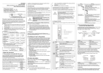
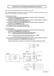
MITSUBISHI
WS0-GCC100202
Safety Controller CC-Link Interface Module
User’s Manual (Hardware)
Mitsubishi Electric Corporation
2-7-3 Marunouchi, Chiyoda-ku, Tokyo, Japan
Mitsubishi Electric Europe BV
Gothaer strasse 8, 40880 Ratingen, Germany
All rights reserved • Specified product properties and technical data do
not represent a guarantee declaration.
MODEL
WS-CC-U-HW
MODEL
13J209
CODE
IB(NA)-0800459-B(1008)MEE
© 2010 MITSUBISHI ELECTRIC CORPORATION
Precautions regarding warranty and specifications
MELSEC-WS series products are jointly developed and manufactured by
Mitsubishi and SICK AG, Industrial Safety Systems, in Germany. Note that
there are some precautions regarding warranty and specifications of
MELSEC-WS series products.
<Warranty>
The gratis warranty term of the product shall be for one (1) year after
the date of delivery or for eighteen (18) months after manufacturing,
whichever is less.
The onerous repair term after discontinuation of production shall be
for four (4) years.
Mitsubishi shall mainly replace the product that needs a repair.
It may take some time to respond to the problem or repair the
product depending on the condition and timing.
<Specifications>
General specifications of the products differ.
MELSEC-Q,
MELSEC-WS
MELSEC-QS
Operating ambient temperature
-25 to 55°C*1
0 to 55°C
Operating ambient humidity
10 to 95%RH
5 to 95%RH
Storage ambient temperature
-25 to 70°C
-40 to 75°C
Storage ambient humidity
10 to 95%RH
5 to 95%RH
*1: When the WS0-GCC100202 is included in the system, operating
ambient temperature will be 0 to 55°C.
EMC standards that are applicable to the products differ.
MELSEC-Q,
MELSEC-WS
MELSEC-QS
EMC standards
EN 61000-6-2, EN 55011
EN 61131-2
1 About this document
1.1 Documentations for the MELSEC-WS system
These manuals apply for the MELSEC-WS CC-Link interface module
WS0-GCC100202 (hereinafter, CC-Link interface module) and only in
combination with the corresponding user’s manual Safety Controller
CC-Link Interface Module User's Manual.
The installation, configuration and commissioning of the MELSEC-WS
safety control system are described in the Safety Controller User’s Manual
and Safety Controller Setting and Monitoring Tool Operating Manual.
Title
Safety Controller User’s Manual
Safety Controller Ethernet Interface User’s
Manual
Safety Controller CC-Link Interface User’s
Manual
Safety Controller Setting and Monitoring
Tool Operating Manual
2 Correct use
4 Product description
CC-Link interface module is a CC-Link based gateway and a part of the
MELSEC-WS system that communicates with primary control systems. It
provides non-safe fieldbus data for control and diagnostic purposes.
Before using the module, check that the following items are provided.
Item
Amount
Remarks
WS0-GCC100202
1
Terminating resistor 110Ω 1/2W
1
Bar terminal
(brown-brown-brown)
Screw terminals (for replacement) (WS0-TBS4) are not available for the
WS0-GCC100202.
The gateway does not have its own power supply and can only be
operated with a MELSEC-WS system.
Up to two gateways can be used in a MELSEC-WS system. These must
be installed directly to the right of the WS0-CPUx.
This gateway must be used only by qualified safety personnel and only on
the machine where it has been installed and initialized by qualified safety
personnel in accordance with the operating manuals.
!
ATTENTION
4.1 Communication data
The CC-Link interface module provides the following data:
input values (ON/OFF) for all MELSEC-WS extension modules and
EFI devices connected
output values (ON/OFF) for all MELSEC-WS input/output extension
modules and EFI devices connected
logic results
the error and status information of all modules
Observe the protective notes and measures in the
MELSEC-WS User’s manual!
Mitsubishi Electric Co. accepts no claims for liability if the equipment is
used in any other way or if modifications are made to the device, even in
the context of mounting and installation.
When mounting, installing and using the MELSEC-WS system,
observe the standards and directives applicable in your country.
These manuals and the related operating manuals must be made
available to the user of the machine where a MELSECWS system is
installed. The machine operator is to be instructed in the use of the
device by qualified safety personnel and must be instructed to read
the operating manuals.
For detailed description of the data set and configuration, please read the
“Safety Controller CC-Link Interface User’s Manual”.
The occurrence of random or systematic faults within the module or in its
control does not impede the MELSEC-WS system’s safety function.
!
ATTENTION
2.1 Disposal
Disposal of unusable or irreparable devices should always occur in
accordance with the applicable country-specific wastedisposal regulations
(e.g. European Waste Code 16 02 14).
Name
Station number
setting switch
Meaning
A switch for configuring a station number for the
module (factory default: 0)
1 to 64: Station number
When the number other than 1 to 64 is
configured, the MS LED flashes in red and the L
RUN/L ERR. LED lights up in red.
Example: Setting the station number 11
Terminal block
DA, DB, DG, SLD
CC-Link dedicated cables are connected for
data link.
For wiring, see Section 4.3.
The SLD terminal is internally connected to the
earthing spring contact. (the connecting part to
the DIN rail).
This two-piece terminal block allows a
replacement of the failed module with the
system being connected to CC-Link network.
(Before replacement, power off the module to be
replaced.)
For the crimp tools, see Chapter 8.
Do not use non-safe data from network modules for
safety related applications.
Network modules only processes non-safety-related
data which is not suitable for operation on a safety
fieldbus.
4.2 Display elements
The CC-Link interface module is equipped with two LEDs: MS and L RUN/
L ERR.
3 Conditions of use for the product
(1) Although MELCO has obtained the certification for Product's
compliance to the international safety standards IEC 61508, EN
954-1/ISO 13849-1 from TUV Rheinland, this fact does not guarantee
that Product will be free from any malfunction or failure. The user of this
Product shall comply with any and all applicable safety standard,
regulation or law and take appropriate safety measures for the system in
which the Product is installed or used and shall take the second or third
safety measures other than the Product. MELCO is not liable for
damages that could have been prevented by compliance with any
applicable safety standard, regulation or law.
(2) MELCO prohibits the use of Products with or in any application
involving, and MELCO shall not be liable for a default, a liability for
defect warranty, a quality assurance, negligence or other tort and a
product liability in these applications.
1) power plants,
2) trains, railway systems, airplanes, airline operations, other
transportation systems,
3) hospitals, medical care, dialysis and life support facilities or
equipment,
4) amusement equipments,
5) incineration and fuel devices,
6) handling of nuclear or hazardous materials or chemicals,
7) mining and drilling,
8) and other applications where the level of risk to human life, health
or property are elevated.
MS LED
Station number setting switch
10
Station number setting switch
1
L RUN/L ERR. LED
4.3 CC-Link dedicated cable connection
The following shows the connection between the CC-Link interface module
and the master station using a CC-Link dedicated cable.
CC-Link
interface module
Master station
Terminal block
SLD
DG
MS
LED
Off
Lights up
Green
Flashes
Green
Flashes
Green/Red
Flashes
Red
Lights up
Red
Number
WS-CPU-U-E
(13JZ32)
WS-ET-U-E
(13JZ33)
WS-CC-U-E
(13JZ45)
SW1DNNWS0ADRB-O-E
(13JU67)
In addition, mounting protective devices also requires specific technical
skills which are not detailed in this documentation.
LED
Meaning
Flashes
One of the following has been detected when
Green/Red data link is active.
• Configuration change of the station number
setting switch
• Terminating register not connected
• Module or CC-Link dedicated cable affected by
noise
L RUN/ Flashes
One of the following has been detected when
L ERR. Red
data link is stopped.
• Configuration change of the station number
setting switch
• Terminating register not connected
• Module or CC-Link dedicated cable affected by
noise
Lights up
Station number setting switch out-of-range
Red
L RUN/
L ERR.
LED
OFF
Lights up
Green
Terminating
register
DA
DB
Meaning
No power supply, immediately after the module
start or hardware failure
Executing (live process data from/to CPU)
Idle (CPU STOP)
DA
DB
DG
SLD
FG
(Blue)
(White)
(Yellow)
CC-Link
dedicated cable
DA
DB
DG
SLD
Terminating
register
Use a bar terminal to connect the cable to the CC-Link interface module.
For applicable bar terminals, see Chapter 8 Cable specifications.
Two poles of each terminal are internally connected. (See below.)
SLD DG DB DA
Executing, but data link stopped or faulty
SLD DG DB DA
Terminating
register
1 Hz: Configuring/configuration required
2 Hz: Critical fault on CC-Link interface module
Critical fault on another module
Meaning
No power supply or data link stopped
Data link active
The above figure shows a view from under the module after wiring.
4.4 Interface
The CC-Link interface module has a removable terminal block for network
connection. The module can be easily replaced without re-wiring. (The
voltage supply to the module must be off before replacing the module.)
5 Mounting/Dismantling
General specifications
1)
!
ATTENTION
The MELSEC-WS system is only suitable for mounting in
a control cabinet with at least IP54 degree of protection.
While supply voltage is applied, gateways must not be
plugged to nor be removed from the MELSEC-WS
system.
To ensure full electromagnetic compatibility (EMC), the
DIN mounting rail must be connected to functional earth
(FE).
2)
5.1 Steps for mounting the modules
In a MELSEC-WS system the CPU module WS0-CPU0 or
WS0-CPU1 is positioned at the extreme left, the two optional
gateways follow directly. Only then do the expansion modules follow.
The relays modules WS0-4RO have to be mounted at the extreme
right.
The modules are located in a 22.5-mm wide modular system for 35
mm DIN rails to EN 60715.
The connection between the modules is effected by means of the
plug connection integrated in the housing.
Mount the module in accordance with EN 50274.
Ensure that suitable ESD protective measures are also taken during
mounting. Otherwise the FLEXBUS+ bus may be damaged.
⇒
Press the module downwards at the rear 1) and remove it from the
DIN rail in the direction of the arrow while keeping it pressed down
2).
6 Configuration and commissioning
!
ATTENTION
Do not commission without a check by specialist
personnel!
Before the initial commissioning of the system in which
you are using a MELSEC-WS system, it must be
checked and released by qualified safety personnel. The
results of this check must be documented.
The CC-Link interface module can be configured using the MELSEC-WS
Setting and monitor tool via the WS0-CPUx module’s RS232 interface.
2)
1)
7 In the event of faults
!
3)
⇒
⇒
⇒
⇒
Make sure that the voltage supply of the MELSEC-WS system is
switched off.
Hang the device onto the DIN rail 1).
Ensure that the earthing spring contact 2) contacts the DIN rail such
that it can electrically conduct.
Latch the module onto the DIN rail by pressing it lightly in the
direction of the arrow 3).
ATTENTION
In the event of unclear faults, cease operation!
Stop the machine if you cannot clearly identify or
allocate the error and if you cannot safely rectify the
malfunction.
Complete functional test after error rectification!
Carry out a full functional test after an error has been
rectified.
8 Technical data
Item
Fieldbus
FLEXBUS+
Ambient operating
temperature
Storage temperature
Humidity
Climatic conditions
Vibration
Rigidity
Protection class
Electromagnetic
compatibility
Housing material
Housing type
Housing enclosure
rating/terminals
Housing color
Weight
Mounting rail
Specifications
24 V DC (16.8 … 30 V DC)
Power consumption
Max. 1.4 W
Item
Ver1.10-compatible
CC-Link dedicated
cable
Cable size
Temperature rating
Material
Core type
Solderless terminal
(bar terminal) and
crimp tool
Interfaces
⇒
⇒
Slide the modules together individually in the direction of the arrow
until the side plug connection latches in.
Install the end clips on the right and left.
5.2 Steps for dismantling the modules
⇒
⇒
Remove the plug-in package terminals with wiring and the end clips.
If there are several modules, slide the modules away from each
other individually in the direction of the arrow until the side plug
connection is separated.
Specifications
CC-Link
Remote device station
Ver.1.10
156kbps/625kbps/2.5Mbps/5Mbps/10Mbps
(autosensing)
1 to 64 (factory default: 0)
1 station (RX/RY 32 points each, RWw/RWr 4
points each)/
2 stations (RX/RY 64 points each, RWw/RWr 8
points each)/
3 stations (RX/RY 96 points each, RWw/RWr
12 points each)/
4 stations (RX/RY 128 points each, RWw/RWr
16 points each)
(The last 16 points of RX/RY are for system
use (reserved).)
CC-Link interface
1 terminal block at the lower part of the module
Cable
Ver.1.10-compatible CC-Link dedicated cable*1
Data interface
Backplane bus (FLEXBUS+)
*1: Connect a terminating resistor (110Ω).
-25°C to +70°C
10% to 95%, non-condensing
According to EN 61131-2
Tested in accordance with IEC 61131-2.
Tested in accordance with IEC 61131-2.
lll
IEC 61000-6-2, EN 55011 Class A
Polycarbonate
Device for control cabinet installation
IP40/IP20 according to IEC 60529
Light grey
120 g
Mounting rail according to IEC/EN 60715
Cable specifications
Supply circuits
Item
Supply voltage
Specifications
CC-Link
10-pin connector for internal safety bus (plug)
0°C to +55°C
Item
Fieldbus
CC-Link station type
CC-Link Version
Data transmission
speed
Station number
Number of occupied
stations
Tightening torque
range
Specifications
For the specifications and any inquiries on the
CC-Link dedicated cables, refer to the
following:
CC-Link Partner Association website:
http://www.cc-link.org/
AWG20
-15°C to +75°C
Conductor: Annealed copper wire (finely
stranded)
Finely stranded
1) Mitsubishi Electric Engineering Co.,Ltd.
• Bar terminal model: FA-TVC125T9
• Crimp tool
: FA-NH65A
2) NICHIFU Co.,Ltd.
• Bar terminal model:
TE0.5-10 (for CC-Link dedicated cable
(0.5mm2)), TE1.5-10 (for SLD)
• Crimp tool: NH-79
3) PHOENIX CONTACT
• Bar terminal model:
AI0.5-10WH (for CC-Link dedicated cable
(0.5mm2)), AI1.5-10BK (for SLD)
• Crimp tool:
CRIMPFOX UD6, CRIMPFOX UD6-4,
CRIMPFOX UD6-6, and CRIMPFOX ZA3
*Note: When a shielded cable is excessively
crimped to a bar terminal using a tool,
CRIMPFOX UD6-4 or CRIMPFOX
UD6-6, the bar terminal may not be
connected to the terminal block
depending on the cross-sectional shape
after crimping.
No torque range specified since two-tier
tension-spring terminal is used.
SICK AG
http://www.sick.com/