1
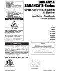
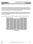
USER'S INFORMATION MANUAL
SERIES 5B
Gas - Fired Boiler
WARNING: If the information in this
manual is not followed exactly, a fire or
explosion may result causing property
damage, personal injury or loss of life.
- Do not store or use gasoline or other
flammable vapors and liquids in the
vicinity of this or any other appliance.
WHAT TO DO IF YOU SMELL GAS
• Do not try to light any appliance.
• Do not touch any electrical switch; do
not use any phone in your building.
• Immediately call your gas supplier
from a neighbor's phone. Follow the
gas supplier's instructions.
• If you cannot reach your gas supplier,
call the fire department.
- Installation and service must be
performed by a qualified installer,
service agency or the gas supplier.
AVERTISSEMENT. Assurez-vous de bien
suivre les instructions données dans cette
notice pour réduire au minimum le risque
d'incendie ou d'explosion ou pour éviter
tout dommage matériel, toute blessure ou
la mort.
- Ne pas entreposer ni utiliser d'essence ni
d'autres vapeurs ou liquides inflam-mables
dans le voisinage de cet appareil ou de tout
autre appareil.
QUE FAIRE SI VOUS SENTEZ UNE ODEUR
DE GAZ:
• Ne pas tenter d'allumer d'appareils.
• Ne touchez à aucun interrupteur. Ne pas
vous servir des téléphones dans le
bâtiment où vous vous trouvez.
• Appelez immédiatement votre
fournisseur de gaz depuis un voisin.
Suivez les instructions du fournisseur.
• Si vous ne pouvez rejoindre le
fournisseur de gaz, appelez le service
des incendies.
- L'installation et I'entretien doivent être
assuréx par un installateur ou un service
d'entretien qualifié ou par le fournisseur de
gaz.
BOILER NOT FOR INSTALLATION ON COMBUSTIBLE
FLOORS UNLESS FLOOR SHIELD OR NATIONAL BUILDING
CODE APPROVED MATERIALS ARE INSTALLED BETWEEN
BOILER AND FLOOR.
Commercial Boilers
www.burnhamcommercial.com
8141303R6 - 8/15
The following terms are used throughout this manual to bring attention to the presence of hazards of various risk levels.
Indicates a potentially hazardous situation which,
if not avoided, could result in death, serious injury
or substantial property damage.
Indicates a potentially hazardous situation which,
if not avoided, may result in moderate or minor
injury or property damage.
Important Product Safety Information
Refractory Ceramic Fiber Product
The Repair Parts list designates parts that contain refractory ceramic fibers
(RCF). RCF has been classified as a possible human carcinogen. When
exposed to temperatures above 1805°F, such as during direct flame contact,
RCF changes into crystalline silica, a known carcinogen. When disturbed as a
result of servicing or repair, these substances become airborne and, if inhaled,
may be hazardous to your health.
AVOID Breathing Fiber Particulates and Dust
Precautionary Measures:
Do not remove or replace RCF parts or attempt any service or repair work
involving RCF without wearing the following protective gear:
1. A National Institute for Occupational Safety and Health (NIOSH)
approved respirator
2. Long sleeved, loose fitting clothing
3. Gloves
4. Eye Protection
•
•
•
•
Take steps to assure adequate ventilation.
Wash all exposed body areas gently with soap and water after contact.
Wash work clothes separately from other laundry and rinse washing
machine after use to avoid contaminating other clothes.
Discard used RCF components by sealing in an airtight plastic bag. RCF
and crystalline silica are not classified as hazardous wastes in the United
States and Canada.
First Aid Procedures:
•
•
•
•
2
If contact with eyes: Flush with water for at least 15 minutes. Seek
immediate medical attention if irritation persists.
If contact with skin: Wash affected area gently with soap and water.
Seek immediate medical attention if irritation persists.
If breathing difficulty develops: Leave the area and move to a location
with clean fresh air. Seek immediate medical attention if breathing
difficulties persist.
Ingestion: Do not induce vomiting. Drink plenty of water. Seek
immediate medical attention.
Basic Operation
Should overheating occur or the gas supply fail to shut off, do not turn off or disconnect the electrical
supply to the pump. Instead, shut off the gas supply at a location external to the appliance.
En cas de surchauffe ou si I'admission de gaz ne peut étre coupée, ne pas couper ni débrancher
l'alimentation électrique de la pompe. Fermer plutôt le robinet d'admission de gaz à l'extérieur de
I'appareil.
Do not use this boiler if any part has been under water. Immediately call a qualified service technician
to inspect the boiler and to replace any part of the control system and any gas control which has been
under water.
A.General This boiler is equipped with controls for
proper operation. All controls must be in proper
working order. Contact a qualified service agency
to provide annual maintenance as specified in the
Installation, Operating and Service Instructions.
Service on this boiler should be undertaken only
by trained and skilled personnel from a qualified
service agency.
B. Instructions to place boiler in operation and to turn
off boiler are shown on the Lighting or Operating
Instruction label posted inside the boiler, behind
the front removable door. See Figure 1 for front
door removal instructions. Lighting and Operating
Instructions are also shown in Figures 2 thru 4.
Lighting and Operating Instructions vary with the type
of control system furnished. Refer to Table 1 for the
appropriate Figure.
Figure 1: Removal of Front & Rear Jacket Panels
Table 1: Lighting and Operating Instructions
IGNITION SYSTEM
MODELS USED ON
OPERATING INSTRUCTIONS
CONTROL LOCATION
DIAGRAM
EI Intermittent Ignition
USA only: 5006B to 5009B
Figure 1
Figure 4
EI Intermittent Ignition
USA: 5010B to 5026B
Canada: All
Figure 2
Figure 5
EP Intermittent Ignition
USA and Canada: All
Figure 3
Figure 6
3
FOR YOUR SAFETY READ BEFORE OPERATING
WARNING: If you do not follow these instructions exactly, a fire or explosion may result
causing property damage, personal injury, or loss of life.
A. This appliance is equipped with an ignition device
which automatically lights the pilot. Do not try to light
the pilot by hand.
B. BEFORE OPERATING smell all around the appliance area
for gas. Be sure to smell next to the floor because some
gas is heavier than air and will settle on the floor.
WHAT TO DO IF YOU SMELL GAS:
Do not try to light any appliance.
Do not touch any electric switch; do not use any
phone in your building.
Immediately call your gas supplier from a neighbor's
phone. Follow the gas supplier's instructions.
If you cannot reach your gas supplier, call the
fire department.
C. Use only your hand to turn the gas control knob.
Never use tools. If the knob will not turn by hand,
don't try to repair it, call a qualified service technician.
Force or attempted repair may result in a fire or
explosion.
D. Do not use this appliance if any part has been under
water. Immediately call a qualified service technician
to inspect the appliance and to replace any part of the
control system and any gas control which has been
under water.
OPERATING INSTRUCTIONS
1. STOP! Read the safety information above on this label.
2. Set the thermostat or operating control to lowest setting.
3. Turn off all electric power to the appliance.
4. This appliance is equipped with an ignition device
which automatically lights the pilot. Do not try to
light the pilot by hand.
POSITION
INDICATOR
5. Locate the gas control
valve at the end of the gas
supply pipe going into the
boiler. The gas control
GAS
knob is the gray or brown INLET
plastic knob located on top
of the gas control valve.
ON
OFF
6. Rotate gas control knob clockwise
from "ON"
position to "OFF". Make sure knob rests against stop.
7. Wait five (5) minutes to clear out any gas. Then smell
for gas, including near the floor. If you smell gas,
STOP! Follow "B" in the safety information above on
this label. If you do not smell gas, go to the next step.
8. Rotate gas control knob counterclockwise
from
"OFF" to "ON". Make sure knob rests against stop. Do
not force.
9. Turn on all electric power to the appliance.
10. Set thermostat or operating control to desired setting.
GAS CONTROL KNOB
SHOWN IN "OFF" POSITION
11. If the appliance will not operate, follow the
instructions "TO TURN OFF GAS TO APPLIANCE"
and call your service technician or gas supplier.
TO TURN OFF GAS TO APPLIANCE
1. Set the thermostat or operating control to the lowest setting.
2. Turn off all electric power to the appliance if service is
to be performed.
3. Rotate gas control knob clockwise
from "ON"
position to "OFF". Make sure knob rests against stop.
81460028R6
Figure 2: Lighting Instructions, EI Intermittent Ignition System
USA Only: 5006B thru 5009B
4
FOR YOUR SAFETY READ BEFORE OPERATING
WARNING: If you do not follow these instructions exactly, a fire or explosion may result
causing property damage, personal injury, or loss of life.
A. This appliance is equipped with an ignition device
which automatically lights the pilot. Do not try to light
the pilot by hand.
B. Do not use this appliance if any part has been under
water. Immediately call a qualified service technician
to inspect the appliance and to replace any part of the
control system and any gas control which has been
under water.
C. BEFORE OPERATING smell all around the appliance area
for gas. Be sure to smell next to the floor because some
gas is heavier than air and will settle on the floor.
WHAT TO DO IF YOU SMELL GAS:
Do not try to light any appliance.
Do not touch any electric switch; do not use any
phone in your building.
Immediately call your gas supplier from a neighbor's
phone. Follow the gas supplier's instructions.
If you cannot reach your gas supplier, call the
fire department.
OPERATING INSTRUCTIONS
1. STOP! Read the safety information above on this label.
2. Set the thermostat or operating control to lowest setting.
3. Turn off all electric power to the appliance.
4. This appliance is equipped with an ignition device
which automatically lights the pilot. Do not try to
light the pilot by hand.
5. Make sure the manual main shut-off valve(s) and pilot
valve(s) have been shut off for at least five minutes.
shut-off for at least five minutes.
Then smell for gas, including near the floor.
If you smell gas, STOP! Follow "B" in the safety
information above on this label.
If you do not smell gas, go to the next step.
6. Turn manual main shut-off valve(s) and pilot valve(s)
to "ON" position.
7. Turn on main electric switch.
8. Set thermostat or operating control to desired setting.
Make sure that all limit controls have been set for
normal system operating requirements.
Pilot will automatically ignite main burners on each call
for heat.
TO TURN OFF GAS TO APPLIANCE
1. Set the thermostat or operating control to the lowest setting.
2. Close manual main shut-off valve(s) and pilot valve(s).
3. Turn off all electric power to the appliance if service is
to be performed.
81460073R3
Figure 3: Operating Instructions, EI Intermittent Ignition System
USA Only: 5010B thru 5026B
Canada: All
5
FOR YOUR SAFETY READ BEFORE OPERATING
WARNING: If you do not follow these instructions exactly, a fire or explosion may result
causing property damage, personal injury, or loss of life.
A. This appliance is equipped with an ignition device
which automatically lights the pilot. Do not try to light
the pilot by hand.
B. Do not use this appliance if any part has been under
water. Immediately call a qualified service technician
to inspect the appliance and to replace any part of the
control system and any gas control which has been
under water.
C. BEFORE OPERATING smell all around the appliance
area for gas. Be sure to smell next to the floor because
some gas is heavier than air and will settle on the floor.
WHAT TO DO IF YOU SMELL GAS:
Do not try to light any appliance.
Do not touch any electric switch; do not use any
phone in your building.
Immediately call your gas supplier from a neighbor's
phone. Follow the gas supplier's instructions.
If you cannot reach your gas supplier, call the
fire department.
OPERATING INSTRUCTIONS
1. STOP! Read the safety information above on this label.
2. Set the thermostat or operating control to the lowest setting.
3. Turn off all electric power to the appliance.
6. Make sure the manual main shut-off valve(s) and pilot
valve(s) have been shut off for at least five minutes.
Then smell for gas, including near the floor.
4. EP SYSTEM: Flip both rocker switches to "O" position (off).
7. Open the manual pilot valve(s)
5. This appliance is equipped with an ignition device
which automatically lights the pilot. Do not try to light
the pilot by hand.
8. Turn on all electric power to the appliance.
RESET SAFETY
SWITCH BUTTON
RM7890
ELECTRONIC
CONTROL
PANEL
MAIN POWER
ROCKER
SWITCH
MAIN GAS ROCKER
SWITCH
CONTROL LOCATION DIAGRAM
9. Set the thermostat or operating control to desired
setting.
10. EP SYSTEM
See control location diagram. On the electronic control
panel, flip the main power rocker switch to "l" position
(on). The "POWER" status indicator will light.
The pilot will light electronically. If pilot failure occurs,
the "ALARM" indicator will light. In case of pilot
failure, proceed to step 11.
Open manual main shut-off valve(s).
On the electronic control panel, flip the main gas valve
rocker switch to "l" position (on). The "MAIN" gas valve
indicator will light. Main burners will operate.
"MAIN" gas valve indicator will cycle on and off at the
same time as the thermostat or operating control and
the main burners.
11. If the appliance will not operate, follow the instructions
"TO TURN OFF GAS TO APPLIANCE" and call your
service technician or gas supplier.
TO TURN OFF GAS TO APPLIANCE
1. Set the thermostat and all operating controls to the
lowest setting.
3. Turn off all electric power to the appliance if service is
to be performed.
2. Close manual main shut-off valve(s) and pilot valve(s).
Figure 4: Operating Instructions, EP Ignition System
6
81460048R3
Figure 5: EI Control Locations
(USA Only: 5006 thru 5009)
Figure 6: EI Control Locations
(USA Only: 5010 thru 50026)
Canada: All
Figure 7: EP Control Locations
7
User Maintenance
Service on this boiler should be undertaken only by trained and skilled personnel from a qualified service
agency. Inspections should be performed at intervals specified in Installation, Operating and Service
Instructions and this manual. Maintain manuals in a legible condition.
Keep boiler area clear and free of combustible materials, gasoline and other flammable vapors and liquids.
Do not place any obstructions in boiler room that will hinder flow of combustion and ventilation air.
A. General Housekeeping (Continuous).
1. Keep boiler area clear and free of combustible
materials and obstructions to the free flow of
combustion and ventilation air to the boiler.
2. Do not store or use gasoline or other flammable
vapors or liquids in the vicinity of the boiler or any
other appliance.
3. Do not store or use sources of hydrocarbons in
the vicinity of the boiler. Sources of hydrocarbons
include bleaches, cleaners, chemicals, sprays, paint
removers, fabric softeners, cat litter and refrigerants.
B. Inspect Vent System (Monthly). See Figure 8. Follow
instructions TO TURN OFF GAS TO APPLIANCE
(see Figures 2 thru 4) and contact a qualified service
agency if any of the following conditions are found:
1. Collapsed vent pipe
2. Disconnected or loose joints
3. Sags in horizontal runs
4. Corrosion or other deterioration
5. Broken or loose supports
C. Examination of Pilot and Main Burner Flames.
8
Pilot flame(s) and main burner flame should be checked
annually, after each flueway cleaning, or after an
extended shutdown period. Six through 14 section
boilers are equipped with one (1) pilot, whereas larger
than 14 section boilers are equipped with two (2) pilots.
To observe the pilot flame(s) and main burner flame,
remove the Lower Front Jacket Panel(s) by grasping
the knobs on the panel, and while pushing up on the
panel, pull out on the bottom of the panel. Immediately
behind the Lower Jacket Front Panel are a number of
observation port covers. Select a cover that is directly
behind a pilot, loosen the screw at the top of the cover
and with a pair of pliers (cover may be hot) rotate cover
until observation port is uncovered. Retighten screw to
hold cover in this position.
1. Pilot Flame
All of the pilots used on the Series 5B boilers have
tips that produce three flames, one left, one right
and one straight ahead. The center or straight
ahead flame should be a blue medium hard flame
enveloping approximately 3/8" of the end of the
sensing probe mounted on the pilot burner, see
Figure 9. If the flame is yellow and lazy, a qualified
service agency should be called.
2. Main Flame
Main burner flame should have a clearly defined
inner cone, see Figure 10, with no yellow tipping.
Orange-yellow streaks caused by dust should not be
confused with true yellow tipping. If yellow flames
are observed, a qualified service agency should be
called.
After flame observations have been completed,
relocate port cover so the observation hole is closed,
then secure cover in this position. Reinstall Lower
Jacket Front Panel.
Figure 8: Recommended Vent Systems
Figure 10: Typical Main Burner Flame
Figure 9: Typical Pilot Flame
9
D. Examination of Flue Product Carrying Areas.
1. Boiler
Flue passageways in the boiler sections should be
checked annually for any blockage or accumulation
of soot. A think layer of soot on the flue gas
passageways will affect heat transfer substantially.
The resultant loss in efficiency will have a direct
bearing on increased fuel consumption.
Blockage of the flues is hazardous. If severe, carbon
monoxide concentrations could be lethal during the
burning cycle. Flames could roll outside the jacket
creating a fire hazard. The heat concentration could
severely damage the base, warp the burners, melt
the pilot tubing and wire insulation and destroy the
ignition module inside the jacket vestibule.
To obtain access to the flue cleanout panels, which
are installed on both the front and rear of the boiler,
the upper front and upper rear jacket panels must be
removed.
If access to the flue cleanout panels facing the front
of the boiler is required, the front vestibule panel
must be removed. See Figure 11.
Remove the Front Cleanout Panels first by removing
the upper and lower nuts and washers securing these
panels to the boiler sections, see Figure 11.
CARE SHOULD BE EXERCISED IN
REMOVING THE CLEANOUT PLATES FROM
THE BOLTS SO THAT THE INSULATION IS
NOT DAMAGED. IF DAMAGED, ALL EDGES
OF THE CLEANOUT PLATES SHOULD BE
SEALED WITH BOILER PUTTY WHEN
REINSTALLED UNTIL INSULATION CAN BE
REPLACED.
Using a flashlight, examine all flue passageways. If
passageways are free of soot and obstruction, it is
not necessary to remove the rear cleanout panels.
If the flues need cleaning or are obstructed, call a
qualified service agency.
Figure 11: Inspection of Boiler Flueways
10
11
All Series 5B repair parts may be obtained through your local Burnham Wholesale distributor. Should you
require assistance in locating a Burnham distributor in your area, or have questions regarding the availability
of Burnham products or repair parts, please contact Burnham Customer Service at
888-791-3790 or Fax (717) 293-5803.
12