Transcript
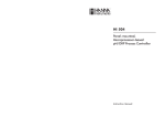
DK-5000 SERIES MANUAL
TYPE
INSTRUCTION MANUAL
B
DK-5010B
ATTENTION!
● Customer Service
LINE SEIKI CO., LTD.
Thank you for purchasing our product, DK-5010B.
Please confirm that you have the correct device by checking the product label.
Please read this instruction manual carefully before using this device to ensure correct usage.
Please keep this instruction manual for future reference.
■ INTRODUCTION
Please note that misuse of this device may lead to injury
to the user or damage to the device.
Please observe all safety precautions and warnings in
this instruction manual.
Head Office 37-7 Chuo-cho, 2-Chome Meguro-ku,
Tokyo JAPAN 152-0001
Contact
TEL:03-3716-5151 FAX:03-3710-4552
E-mail
[email protected]
URL
http://www.lineseiki.com
※ Important!
This device requires DK-5000 Mieruzzo Software to view record details. The software runs
on Windows 7, 8 or 8.1 OS.
Please use a micro B-to-A USB cable to connect the DK-5010B device to a computer.
The companion software enables user to download, delete and save data from the device to a
computer. The software also enables real-time display of the device on a computer.
■ POWER SUPPLY
※ Please use Line Seiki AC/DC Power Adapter for DK-5000 (sold separately) to power the device
via DC jack.
Upon initial connection to a power supply or resumption of power, the device will perform the
start-up routine, blinking all LCD segments for 2 ‒ 7 seconds. After the start-up routine, the device
will proceed to Date & Time Setting Mode to set the device Date & Time.
(See KEY OPERATION for details.)
※ Important!
download the data from the device
export the downloaded data to a .XLS or .CSV file
delete records stored in the device
sync device time to computer system time
change Device ID
Please refer to the DK-5000 Mieruzzo Software User Manual for more details.
When the device is connected to the software, the
of its display.
①②
TIMEM ROW
88:88
⑯
⑮
8
888888
⑭
F
SUB
③
Setting Mode
Standby Mode
TIME
Logging of input key press is enabled in this mode. The number of inputs for each input key and
the total inputs are updated with every press of corresponding input key.
YYYY
MM
DD
hh
By pressing the corresponding key combination of [F] with [1], [2] or [3], other operation modes
can be accessed from Recording Mode. By holding down [#], Standby Mode can be enabled.
(See KEY OPERATION for details.)
Setting Mode
⑧
⑨
POWER
1
2
3
4
① Clock / Memory No. Display
② Row Display
③ Input Display
④ Date/Time Icon
⑤ Subtract Icon
⑥ Low Battery Icon
⑦ Software Link Icon
⑧ 5.5 mm DC Jack
Memory Recall Mode
This mode enables viewing of all saved Records on the device memory. Memory Recall Mode is
indicated by MEM icon and the 4-digit Memory No. shown on the upper left side of the display.
MEM
01
DD
08
hh
15
mm
Memory No. represents the memory location of the Record displayed. When a Record is deleted,
the memory location of each Record shifts and Memory No. is changed accordingly.
F
+
2
10
Note:
* While [SUB] is held down, the "SUB" icon will appear on the upper
right corner of the display.
● ROW KEY
Recording Mode, Memory Recall Mode
■ MEMORY CAPACITY
The device memory can save up to 250 records, which is achieved when only a maximum of 111
Timestamps are saved per record.
MEM
A memory low indicator
used is 80% or more.
YES
nO
CLr
Start/End Record
♦ While in Standby Mode, hold down [#] for 1 second to start recording of
data. A Record will be created with corresponding Start Timestamp. The
device will enter Recording Mode and logging is enabled. The display will
show "0" number of inputs.
1.) The Record will be a collection of data logs composed of input
Timestamps, which will be saved on every press of input keys.
♦ While in Recording Mode, hold down [#] for 1 second again to end
recording of data. The Record will be terminated and saved with
corresponding number of inputs and End Timestamp.
2.) The Memory No., indicated by MEM, will increment by 1
everytime a new Record is saved.
3.) While saving, the display will blink twice showing the Memory
No. and corresponding Timestamp, then the values saved.
#
MEM
YYYY
MM
30
23
DD
♦ Hold down [F] and press [2] to enter the Device ID Setting Mode. The
display will show the Device ID, a 3-digit user-programmable number
which is used to identify different DK-5000 devices.
0
0
0
DD
08
hh
30
mm
1245 5689 8910 2468 1012
TIME
stnd by
08:30
A memory full indicator
※ Important!
lO
will be blinking twice every 5 seconds when the size of memory
MEM
fUll will be blinking when 100% of memory is used.
When memory is full, starting a new Record will erase the oldest Record to free up memory
space for the new Record created. Location of Records will shift and Memory No. will change
accordingly.
When memory is full and device is in Recording Mode, saving a new log that requires
additional memory space will erase the oldest Record to free up memory space. While
erasing a Record, the device will show a "Record Data to Clear" message, and logging of
input key press is temporarily disabled.
■ SPECIFICATIONS
Count Range
Display: 4-Digit 0
9999, Internal: 5-Digit 0 99999
Total Count Range
6-Digit 0 999999
Operating Temperature
0°
C
Operating Humidity
35 85% RH (non-condensing)
Storage Temperature
-10°
C
Dimension
96 (H) x 170 (W) x 25 (D) mm
Weight
Approx. 185g (accessories not included)
Compliance
CE, RoHS
50°
C (non-freezing)
60°
C (non-freezing)
For more details, please visit our website at http://www.lineseiki.com
ATTENTION!
Operation
- Do not use this device near machines that emit strong electromagnetic fields or objects
that store static electricity.
- Do not drop or subject this device to strong impact.
- Do not use or store this device where it will be exposed to water or in places with
wet conditions.
- Do not use or store this device where it can be exposed to high temperature and high
humidity.
- See the battery case markings to ensure that the batteries are properly installed.
- Do not attempt to disassemble or modify this device.
- When using the device via USB power, avoid excessive movement to ensure that the
device will not be disconnected and power will not be lost.
- The unit is shipped with protective seal on the display.
Note :
* The Record End Timestamp will be used to identify Records in
Memory Recall Mode and as Record Name when data is
downloaded on the companion software.
● INPUT KEYS
Recording Mode
1
Device ID Setting
01
4.) After saving, the device will enter Standby Mode and data
recording is disabled.
mm
The Year, Month, Day, Hour or Minute values can be incremented by
pressing [1], [2], [3], [4] or [5]. Holding down [1], [2], [3], [4], or [5] will
continuously increment these values, respectively.
♦ Press [F] to leave the Date & Time Setting Mode.
1 d
2
59
hh
MM
ROW
19324
2014 11
YYYY
2014 12
0002
0002
Note :
* Editing of Date & Time is disabled when accessed from
Recording Mode.
When accessed from Standby Mode, Date & Time, and Device ID can be viewed and edited,
respectively. When accessed from Recording Mode, editing is disabled.
(See KEY OPERATION for details.)
♦ Holding down [SUB] and also holding down these keys will continuously
decrement the values being edited.
♦ While in Recording Mode or Input Value Display in Memory Recall Mode,
press [ROW] to change the row displayed between Row 1 and Row 2.
Row 1 will show Input 1 ‒ Input 5
Row 2 will show Input 6 ‒ Input 10.
● [#] KEY
♦ Hold down [F] and press [1] to enter the Date & Time Setting Mode. The
display will show the Date and Time value in the format below:
"YYYY-MM-DD-hh-mm".
a.) Date & Time Setting
b.) Device ID Setting
MM
⑨ Power Key
⑩ [#] Key
⑪ Row Key
⑫ Input Keys
⑬ Subtract Key
⑭ Function Key
⑮ USB 2.0 Port
⑯ Total Input Display
Date & Time Setting
1
There are two Setting Modes:
mm
Note:
* Memory All Clear Mode is disabled when Recording Mode is
active.
* Make sure to keep the device powered while clearing memory
or deleting Records to avoid risk of data corruption.
⑩
#
5
● [F] KEY
+
15
♦ Press [5] to select "No". No Record will be deleted and the device will
return to Memory Recall Mode.
♦ Press [F] to leave Memory All Clear Mode.
mm
DK-5000 Series
MEM
F
hh
All dAtA ____ ____
When switching off from Recording Mode, the Record will be ended and
saved before switching off.
1245 5689 8910 2468 1012
08
♦ Hold down [4] for 1 second to select "Yes". All Records will be deleted
and device will return to Memory Recall Mode, "no data" will be displayed.
While clearing the memory, device will show "All Data to Clear".
♦ To switch ON, hold down [POWER] for 1 second.
The default power up display is Standby Mode showing the text "Standby"
on the display.
♦ To switch OFF, hold down [POWER] for 3 seconds.
ROW
YYYY
ALL CLr
Power (On/Off)
Recording Mode is indicated by the displayed number of inputs for each input key and the total
inputs. The
icon and the current time is also shown on the upper left side of the display.
2014 10
3
● POWER KEY
Recording Mode
DD
♦ When in Memory All Clear Mode, the display will show the "All Clear"
options.
■ KEY OPERATION
By pressing the corresponding key combination of [F] with [1], [2] or [3], other operation modes
can be accessed from Standby Mode. By holding down [#], Recording Mode can be enabled.
(See KEY OPERATION for details.)
to
SUB
⑬⑫
Logging of input key press is disabled in this mode.
0001
+
⑪
stnd by
08:15
01
Memory All Clear
8888 8888 8888 8888 8888
Memory Recall Mode
This is the default operation mode. Standby Mode is indicated by the displayed text "Standby".
The
icon and the current time is also shown on the upper left side of the display.
MM
♦ Press [1] to display the next Record.
♦ Press [2] to display the previous Record.
♦ Press [3] to toggle Timestamp Display mode.
♦ Press [4] to toggle Input Value Display mode.
♦ Press [5] to enter Memory All Clear Mode.
♦ Press [F] to leave the Memory Recall Mode.
⑤
⑥
⑦
④
♦ Hold down [SUB] and press [1], [2], [3], [4] or [5] to decrement values
being edited such as Year, Month, Day, Hour, Minute, or Device ID digit
values.
1
nO dAtA
icon will appear on the upper right corner
■ LABELS
Setting Mode
+
If there is no Record available, the display will show "no data".
F
The software also has an Auto Acquire function which enables real-time display of the number of
inputs displayed on the device. The display is updated every 1 second.
This device has four main operation modes, namely:
Recording Mode
2014 10
YYYY
This device works with DK-5000 Mieruzzo Software. The software is downloadable for free from
the Line Seiki website.
•
•
•
•
•
♦ Hold down [SUB] and press any of the input keys to decrement the
number of inputs.
SUB
MEM
0001
■ OPERATION MODES
•
Memory Recall
■ SOFTWARE
If all power supplies are removed, the last device Date & Time will be stored in a temporary
memory. If device is in Recording Mode, Record will be saved. When the device is powered ON
again, it will resume operation in Date & Time Setting Mode using the last saved Date & Time
values.
(See KEY OPERATION for details.)
•
2
♦ Hold down [F] and press [3] to enter Memory Recall Mode. The display
will show the Memory No. and Timestamp of the newest Record saved.
► when battery is almost empty
► when no battery is installed while the device is powered by DC jack and/or USB
19324
Note :
* Editing of Device ID is disabled when accessed from Recording
Mode or when there is an active connection to the companion
software.
Memory Recall Mode also provides an option to clear all Records saved in the device memory.
(See KEY OPERATION for details.)
icon will appear on the upper right corner of the display to indicate a low battery condition.
icon will blink continuously under following conditions:
08:15 2
♦ Press [F] to leave the Device ID Setting Mode.
Input Value Display mode will show the number of individual inputs and the total inputs.
When operating only on batteries, fresh Alkaline type batteries can provide at least up to 200
hours of operation, under normal operating condition.
TIME
+
Timestamp Display mode will show the date and time when the Record is saved.
Calendar clock will not update when there is no power supply available. Make sure that
there are batteries installed before disconnecting both DC jack and USB power supply to
maintain calendar clock function. When DC jack or USB power is connected, power is not
supplied from the batteries and battery charge will not be drained.
•
Each digit of the Device ID can be incremented by pressing [3], [4] or [5].
Holding down [3], [4] or [5] will continuously increment each digit.
The software enables the user with the following functions:
► 5.5mm DC Jack @9V, 50mA ※
► USB Power @5V, 100mA
► 4pcs. AAA Battery
•
F
a.) Timestamp Display
b.) Input Value Display
The device can be powered through three power supply options. The list below shows the power
supply options according to priority of usage:
Recording Mode
Device ID Setting (continuation)
There are two display modes available for viewing stored Records:
DK-5010B is an input device which logs timestamp of ten (10) input keys. It can save records in its
memory and has a built-in calendar clock for timestamp. Its ten input keys can be used to monitor
different types of event, attribute or classification.
Standby Mode
● [SUB] KEY
● [F] KEY
to
10
♦ While in Recording Mode, press any of the input keys to enter an input
Timestamp and increment the number of inputs.
TIME
ROW
08:15 2
19324
1245 5689 8910 2468 1012
Note:
* Make sure to push the input keys properly to avoid missed input.
This manual was last revised June 15, 2015. 4DK5005A
Contents are subject to change even without prior notice.
All Rights Reserved, Copyright © 2015, LINE SEIKI CO., LTD.