1
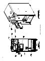
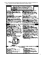
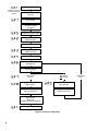
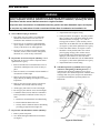
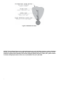
USER'S INFORMATION MANUAL
ESC™
Gas - Fired Boiler
WARNING: If the information in this
manual is not followed exactly, a fire or
explosion may result causing property
damage, personal injury or loss of life.
- Do not store or use gasoline or other
flammable vapors and liquids in the
vicinity of this or any other appliance.
- WHAT TO DO IF YOU SMELL GAS
• Do not try to light any appliance.
• Do not touch any electrical switch; do
not use any phone in your building.
• Immediately call your gas supplier
from a neighbor's phone. Follow the
gas supplier's instructions.
• If you cannot reach your gas supplier,
call the fire department.
- Installation and service must be
performed by a qualified installer,
service agency or the gas supplier.
103790-02 - 9/13
AVERTISSEMENT. Assurez-vous de bien
suivre les instructions données dans
cette notice pour réduire au minimum
le risque d'incendie ou d'explosion ou
pour éviter tout dommage matériel, toute
blessure ou la mort.
- Ne pas entreposer ni utiliser d'essence
ni d'autres vapeurs ou liquides
inflammables dans le voisinage de cet
appareil ou de tout autre appareil.
- QUE FAIRE SI VOUS SENTEZ UNE
ODEUR DE GAZ:
• Ne pas tenter d'allumer d'appareils.
• Ne touchez à aucun interrupteur. Ne
pas vous servir des téléphones dans
le bâtiment où vous vous trouvez.
• Appelez immédiatement votre
fournisseur de gaz depuis un voisin.
Suivez les instructions du
fournisseur.
• Si vous ne pouvez rejoindre le
fournisseur de gaz, appelez le
service des incendies.
- L'installation et I'entretien doivent
être assurés par un installateur ou un
service d'entretien qualifié ou par le
fournisseur de gaz.
The following terms are used throughout this manual to bring attention to the presence of hazards of various risk levels.
WARNING
CAUTION
Indicates a potentially hazardous situation which,
if not avoided, could result in death, serious injury
or substantial property damage.
Indicates a potentially hazardous situation which,
if not avoided, may result in moderate or minor
injury or property damage.
Important Product Safety Information
Refractory Ceramic Fiber Product
Warning:
The Repair Parts list designates parts that contain refractory ceramic fibers
(RCF). RCF has been classified as a possible human carcinogen. When
exposed to temperatures about 1805°F, such as during direct flame contact,
RCF changes into crystalline silica, a known carcinogen. When disturbed as a
result of servicing or repair, these substances become airborne and, if inhaled,
may be hazardous to your health.
AVOID Breathing Fiber Particulates and Dust
Precautionary Measures:
Do not remove or replace RCF parts or attempt any service or repair work
involving RCF without wearing the following protective gear:
1. A National Institute for Occupational Safety and Health (NIOSH)
approved respirator
2. Long sleeved, loose fitting clothing
3. Gloves
4. Eye Protection
•
•
•
•
Take steps to assure adequate ventilation.
Wash all exposed body areas gently with soap and water after contact.
Wash work clothes separately from other laundry and rinse washing
machine after use to avoid contaminating other clothes.
Discard used RCF components by sealing in an airtight plastic bag. RCF
and crystalline silica are not classified as hazardous wastes in the United
States and Canada.
First Aid Procedures:
•
•
•
•
2
If contact with eyes: Flush with water for at least 15 minutes. Seek
immediate medical attention if irritation persists.
If contact with skin: Wash affected area gently with soap and water.
Seek immediate medical attention if irritation persists.
If breathing difficulty develops: Leave the area and move to a location
with clean fresh air. Seek immediate medical attention if breathing
difficulties persist.
Ingestion: Do not induce vomiting. Drink plenty of water. Seek
immediate medical attention.
Basic Operation
CAUTION
Should overheating occur or the gas supply fail to shut off, do not turn off or disconnect the electrical
supply to the pump. Instead, shut off the gas supply at a location external to the appliance.
En cas de surchauffe ou si I'admission de gaz ne peut étre coupée, ne pas couper ni débrancher
l'alimentation électrique de la pompe. Fermer plutôt le robinet d'admission de gaz à l'extérieur de I'appareil.
Do not use this boiler if any part has been under water. Immediately call a qualified service technician to
inspect the boiler and to replace any part of the control system and any gas control which has been under
water.
A.General. This water boiler utilizes fan-assisted
combustion and is equipped with controls for proper
operation. All controls must be in proper working order.
Contact a qualified service agency to provide annual
maintenance as specified in Installation, Operating and
Service Instructions.
1.Limit. See Figure 1. A device which automatically
interrupts boiler operation when the water
temperature exceeds the set point. Maximum
allowable temperature is 220°F.
Original equipment with this boiler is U.S. Boiler
IQ Control and Limit Rated Sensor combination.
The IQ Control shuts off boiler main burners when
boiler water temperature exceeds pre-programmed
IQ control water temperature set point. Boiler main
burners will re-light automatically, providing the call
for heat is present, when boiler water temperature
falls below pre-programmed control water
temperature set point less the set point differential.
2. Flame Rollout Switch. See Figure 1. A device
which automatically interrupts boiler operation
when flames or excessive heat are present in the
combustion area enclosure. The control is a single
use device. The control is located in the combustion
area enclosure. If the control was activated to
interrupt boiler operation, do not attempt to place
boiler in operation. Contact a qualified service
agency.
WARNING
Service on this boiler should be undertaken only
by trained and skilled personnel from a qualified
service agency.
3. Pressure Switch. See Figure 1. A device which
automatically prevents or interrupts boiler
operation when the induced draft blower fails to
move sufficient combustion air for proper burner
operation. Boiler operation resumes automatically
when sufficient combustion air flow is reestablished.
4. Electronic Ignition System. The Electronic Ignition
(EI) System consists of:
a. a solid state ignition control module to initiate,
monitor and stop burner operation. See Figure 1.
b. a combination gas valve to regulate gas flow to
the burners. See Figure 1.
c. a pilot burner to provide the ignition source for
the main burners. See Figure 4.
B.Instructions to place the boiler in operation and to turn
off the boiler are shown on the Operating Instruction
Label posted on the left jacket panel of the boiler. The
Operating Instruction Label is shown in Figure 2.
C. The Sequence of Operation is shown in Figure 3.
3
4
Figure 1: Control Locations
NOTE: YOUR BOILER IS EQUIPPED WITH A HONEYWELL VR8204 OR VR8304 GAS
VALVE. PLEASE FOLLOW THESE OPERATING INSTRUCTIONS:
Figure 2: Operating Instructions
5
Standby
Intelligent Hydronic
Control can display
(typical)
Thermostat Calls
for Heat
Self Testing
Circulator Output
Energized
Waiting for Limit to Close
Waiting for Pressure
Switch to Open
Blower Starts
Waiting for Pressure
Switch to Close
Prepurge (30 seconds)
Ignition Source Energized
Pilot Gas On
Trial For Ignition
Pilot Flame
Proven
Pilot Flame
Not Proven
Ignition Source Off
Main Gas On
Ignition Source Off
Pilot Gas Off
Call For Heat Ends
Delay 60 Seconds
Main Gas Off
Blower Off
Circulator Output De-Energized
Standby
Figure 3: Sequence of Operation
6
Continuous
Retry
User Maintenance
WARNING
Service on this boiler should be undertaken only by trained and skilled personnel from a qualified service
agency. Inspections should be performed at intervals specified in Installation, Operating and Service
Instructions and this manual. Maintain manuals in a legible condition.
Keep boiler area clear and free of combustible materials, gasoline and other flammable vapors and liquids.
Do not place any obstructions in boiler room that will hinder flow of combustion and ventilation air.
A. General Housekeeping (Continuous).
1. Keep boiler area clear and free of combustible
materials and obstructions to the free flow of
combustion and ventilation air to the boiler.
2. Do not store or use gasoline or other flammable
vapors, liquids or sources of hydrocarbons in the
vicinity of the boiler or any other appliance.
3. Do not store or use halogen-containing products
(bleaches, cleaners, fabric softeners, refrigerants,
chemicals, etc.) in the vicinity of the boiler.
B. Inspect Inlet Air and Vent System (Monthly). Check
the following. If corrective action is required contact
qualified service agency.
1. Inlet air terminal and vent terminal must be free of
obstruction, undamaged, with screens securely in
place.
2. Inlet air terminal, vent terminal, and wall thimble (if
used) must be weather-tight.
3. Inlet air pipe and vent pipe must be full round
shape, showing no damage from impact or excessive
temperature.
3. Adjust thermostat to highest setting.
4. Check pilot flame. See Figure 4. The pilot produces
three (3) flames. The center flame should be steady,
medium hard blue enveloping 3/8 to ½ inch of
sensing probe. If flame is yellow and lazy, follow
instructions TO TURN OFF GAS TO APPLIANCE
(see Figure 2), and contact qualified service agency.
5. Check main burner flames. See Figure 5. Flame
should have clearly defined inner cone with no
yellow tipping. Orange-yellow streaks caused
by dust should not be confused with true yellow
tipping. If yellow flames are observed, follow
instructions TO TURN OFF GAS TO APPLIANCE
(see Figure 2), and contact qualified service agency.
6. Adjust thermostat to normal setting.
D. Schedule Inspection by Qualified Service Agency
(Annual or at Beginning of Heating Season). For
continued safe operation a qualified service agency
must provide a more detailed inspection of burners, heat
exchanger and vent system, and provide maintenance
as specified in Installation, Operating and Service
Instructions.
4. Inlet air pipe and vent pipe must be supported at
minimum 5 foot intervals and must not sag.
5. All inlet pipe joints must be secure and airtight.
6. All vent pipe joints must be secure and watertight.
7. Condensate drain (if used) must have minimum 6
inch trap and allow condensate to flow freely. To
clean:
a. Disconnect condensate drain from drain fitting.
b. Flush condensate drain with water.
c. Securely fasten condensate drain to drain fitting,
providing gas-tight and water-tight seal.
C. Inspect Pilot and Main Burner Flames (Monthly).
1. Remove jacket front panel.
2. View flames through combustion area enclosure.
See Figure 1.
Figure 4: Pilot Burner
7
Figure 5: Main Burner Flame
All ESC™ Series Repair Parts may be obtained through your local U.S. Boiler Company product distributor.
Should you require assistance in locating a U.S. Boiler Company product distributor in your area, or have
questions regarding the availability of U.S. Boiler Company brand products or repair parts, please contact
U.S. Boiler Company Customer Service at (717) 481-8400 or Fax (717) 481-8408.
8